


Instruction Manual |
DLC3010 Digital Level Controller |
D102748X012 |
October 2014 |
|
|
Fisherr FIELDVUE™ DLC3010 Digital Level
Controller
This manual applies to:
Device Type |
3010 |
Device Revision |
1 |
Hardware Revision |
1 |
Firmware Revision |
8 |
DD Revision |
3 |
Contents
Section 1 Introduction and Specifications . 3
Scope of Manual . . . . . . . . . . . . . . . . . . . . . . . . . . . . . . 3
Conventions Used in this Manual . . . . . . . . . . . . . . . . 3
Description . . . . . . . . . . . . . . . . . . . . . . . . . . . . . . . . . . 3
Specifications . . . . . . . . . . . . . . . . . . . . . . . . . . . . . . . . 4
Related Documents . . . . . . . . . . . . . . . . . . . . . . . . . . . 5
Educational Services . . . . . . . . . . . . . . . . . . . . . . . . . . . 5
Section 2 Installation . . . . . . . . . . . . . . . . . |
13 |
Configuration: On the Bench or in the Loop . . . . . . |
13 |
Protecting the Coupling and Flexures . . . . . . . . . . . |
13 |
Mounting . . . . . . . . . . . . . . . . . . . . . . . . . . . . . . . . . . . |
15 |
Hazardous Area Classifications and Special |
|
Instructions for “Safe Use” and Installations |
|
in Hazardous Locations . . . . . . . . . . . . . . . . . . . . |
15 |
Mounting the 249 Sensor . . . . . . . . . . . . . . . . . . . . |
15 |
Digital Level Controller Orientation . . . . . . . . . . . . |
16 |
Mounting the Digital Level Controller |
|
on a 249 Sensor . . . . . . . . . . . . . . . . . . . . . . . . . . |
18 |
Mounting the Digital Level Controller for High |
|
Temperature Applications . . . . . . . . . . . . . . . . . |
18 |
Electrical Connections . . . . . . . . . . . . . . . . . . . . . . . . |
20 |
Power Supply . . . . . . . . . . . . . . . . . . . . . . . . . . . . . . |
20 |
Field Wiring . . . . . . . . . . . . . . . . . . . . . . . . . . . . . . . . |
21 |
Grounding . . . . . . . . . . . . . . . . . . . . . . . . . . . . . . . . . |
22 |
Shielded Wire . . . . . . . . . . . . . . . . . . . . . . . . . . |
22 |
Power/Current Loop Connections . . . . . . . . . . . . . |
23 |
RTD Connections . . . . . . . . . . . . . . . . . . . . . . . . . . . |
23 |
Two Wire RTD Connections . . . . . . . . . . . . . . . |
23 |
Three Wire RTD Connections . . . . . . . . . . . . . |
23 |
Communication Connections . . . . . . . . . . . . . . . . . |
23 |
Test Connections . . . . . . . . . . . . . . . . . . . . . . . . . . . |
23 |
Multichannel Installations . . . . . . . . . . . . . . . . . . . . |
24 |
Alarm Jumper . . . . . . . . . . . . . . . . . . . . . . . . . . . . . . . 25 Changing Jumper Position . . . . . . . . . . . . . . . . . . . . 25 Loop Test . . . . . . . . . . . . . . . . . . . . . . . . . . . . . . . . . . . 26
Installation in Conjunction with a Rosemount Ã333 HART Tri Loopt HART to Analog
Signal Converter . . . . . . . . . . . . . . . . . . . . . . . . . . . . . 27 Multidrop Communication . . . . . . . . . . . . . . . . . . . . 93
Section 3 Overview . . . . . . . . . . . . . . . . . . . 29 Section 4 Setup and Calibration . . . . . . . . 33
Initial Setup . . . . . . . . . . . . . . . . . . . . . . . . . . . . . . . . . 33 Configuration Advice . . . . . . . . . . . . . . . . . . . . . . . . . 34 Preliminary Considerations . . . . . . . . . . . . . . . . . . . . 34 Write Lock . . . . . . . . . . . . . . . . . . . . . . . . . . . . . . . . . 34 Level Offset . . . . . . . . . . . . . . . . . . . . . . . . . . . . . . . . 34 Guided Setup . . . . . . . . . . . . . . . . . . . . . . . . . . . . . . . 34 Coupling . . . . . . . . . . . . . . . . . . . . . . . . . . . . . . . . . . 38 Manual Setup . . . . . . . . . . . . . . . . . . . . . . . . . . . . . . . 39 Sensor . . . . . . . . . . . . . . . . . . . . . . . . . . . . . . . . . . . . 39 Variables . . . . . . . . . . . . . . . . . . . . . . . . . . . . . . . . . . 41 Process Fluid . . . . . . . . . . . . . . . . . . . . . . . . . . . . . . . 43 Device Information . . . . . . . . . . . . . . . . . . . . . . . . . 46 Instrument Display . . . . . . . . . . . . . . . . . . . . . . . . . . 47 Alert Setup . . . . . . . . . . . . . . . . . . . . . . . . . . . . . . . . . 49 Primary Variable . . . . . . . . . . . . . . . . . . . . . . . . . . . . 49 Temperature . . . . . . . . . . . . . . . . . . . . . . . . . . . . . . . 51
www.Fisher.com
DLC3010 Digital Level Controller |
Instruction Manual |
October 2014 |
D102748X012 |
|
|
Communications . . . . . . . . . . . . . . . . . . . . . . . . . . . . |
53 |
Burst Mode . . . . . . . . . . . . . . . . . . . . . . . . . . . . . . . . |
53 |
Burst Option . . . . . . . . . . . . . . . . . . . . . . . . . . . . . . . |
53 |
Calibration . . . . . . . . . . . . . . . . . . . . . . . . . . . . . . . . . . |
54 |
Introduction: Calibration of Smart Instruments . . |
54 |
Primary . . . . . . . . . . . . . . . . . . . . . . . . . . . . . . . . . . . |
54 |
Guided Calibration . . . . . . . . . . . . . . . . . . . . . . |
54 |
Full Calibration . . . . . . . . . . . . . . . . . . . . . . . . . |
55 |
ÃMin/Max Calibration . . . . . . . . . . . . . . . . . . . |
55 |
ÃTwo Point Calibration . . . . . . . . . . . . . . . . . . |
55 |
ÃWeight Calibration . . . . . . . . . . . . . . . . . . . . |
56 |
Theoretical Calibration . . . . . . . . . . . . . . . . . . . |
56 |
Partial Calibration . . . . . . . . . . . . . . . . . . . . . . . |
57 |
ÃCapture Zero . . . . . . . . . . . . . . . . . . . . . . . . . |
57 |
ÃTrim Gain . . . . . . . . . . . . . . . . . . . . . . . . . . . . |
57 |
ÃTrim Zero . . . . . . . . . . . . . . . . . . . . . . . . . . . . |
58 |
Secondary . . . . . . . . . . . . . . . . . . . . . . . . . . . . . . . . . |
58 |
Temperature Calibration . . . . . . . . . . . . . . . . . |
58 |
ÃTrim Instrument Temperature . . . . . . . . . . |
59 |
ÃTrim Process Temperature . . . . . . . . . . . . . . |
59 |
Manual Entry of Process Temperature . . . . . . |
59 |
Analog Output CalibratIon . . . . . . . . . . . . . . . . |
59 |
ÃScaled D/A Trim . . . . . . . . . . . . . . . . . . . . . . |
59 |
Calibration Examples . . . . . . . . . . . . . . . . . . . . . . . . |
60 |
Calibration with Standard displacer and |
|
Torque Tube . . . . . . . . . . . . . . . . . . . . . . . . . |
60 |
Calibration with Overweight Displacer . . . . . . |
61 |
Density Applications - with Standard Displacer |
|
and Torque Tube . . . . . . . . . . . . . . . . . . . . . |
63 |
Calibration at Process Conditions (Hot Cut Over) |
|
when input cannot be varied . . . . . . . . . . . |
63 |
Entering Theoretical Torque Tube Rates . . . . |
64 |
Excessive Mechanical Gain . . . . . . . . . . . . . . . . |
65 |
Determining the SG of an Unknown Fluid . . . |
65 |
Accuracy Considerations . . . . . . . . . . . . . . . . . . . . . |
65 |
Effect of Proportional Band . . . . . . . . . . . . . . . |
65 |
Density Variations in Interface Applications . . |
65 |
Extreme Temperatures . . . . . . . . . . . . . . . . . . . |
66 |
Temperature Compensation . . . . . . . . . . . . . . |
66 |
Section 5 Service Tools . . . . . . . . . . . . . . . |
67 |
Active Alerts . . . . . . . . . . . . . . . . . . . . . . . . . . . . . . . . |
67 |
Variables . . . . . . . . . . . . . . . . . . . . . . . . . . . . . . . . . . . |
68 |
Maintenance . . . . . . . . . . . . . . . . . . . . . . . . . . . . . . . . |
70 |
Section 6 Maintenance and |
|
Troubleshooting . . . . . . . . . . . . . . . . . . . . |
71 |
Diagnostic Messages . . . . . . . . . . . . . . . . . . . . . . . . . |
71 |
Hardware Diagnostics . . . . . . . . . . . . . . . . . . . . . . . . |
72 |
Test Terminals . . . . . . . . . . . . . . . . . . . . . . . . . . . . . . |
74 |
Removing the Digital Level |
|
Controller from the Sensor . . . . . . . . . . . . . . . . . . . . |
74 |
Removing the DLC3010 Digital Level Controller |
|
from a 249 Sensor . . . . . . . . . . . . . . . . . . . . . . . . |
75 |
Standard Temperature Applications . . . . . . . . |
75 |
High Temperature Applications . . . . . . . . . . . |
76 |
LCD Meter Assembly . . . . . . . . . . . . . . . . . . . . . . . . . |
76 |
Removing the LCD Meter Assembly . . . . . . . . . . . . |
77 |
Replacing the LCD Meter Assembly . . . . . . . . . . . . |
77 |
Electronics Module . . . . . . . . . . . . . . . . . . . . . . . . . . . |
78 |
Removing the Electronics Module . . . . . . . . . . . . . |
78 |
Replacing the Electronics Module . . . . . . . . . . . . . |
78 |
Terminal Box . . . . . . . . . . . . . . . . . . . . . . . . . . . . . . . . |
79 |
Removing the Terminal Box . . . . . . . . . . . . . . . . . . |
79 |
Replacing the Terminal Box . . . . . . . . . . . . . . . . . . . |
79 |
Removing and Replacing the Inner Guide |
|
and Access Handle Assembly . . . . . . . . . . . . . . . . . . |
80 |
Lever Assembly . . . . . . . . . . . . . . . . . . . . . . . . . . . . . . |
81 |
Removing the Lever Assembly . . . . . . . . . . . . . . . . |
81 |
Replacing the Lever Assembly . . . . . . . . . . . . . . . . |
82 |
Packing for Shipment . . . . . . . . . . . . . . . . . . . . . . . . . |
83 |
Section 7 Parts . . . . . . . . . . . . . . . . . . . . . . |
85 |
Parts Ordering . . . . . . . . . . . . . . . . . . . . . . . . . . . . . . . 85
Mounting Kits . . . . . . . . . . . . . . . . . . . . . . . . . . . . . . . 85
Repair Kits . . . . . . . . . . . . . . . . . . . . . . . . . . . . . . . . . . 85
Parts List . . . . . . . . . . . . . . . . . . . . . . . . . . . . . . . . . . . 86
DLC3010 Digital Level Controllers . . . . . . . . . . . . . 86
Transducer Assembly . . . . . . . . . . . . . . . . . . . . . . . . 87
Terminal Box Assembly . . . . . . . . . . . . . . . . . . . . . . 88
Terminal Box Cover Assembly . . . . . . . . . . . . . . . . . 88
Mounting Parts . . . . . . . . . . . . . . . . . . . . . . . . . . . . . 89
249 Sensors with Heat Insulator . . . . . . . . . . . 89
Appendix A Principle of Operation . . . . . . |
93 |
HART Communication . . . . . . . . . . . . . . . . . . . . . . . . |
93 |
Digital Level Controller Operation . . . . . . . . . . . . . . |
94 |
Appendix B Field Communicator
ÃMenu Tree . . . . . . . . . . . . . . . . . . . . . . . . 99
Glossary . . . . . . . . . . . . . . . . . . . . . . . . . . . 105
2

Instruction Manual |
Introduction and Specifications |
D102748X012 |
October 2014 |
|
|
Section 1 Introduction and Specifications
Scope of Manual
This instruction manual includes specifications, installation, operating, and maintenance information for FIELDVUE DLC3010 digital level controllers.
This instruction manual supports the 475 or 375 Field Communicator with device description revision 3, used with DLC3010 instruments with firmware revision 8. You can obtain information about the process, instrument, or sensor using the Field Communicator. Contact your Emerson Process Management sales office to obtain the appropriate software
Note
AMS Suite: Intelligent Device Manager can also be used to calibrate and configure the DLC3010, and to obtain information about the process, instrument, or sensor.
Do not install, operate, or maintain a DLC3010 digital level controller without being fully trained and qualified in valve, actuator, and accessory installation, operation, and maintenance. To avoid personal injury or property damage, it is important to carefully read, understand, and follow all of the contents of this manual, including all safety cautions and warnings. If you have any questions about these instructions, contact your Emerson Process Management sales office.
Conventions Used in this Manual
This manual describes using the Field Communicator to calibrate and configure the digital level controller.
Procedures that require the use of the Field Communicator have the text path and the sequence of numeric keys required to display the desired Field Communicator menu.
For example, to access the Full Calibration menu:
Field Communicator |
Configure > Calibration > Primary > Full Calibration (2-5-1-1) |
|
|
Menu selections are shown in italics, e.g., Calibrate. An overview of the Field Communicator menu structure is shown in Appendix B.
Description
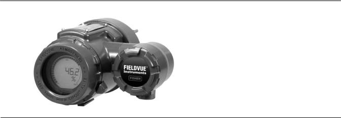
DLC3010 Digital Level Controllers
DLC3010 digital level controllers (figure 1 1) are used with level sensors to measure liquid level, the level of interface between two liquids, or liquid specific gravity (density). Changes in level or specific gravity exert a buoyant force on a
3
Introduction and Specifications |
Instruction Manual |
October 2014 |
D102748X012 |
|
|
displacer, which rotates the torque tube shaft. This rotary motion is applied to the digital level controller, transformed to an electrical signal and digitized. The digital signal is compensated and processed per user configuration requirements, and converted back to a 4 20 mA analog electrical signal. The resulting current output signal is sent to an indicating or final control element.
Figure 1 1. FIELDVUE DLC3010 Digital Level Controller
W7977-1
DLC3010 digital level controllers are communicating, microprocessor based level, interface, or density sensing instruments. In addition to the normal function of providing a 4 20 milliampere current signal, DLC3010 digital level controllers, using the HARTR communications protocol, give easy access to information critical to process operation. You can gain information from the process, the instrument, or the sensor using a Field Communicator with device descriptions (DDs) compatible with DLC3010 digital level controllers. The Field Communicator may be connected at the digital level controller or at a field junction box.
Using the Field Communicator, you can perform several operations with the DLC3010 digital level controller. You can interrogate, configure, calibrate, or test the digital level controller. Using the HART protocol, information from the field can be integrated into control systems or be received on a single loop basis.
DLC3010 digital level controllers are designed to directly replace standard pneumatic and electro pneumatic level transmitters. DLC3010 digital level controllers mount on a wide variety of caged and cageless 249 level sensors. They mount on other manufacturers' displacer type level sensors through the use of mounting adaptors.
249 Caged Sensors (see table 1 6)
D 249, 249B, 249BF, 249C, 249K, and 249L sensors side mount on the vessel with the displacer mounted inside a cage outside the vessel. (The 249BF caged sensor is available only in Europe, Middle East, and Africa.)
249 Cageless Sensors (see table 1 7)
D 249BP, 249CP, and 249P sensors top mount on the vessel with the displacer hanging down into the vessel.
D 249VS sensor side mounts on the vessel with the displacer hanging out into the vessel.
D 249W wafer style sensor mounts on top of a vessel or on a customer supplied cage.
Specifications
Specifications for the DLC3010 digital level controller are shown in table 1 1. Specifications for the 249 sensor are shown in table 1 3. Specifications for the Field Communicator can be found in the Product Manual for the Field Communicator.
4
Instruction Manual |
Introduction and Specifications |
D102748X012 |
October 2014 |
|
|
Related Documents
Other documents containing information related to the DLC3010 digital level controller and 249 sensors include:
D Bulletin 11.2:DLC3010 - FIELDVUE DLC3010 Digital Level Controller (D102727X012)
D FIELDVUE DLC3010 Digital Level Controller Quick Start Guide (D103214X012)
D Using FIELDVUE Instruments with the Smart HART Loop Interface and Monitor (HIM) (D103263X012)
D Audio Monitor for HART Communications (D103265X012)
D Fisher 249 Caged Displacer Sensors Instruction Manual (D200099X012)
D Fisher 249 Cageless Displacer Sensors Instruction Manual (D200100X012)
D Fisher 249VS Cageless Displacer Sensor Instruction Manual (D103288X012)
D Fisher 249W Cageless Wafer Style Level Sensor Instruction Manual (D102803X012)
D Simulation of Process Conditions for Calibration of Fisher Level Controllers and Transmitters (D103066X012)
D Bolt Torque Information (D103220X012)
D Technical Monograph 7: The Dynamics of Level and Pressure Control
D Technical Monograph 18: Level Trol Density Transmitter
D Technical Monograph 26: Guidelines for Selection of Liquid Level Control Equipment
These documents are available from your Emerson Process Management sales office. Also visit our website at www.Fisher.com.
Educational Services
For information on available courses for the DLC3010 digital level controller, as well as a variety of other products, contact:
Emerson Process Management Educational Services, Registration
Phone: +1-641-754-3771 or +1-800-338-8158 e mail: education@emerson.com http://www.emersonprocess.com/education
5

Introduction and Specifications |
Instruction Manual |
October 2014 |
D102748X012 |
|
|
Table 1 1. DLC3010 Digital Level Controller Specifications |
|
|
|
Available Configurations
DLC3010 Digital Level Controller:
Mounts on caged and cageless 249 sensors. See tables 1 6 and 1 7 and sensor description.
Function: Transmitter
Communications Protocol: HART
Input Signal
Level, Interface, or Density: Rotary motion of torque tube shaft proportional to changes in liquid level, interface level, or density that change the buoyancy of a displacer.
Process Temperature: Interface for 2 or 3 wire 100 ohm platinum RTD for sensing process temperature, or optional user entered target temperature to permit compensating for changes in specific gravity
Output Signal
Analog: 4 20 milliamperes DC (JÉdirect action—increasing level, interface, or density increases output; or JÉreverse action—increasing level, interface, or density decreases output)
High saturation: 20.5 mA
Low saturation: 3.8 mA
High alarm: 22.5 mA
Low Alarm: 3.7 mA
Only one of the above high/low alarm definitions is available in a given configuration. NAMUR NE 43 compliant when high alarm level is selected.
Digital: HART 1200 Baud FSK (frequency shift keyed)
HART impedance requirements must be met to enable communication. Total shunt impedance across the master device connections (excluding the master and transmitter impedance) must be between 230 and 1100 ohms. The transmitter HART receive impedance is defined as:
Rx: 42K ohms and Cx: 14 nF
Note that in point to point configuration, analog and digital signalling are available. The instrument may be queried digitally for information, or placed in Burst mode to regularly transmit unsolicited process information digitally. In multi drop mode, the output current is fixed at 4 mA, and only digital communication is available.
Performance
|
DLC3010 |
w/ NPS 3 |
|
|
Performance |
249W, Using |
w/ All Other |
||
Digital Level |
||||
Criteria |
a 14 inch |
249 Sensors |
||
Controller(1) |
||||
|
Displacer |
|
||
|
|
|
||
Independent |
$0.25% of |
$0.8% of |
$0.5% of |
|
Linearity |
output span |
output span |
output span |
|
|
|
|
|
|
Hysteresis |
<0.2% of |
- - - |
- - - |
|
output span |
||||
|
|
|
||
|
|
|
|
|
Repeatability |
$0.1% of full |
$0.5% of |
$0.3% of |
|
scale output |
output span |
output span |
||
|
||||
|
|
|
|
|
Dead Band |
<0.05% of |
- - - |
- - - |
|
input span |
||||
|
|
|
||
|
|
|
|
|
Hysteresis plus |
- - - |
<1.0% of |
<1.0% of |
|
Deadband |
output span |
output span |
||
|
||||
|
|
|
|
NOTE: At full design span, reference conditions. 1. To lever assembly rotation inputs.
At effective proportional band (PB)<100%, linearity, dead band, and repeatability are derated by the factor (100%/PB)
Operating Influences
Power Supply Effect: Output changes <±0.2% of full scale when supply varies between min. and max voltage specifications.
Transient Voltage Protection: The loop terminals are protected by a transient voltage suppressor. The specifications are as follows:
Pulse Waveform |
Max VCL |
Max IPP |
|
Rise Time |
Decay to |
(Clamping |
(Pulse Peak |
(ms) |
50% (ms) |
Voltage) (V) |
@ Current) (A) |
10 |
1000 |
93.6 |
16 |
|
|
|
|
8 |
20 |
121 |
83 |
|
|
|
|
Note: μs = microsecond
Ambient Temperature: The combined temperature effect on zero and span without the 249 sensor is less than 0.03% of full scale per degree Kelvin over the operating range -40 to 80_C (-40 to 176_F)
Process Temperature: The torque rate is affected by the process temperature (see figure 1 2). The process density may also be affected by the process temperature.
Process Density: The sensitivity to error in knowledge of process density is proportional to the differential density of the calibration. If the differential specific gravity is 0.2, an error of 0.02 specific gravity units in knowledge of a process fluid density represents 10% of span.
-continued-
6

Instruction Manual |
Introduction and Specifications |
D102748X012 |
October 2014 |
|
|
Table 1 1. DLC3010 Digital Level Controller Specifications (continued) |
|
Electromagnetic Compatibility
Meets EN 61326 1 and EN 61326 2 3 ÃImmunity—Industrial locations per Table 2 of ÃÃEN 61326 1 and Table AA.2 of EN 61326 2 3. ÃÃPerformance is shown in table 1 2 below. ÃEmissions—Class A
ÃÃISM equipment rating: Group 1, Class A
Supply Requirements (See figure 2 10)
12 to 30 volts DC; instrument has reverse polarity protection.
A minimum compliance voltage of 17.75 is required to guarantee HART communication.
Compensation
Transducer compensation: for ambient temperature. Density parameter compensation: for process temperature (requires user supplied tables).
Manual compensation: for torque tube rate at target process temperature is possible.
Digital Monitors
Linked to jumper selected Hi (factory default) or Lo analog alarm signal:
Torque tube position transducer: Drive monitor and signal reasonableness monitor
User configurable alarms: Hi Hi and Lo Lo Limit process alarms
HART readable only:
RTD signal reasonableness monitor: When RTD installed
Processor free time monitor.
Writes remaining in Non Volatile Memory monitor. User configurable alarms: Hi and Lo limit process alarms, Hi and Lo limit process temperature alarms, and Hi and Lo limit electronics temperature alarms
Diagnostics
Output loop current diagnostic. LCD meter diagnostic.
Spot specific gravity measurement in level mode: used to update specific gravity parameter to improve process measurement
Digital signal tracing capability: by review of “troubleshooting variables”, and
Basic trending capability for PV, TV and SV.
LCD Meter Indications
LCD meter indicates analog output on a percent scale bar graph. The meter also can be configured to display:
Process variable in engineering units only. Percent range only.
Percent range alternating with process variable or Process variable, alternating with process temperature (and degrees of pilot shaft rotation).
Electrical Classification
Hazardous Area:
CSA— Intrinsically Safe, Explosion proof, Division 2, Dust Ignition proof
FM— Intrinsically Safe, Explosion proof, Non incendive, Dust Ignition proof
ATEX— Intrinsically Safe, Type n, Flameproof IECEx— Intrinsically Safe, Type n, Flameproof
Electrical Housing:
CSA— Type 4X |
ATEX— IP66 |
FM— NEMA 4X |
IECEx— IP66 |
Other Classifications/Certifications
FSETAN—Russian - Federal Service of Technological, Ecological and Nuclear Inspectorate
GOST R—Russian GOST R
INMETRO— National Institute of Metrology, Standardization, and Industrial Quality (Brazil)
NEPSI— National Supervision and Inspection Centre for Explosion Protection and Safety of Instrumentation (China)
PESO CCOE— Petroleum and Explosives Safety Organisation - Chief Controller of Explosives (India)
TIIS— Technology Institution of Industrial Safety (Japan)
Contact your Emerson Process Management sales office for classification/certification specific information
Minimum Differential Specific Gravity
With a nominal 4.4 degrees torque tube shaft rotation for a 0 to 100 percent change in liquid level (specific gravity=1), the digital level controller can be adjusted to provide full output for an input range of 5% of nominal input span. This equates to a minimum differential specific gravity of 0.05 with standard volume displacers.
-continued-
7

Introduction and Specifications |
Instruction Manual |
October 2014 |
D102748X012 |
|
|
Table 1 1. DLC3010 Digital Level Controller Specifications (continued) |
|
|
|
Minimum Differential Specific Gravity (continued)
See 249 sensor specifications for standard displacer volumes and standard wall torque tubes. Standard volume for 249C and 249CP sensors is 980 cm3 (60 in3), most others have standard volume of 1640 cm3 (100 in3).
Operating at 5% proportional band will degrade accuracy by a factor of 20. Using a thin wall torque tube, or doubling the displacer volume will each roughly double the effective proportional band. When proportional band of the system drops below 50%, changing displacer or torque tube should be considered if high accuracy is a requirement.
Mounting Positions
Digital level controllers can be mounted right or left of displacer, as shown in figure 2 5.
Instrument orientation is normally with the coupling access door at the bottom, to provide proper drainage of lever chamber and terminal compartment, and to limit gravitational effect on the lever assembly. If alternate drainage is provided by user, and a small performance loss is acceptable, the instrument could be mounted in 90 degree rotational increments around the pilot shaft axis. The LCD meter may be rotated in 90 degree increments to accommodate this.
Construction Materials
Case and Cover: Low copper aluminum alloy Internal: Plated steel, aluminum, and stainless steel;
encapsulated printed wiring boards; Neodymium Iron Boron Magnets
Electrical Connections
Two 1/2 14 NPT internal conduit connections; one on bottom and one on back of terminal box. M20 adapters available.
Options
JHeat insulator. See description under Ordering Information. J Mountings for Masoneilant, Yamatake, and Foxborot Eckhardt displacers available. J Level Signature Series Test (Performance Validation Report) available (EMA only) for instruments factory mounted on 249 sensor.
JFactory Calibration: available for instruments factory mounted on 249 sensor, when application, process temperature and density(s) are supplied.
JDevice is compatible with user specified remote indicator.
Operating Limits
Process Temperature: See table 1 4 and figure 2 7.
Ambient Temperature and Humidity: See below
Conditions |
Normal |
Transport and |
Nominal |
|
Limits(1,2) |
Storage Limits |
Reference |
||
|
||||
Ambient |
-40 to 80_C |
-40 to 85_C |
25_C |
|
Temperature |
(-40 to 176_F) |
(-40 to 185_F) |
(77_F) |
|
|
|
|
|
|
Ambient |
0 to 95%, |
0 to 95%, |
|
|
Relative |
40% |
|||
(non condensing) |
(non condensing) |
|||
Humidity |
|
|||
|
|
|
||
|
|
|
|
Weight
Less than 2.7 Kg (6 lbs)
NOTE: Specialized instrument terms are defined in ANSI/ISA Standard 51.1 - Process Instrument Terminology.
1.LCD meter may not be readable below -20_C (-4_F)
2.Contact your Emerson Process Management sales office or application engineer if temperatures exceeding these limits are required.
Table 1 2. EMC Summary Results—Immunity
Port |
Phenomenon |
Basic Standard |
Test Level |
Performance |
|
Criteria(1)(2) |
|
||||
|
|
|
|
|
|
|
Electrostatic discharge (ESD) |
IEC 61000 4 2 |
4 kV contact |
A |
|
|
8 kV air |
||||
|
|
|
|
|
|
|
|
|
|
|
|
|
|
|
80 to 1000 MHz @ 10V/m with 1 kHz AM at 80% |
|
|
Enclosure |
Radiated EM field |
IEC 61000 4 3 |
1400 to 2000 MHz @ 3V/m with 1 kHz AM at 80% |
A |
|
|
|
|
2000 to 2700 MHz @ 1V/m with 1 kHz AM at 80% |
|
|
|
|
|
|
|
|
|
Rated power frequency |
IEC 61000 4 8 |
60 A/m at 50 Hz |
A |
|
|
magnetic field |
||||
|
|
|
|
|
|
|
|
|
|
|
|
|
Burst |
IEC 61000 4 4 |
1 kV |
A |
|
|
|
|
|
|
|
I/O signal/control |
Surge |
IEC 61000 4 5 |
1 kV (line to ground only, each) |
B |
|
|
|
|
|
|
|
|
Conducted RF |
IEC 61000 4 6 |
150 kHz to 80 MHz at 3 Vrms |
A |
|
|
|
|
|
|
|
Note: RTD wiring must be shorter than 3 meters (9.8 feet)
1. A = No degradation during testing. B = Temporary degradation during testing, but is self recovering. Specification limit = +/- 1% of span.
2. HART communication was considered as “not relevant to the process” and is used primarily for configuration, calibration, and diagnostic purposes.
8

Instruction Manual |
Introduction and Specifications |
D102748X012 |
October 2014 |
|
|
Figure 1 2. Theoretical Reversible Temperature Effect on Common Torque Tube Materials
TORQUE RATE REDUCTION
(NORMALIZED MODULUS OF RIGIDITY)
Gnorm
1.00 |
|
|
|
|
|
|
|
|
|
|
|
|
|
|
|
|
|
|
|
|
|
|
0.98 |
|
|
|
|
|
|
|
|
|
|
|
|
|
|
|
|
|
|
|
|
|
|
|
|
|
|
|
|
|
|
|
|
|
|
|
|
|
1 |
|
|
|
|
|
|
|
0.96 |
|
|
|
|
|
|
|
|
|
|
|
|
|
|
|
|
|
|
|
|
|
|
0.94 |
|
|
|
|
|
|
|
|
|
|
|
|
|
|
|
|
|
|
|
|
|
|
0.92 |
|
|
|
|
|
|
|
|
|
|
|
|
|
|
|
|
|
|
|
|
|
N05500 |
|
|
|
|
|
|
|
|
|
|
|
|
|
|
|
|
|
|
|
|
|
|
N06600 |
0.90 |
|
|
|
|
|
|
|
|
|
|
|
|
|
|
|
|
|
|
|
|
|
|
|
|
|
|
|
|
|
|
|
|
|
|
|
|
|
|
|
|
|
|
|
|
N10276 |
0.88 |
|
|
|
|
|
|
|
|
|
|
|
|
|
|
|
|
|
|
|
|
|
|
0.86 |
|
|
|
|
|
|
|
|
|
|
|
|
|
|
|
|
|
|
|
|
|
|
0.84 |
|
|
|
|
|
|
|
|
|
|
|
|
|
|
|
|
|
|
|
|
|
|
0.82 |
|
|
|
|
|
|
|
|
|
|
|
|
|
|
|
|
|
|
|
|
|
|
0.80 |
|
|
|
|
|
|
|
|
|
|
|
|
|
|
|
|
|
|
|
|
|
S31600 |
20 |
40 |
60 |
80 |
100 |
120 |
140 |
160 |
180 |
200 |
220 |
240 |
260 |
280 |
300 |
320 |
340 |
360 |
380 |
400 |
420 |
||
TEMPERATURE (_C)
TORQUE RATE REDUCTION
(NORMALIZED MODULUS OF RIGIDITY)
1.00
0.98
1 
0.96
Gnorm
0.94 |
|
|
|
|
|
|
|
|
|
|
|
|
|
|
|
0.92 |
|
|
|
|
|
|
|
|
|
|
|
|
|
|
N05500 |
|
|
|
|
|
|
|
|
|
|
|
|
|
|
|
|
|
|
|
|
|
|
|
|
|
|
|
|
|
|
|
N06600 |
0.90 |
|
|
|
|
|
|
|
|
|
|
|
|
|
|
|
|
|
|
|
|
|
|
|
|
|
|
|
|
|
|
N10276 |
0.88 |
|
|
|
|
|
|
|
|
|
|
|
|
|
|
|
0.86 |
|
|
|
|
|
|
|
|
|
|
|
|
|
|
|
0.84 |
|
|
|
|
|
|
|
|
|
|
|
|
|
|
|
0.82 |
|
|
|
|
|
|
|
|
|
|
|
|
|
|
|
0.80 |
|
|
|
|
|
|
|
|
|
|
|
|
|
|
S31600 |
50 |
100 |
150 |
200 |
250 |
300 |
350 |
400 |
450 |
500 |
550 |
600 |
650 |
700 |
750 |
800 |
TEMPERATURE (_F)
NOTE:
1  DUE TO THE PERMANENT DRIFT THAT OCCURS NEAR AND ABOVE 260_C (500_F), N05500 IS NOT RECOMMENDED FOR TEMPERATURES ABOVE 232_C (450_F).
9

Introduction and Specifications |
Instruction Manual |
|
October 2014 |
D102748X012 |
|
|
|
|
Table 1 3. 249 Sensor Specifications |
|
|
Input Signal |
equalizing connection styles are numbered and are |
|
Liquid Level or Liquid to Liquid Interface Level:From 0 |
shown in figure 1 3. |
|
|
||
to 100 percent of displacer length |
Mounting Positions |
|
Liquid Density: From 0 to 100 percent of |
||
|
||
displacement force change obtained with given |
Most level sensors with cage displacers have a |
|
displacer volume—standard volumes are JÉ980 cm3 |
rotatable head. The head may be rotated through |
|
(60 inches3) for 249C and 249CP sensors or JÉ1640 |
360 degrees to any of eight different positions, as |
|
cm3 (100 inches3) for most other sensors; other |
shown in figure 2 5. |
|
volumes available depending upon sensor |
|
|
construction |
Construction Materials |
|
Sensor Displacer Lengths |
See tables 1 5, 1 6, and 1 7 |
|
|
||
See tables 1 6 and 1 7 footnotes |
Operative Ambient Temperature |
|
Sensor Working Pressures |
See table 1 4 |
|
For ambient temperature ranges, guidelines, and use |
||
|
||
Consistent with applicable ANSI |
of optional heat insulator, see figure 2 7. |
|
pressure/temperature ratings for the specific sensor |
|
|
constructions shown in tables 1 6 and 1 7 |
Options |
|
Caged Sensor Connection Styles |
J Heat insulator, see description under Ordering |
|
Information J Gauge glass for pressures to 29 bar at |
||
|
||
Cages can be furnished in a variety of end connection |
232_C (420 psig at 450_F), and J Reflex gauges for |
|
styles to facilitate mounting on vessels; the |
high temperature and pressure applications |
|
|
|
Table 1 4. Allowable Process Temperatures for Common 249 Sensor Pressure Boundary Materials
MATERIAL |
PROCESS TEMPERATURE |
||
Min. |
Max. |
||
|
|||
Cast Iron |
-29_C (-20_F) |
232_C (450_F) |
|
|
|
|
|
Steel |
-29_C (-20_F) |
427_C (800_F) |
|
|
|
|
|
Stainless Steel |
-198_C (-325_F) |
427_C (800_F) |
|
|
|
|
|
N04400 |
-198_C (-325_F) |
427_C (800_F) |
|
|
|
|
|
Graphite |
|
|
|
Laminate/SST |
-198_C (-325_F) |
427_C (800_F) |
|
Gaskets |
|
|
|
|
|
|
|
N04400/PTFE |
-73_C (-100_F) |
204_C (400_F) |
|
Gaskets |
|||
|
|
||
|
|
|
|
Table 1 5. Displacer and Torque Tube Materials
Part |
Standard Material |
Other Materials |
|
|
|
316 Stainless Steel, |
|
Displacer |
304 Stainless Steel |
N10276, N04400, |
|
Plastic, and Special |
|||
|
|
||
|
|
Alloys |
|
|
|
|
|
Displacer Stem |
|
N10276, N04400, |
|
Driver Bearing, |
316 Stainless Steel |
other Austenitic |
|
Displacer Rod |
Stainless Steels, and |
||
|
|||
and Driver |
|
Special Alloys |
|
|
|
|
|
Torque Tube |
N05500(1) |
316 Stainless Steel, |
|
N06600, N10276 |
|||
|
|
||
|
|
|
1. N05500 is not recommended for spring applications above 232_C (450_F). Contact your Emerson Process Management sales office or application engineer if temperatures exceeding this limit are required.
10
Instruction Manual |
|
|
|
|
Introduction and Specifications |
||||||||
D102748X012 |
|
|
|
|
|
|
|
|
|
|
|
October 2014 |
|
|
|
|
|
|
|
|
|
|
|
|
|
|
|
Table 1 6. Caged Displacer Sensors(1) |
|
|
|
|
|
|
|||||||
TORQUE TUBE |
|
|
|
|
|
STANDARD CAGE, HEAD, |
|
EQUALIZING CONNECTION |
|
|
PRESSURE RATING(2) |
||
|
SENSOR |
|
AND TORQUE TUBE ARM |
|
|
|
|
|
|||||
ORIENTATION |
|
|
|
Style |
|
Size (NPS) |
|||||||
|
|
|
|
|
MATERIAL |
|
|
|
|||||
|
|
|
|
|
|
|
|
|
|||||
|
|
|
|
|
|
|
|
|
|
|
|
||
|
|
249(3) |
|
|
|
Cast iron |
|
Screwed |
|
1 1/2 or 2 |
CL125 or CL250 |
||
|
|
|
|
|
|
|
|
|
|
||||
|
|
|
|
Flanged |
|
2 |
|
||||||
|
|
|
|
|
|
|
|
|
|
|
|
||
|
|
|
|
|
|
|
|
|
|
|
|
|
|
|
|
|
|
|
|
|
|
|
Screwed or optional socket weld |
|
1 1/2 or 2 |
CL600 |
|
|
|
|
|
|
|
|
|
|
|
|
|
|
|
|
|
|
|
|
|
|
|
|
|
|
1 1/2 |
CL150, CL300, or |
|
|
|
249B, 249BF(4) |
|
Steel |
|
Raised face or optional ring type joint |
|
CL600 |
|||||
|
|
|
|
|
|
|
|||||||
Torque tube |
|
|
|
|
|
|
|
|
flanged |
|
2 |
|
CL150, CL300, or |
arm rotatable |
|
|
|
|
|
|
|
|
|
|
|
CL600 |
|
|
|
|
|
|
|
|
|
|
|
|
|
||
with respect to |
|
|
|
|
|
|
|
|
Screwed |
|
1 1/2 or 2 |
CL600 |
|
equalizing |
|
|
|
|
|
|
|
|
|
|
|
|
|
|
|
|
|
|
|
|
|
|
|
1 1/2 |
CL150, CL300, or |
||
connections |
|
|
|
|
|
|
|
|
|
|
|||
|
249C(3) |
|
316 stainless steel |
|
|
|
CL600 |
||||||
|
|
|
Raised face flanged |
|
|
|
|||||||
|
|
|
|
|
|
|
|
|
|
2 |
|
CL150, CL300, or |
|
|
|
|
|
|
|
|
|
|
|
|
|
||
|
|
|
|
|
|
|
|
|
|
|
|
CL600 |
|
|
|
|
|
|
|
|
|
|
|
|
|
|
|
|
|
|
|
|
|
|
|
|
|
|
|
|
|
|
|
249K |
|
Steel |
|
Raised face or optional ring type joint |
|
1 1/2 or 2 |
CL900 or CL1500 |
||||
|
|
|
|
flanged |
|
||||||||
|
|
|
|
|
|
|
|
|
|
|
|
|
|
|
|
|
|
|
|
|
|
|
|
|
|
|
|
|
|
249L |
|
Steel |
|
Ring type joint flanged |
|
2(5) |
CL2500 |
||||
1. Standard displacer lengths for all styles (except 249) are 14, 32, 48, 60, 72, 84, 96, 108 and 120 inches. The 249 uses a displacer with a length of either 14 or 32 inches. |
|||||||||||||
2. EN flange connections available in EMA (Europe, Middle East and Africa). |
|
|
|
|
|
|
|||||||
3. Not available in EMA. |
|
|
|
|
|
|
|
|
|
|
|
|
|
4. The 249BF available in EMA only. Also available in EN size DN 40 with PN 10 to PN 100 flanges and size DN 50 with PN 10 to PN 63 flanges. |
|
|
|
||||||||||
5. Top connection is NPS 1 ring type joint flanged for connection styles F1 and F2. |
|
|
|
|
|
|
|||||||
|
|
|
|
|
|
|
|
|
|
|
|
|
|
Table 1 7. Cageless Displacer Sensors(1) |
|
|
|
|
|
|
|||||||
|
|
|
|
|
Standard Head(2), Wafer |
|
|
|
|
|
|
|
|
Mounting |
Sensor |
|
|
Body(6) and Torque Tube |
|
|
Flange Connection (Size) |
|
Pressure Rating(3) |
||||
|
|
|
|
|
|
Arm Material |
|
|
|
|
|
|
|
|
|
249BP(4) |
|
Steel |
|
NPS 4 raised face or optional ring type joint |
|
CL150, CL300, or CL600 |
|||||
|
|
|
|
|
|
|
|
|
|
||||
|
|
|
|
NPS 6 or 8 raised face |
|
CL150 or CL300 |
|||||||
|
|
|
|
|
|
|
|
|
|||||
|
|
|
|
|
|
|
|
|
|||||
Mounts on |
249CP |
|
316 Stainless Steel |
|
NPS 3 raised face |
|
CL150, CL300, or CL600 |
||||||
|
|
|
|
|
|
|
|
|
|
|
|
||
|
|
|
|
|
|
|
|
|
|
CL900 or 1CL500 |
|||
top of vessel |
|
|
|
|
|
|
NPS 4 raised face or optional ring type joint |
|
|||||
|
|
|
|
|
|
|
(EN PN 10 to DIN PN 250) |
||||||
|
|
249P(5) |
|
Steel or stainless steel |
|
|
|
|
|
||||
|
|
|
|
|
|
|
|
|
|
||||
|
|
|
|
NPS 6 or 8 raised face |
|
CL150, CL300, CL600, CL900, |
|||||||
|
|
|
|
|
|
|
|
|
|||||
|
|
|
|
|
|
|
|
|
CL1500, or CL2500 |
||||
|
|
|
|
|
|
|
|
|
|
|
|
||
|
|
|
|
|
|
|
|
|
|
|
|
|
|
|
|
|
|
|
WCC (steel) LCC (steel), or |
|
|
|
|
|
CL125, CL150, CL250, CL300, |
||
Mounts on |
|
|
|
|
For NPS 4 raised face or flat face |
|
CL600, CL900, or CL1500 |
||||||
249VS |
|
CF8M (316 stainless steel) |
|
|
|||||||||
side of vessel |
|
|
|
|
|
|
(EN PN 10 to DIN PN 160) |
||||||
|
|
|
|
|
|
|
|
||||||
|
|
|
|
|
|
|
|
|
|
||||
|
|
|
|
|
|
|
|
|
|
|
|
||
|
|
|
|
|
WCC, LCC, or CF8M |
|
For NPS 4 buttweld end, XXZ |
|
CL2500 |
|
|||
|
|
|
|
|
|
|
|
|
|
|
|
|
|
Mounts on top of |
|
|
|
WCC or CF8M |
|
For NPS 3 raised face |
|
CL150, CL300, or CL600 |
|||||
vessel or on |
|
|
|
|
|
||||||||
249W |
|
|
|
|
|
|
|
|
|
|
|||
customer |
|
LCC or CF8M |
|
For NPS 4 raised face |
|
CL150, CL300, or CL600 |
|||||||
|
|
|
|
|
|||||||||
supplied cage |
|
|
|
|
|
||||||||
|
|
|
|
|
|
|
|
|
|
|
|
||
|
|
|
|
|
|
|
|
|
|
||||
1. Standard displacer lengths are 14, 32, 48, 60, 72, 84, 96, 108, and 120 inches. |
|
|
|
|
|
|
|||||||
2. Not used with side mounted sensors. |
|
|
|
|
|
|
|
|
|
||||
3. EN flange connections available in EMA (Europe, Middle East and Africa). |
|
|
|
|
|
|
|||||||
4. Not available in EMA. |
|
|
|
|
|
|
|
|
|
|
|
|
|
5. 249P available in EMA only. |
|
|
|
|
|
|
|
|
|
||||
6. Wafer Body only applicable to the 249W. |
|
|
|
|
|
|
|
|
|
||||
11

Introduction and Specifications |
Instruction Manual |
October 2014 |
D102748X012 |
|
|
|
|
Figure 1 3. Style Number of Equalizing Connections |
|
STYLE 1 |
AND LOWER SIDE CONNECTIONS, |
|
TOP AND BOTTOM CONNECTIONS, |
||
SCREWED (S 3) OR FLANGED (F 3) |
||
SCREWED (S 1) OR FLANGED (F 1) |
||
|
STYLE 2
TOP AND LOWER SIDE CONNECTIONS,
SCREWED (S 2) OR FLANGED (F 2)
28B5536 1
B1820 2
STYLE 4
UPPER SIDE AND BOTTOM CONNECTIONS, SCREWED (S 4) OR FLANGED (F 4)
12

Instruction Manual |
Installation |
D102748X012 |
October 2014 |
|
|
Section 2 Installation
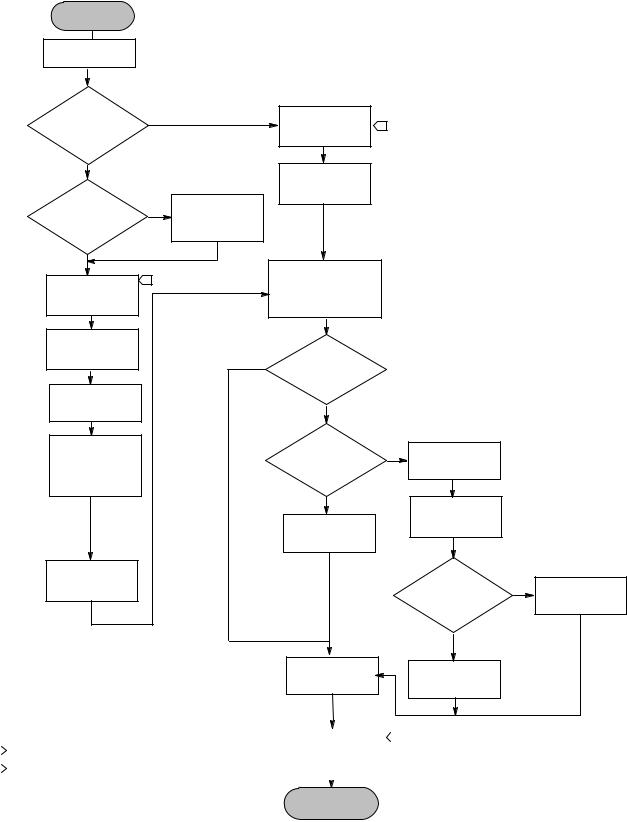
This section contains digital level controller installation information including an installation flowchart (figure 2 1), mounting and electrical installation information, and a discussion of failure mode jumpers.
Configuration: On the Bench or in the Loop
Configure the digital level controller before or after installation. It may be useful to configure the instrument on the bench before installation to ensure proper operation, and to familiarize yourself with its functionality.
Protecting the Coupling and Flexures
CAUTION
Damage to flexures and other parts can cause measurement errors. Observe the following steps before moving the sensor and controller.
Lever Lock
The lever lock is built in to the coupling access handle. When the handle is open, it positions the lever in the neutral travel position for coupling. In some cases, this function is used to protect the lever assembly from violent motion during shipment.
A DLC3010 controller will have one of the following mechanical configurations when received:
1.A fully assembled and coupled caged displacer system shipped with the displacer or driver rod blocked within the operating range by mechanical means. In this case, the access handle (figure 2 4) will be in the unlocked position. Remove the displacer blocking hardware before calibration. (See the appropriate sensor instruction manual). The coupling should be intact.
CAUTION
When shipping an instrument mounted on a sensor, if the lever assembly is coupled to the linkage, and the linkage is constrained by the displacer blocks, use of the lever lock may result in damage to bellows joints or flexure.
2.If the displacer cannot be blocked because of cage configuration or other concerns, the transmitter is uncoupled from the torque tube by loosening the coupling nut, and the access handle will be in the locked position. Before placing such a configuration into service, perform the Coupling procedure found on page 38.
3.For a cageless system where the displacer is not connected to the torque tube during shipping, the torque tube itself stabilizes the coupled lever position by resting against a physical stop in the sensor. The access handle will be in the unlocked position. Mount the sensor and hang the displacer. The coupling should be intact.
13
Installation |
Instruction Manual |
October 2014 |
D102748X012 |
|
|
Figure 2 1. Installation Flowchart
START HERE
Check Alarm
Jumper Position
Factory mounted |
Yes |
|
Wire |
|
|
|
|
|
|
Digital Level |
1 |
|
|
|
|
on 249 sensor? |
|
|
|
|
|
||
|
|
Controller |
|
|
|
||
|
|
|
|
|
|
|
|
No |
|
|
Power |
|
|
|
|
|
|
|
Digital Level |
|
|
|
|
High |
|
|
Controller |
|
|
|
|
Yes |
Install heat |
|
|
|
|
|
|
temperature |
|
|
|
|
|
||
|
insulator |
|
|
|
|
|
|
application? |
|
|
|
|
|
|
|
|
assembly |
|
|
|
|
|
|
|
|
|
|
|
|
|
|
No |
|
|
|
|
|
|
|
|
|
|
Enter Tag, Messages, |
|
|
|
|
Mount and Wire 1 |
|
Date, and check or set |
|
|
|
|
|
Digital level |
|
|
target application data |
|
|
|
|
|
|
|
|
|
|
|
|
Controller |
|
|
|
|
|
|
|
Power |
|
|
|
|
|
|
|
Digital level |
|
|
|
|
|
|
|
Controller |
|
Yes |
Density |
|
|
|
|
|
|
|
Measurement? |
|
|
|
|
Set Level Offset |
|
|
|
|
|
|
|
to Zero |
|
|
No |
|
|
|
|
|
|
|
|
|
|
|
|
Use Setup Wizard |
|
|
Using |
Yes |
Set |
|
|
to enter sensor |
|
|
Temperature |
|
|
||
|
|
|
Temperature |
|
|
||
data and |
|
|
Correction? |
|
|
|
|
|
|
|
Units |
|
|
||
calibration |
|
|
|
|
|
|
|
|
|
|
|
|
|
|
|
condition |
|
|
|
|
|
|
|
|
|
|
No |
|
Setup specific |
|
|
|
|
|
|
|
|
|
|
|
|
|
Set |
|
gravity tables |
|
|
|
|
|
|
|
|
|
|
|
|
|
Specific Gravity |
|
|
|
|
Calibrate |
|
|
|
|
|
|
|
sensor |
|
|
|
|
|
Yes |
Setup and |
|
|
|
|
|
Using RTD? |
|
|
|
|
|
|
|
|
Calibrate RTD |
|
|
|
|
|
|
|
|
|
|
|
|
|
|
No |
|
|
Set
Range Values
Enter Process
Temperature
|
|
|
|
|
|
|
|
|
|
|
|
|
|
|
|
|
NOTE: |
Disable Writes |
|
2 |
|
||
|
|
|
|||||
|
|
|
|
|
|
||
|
1 IF USING RTD FOR TEMPERATURE CORRECTION, |
||||||
|
|
|
|
|
|
||
|
|
|
|
|
|
|
|
|
ALSO WIRE RTD TO DIGITAL LEVEL CONTROLLER |
|
|
|
|
|
|
|
|
|
|
|
|
|
|
|
2 DISABLING WRITES IS EFFECTIVE ONLY IF THE DLC3010 REMAINS |
|
|
|
|
|
|
|
|
|
|
|
|
|
|
|
POWERED UP |
|
|
|
|
|
|
|
|
|
|
|
|
|
|
|
|
|
DONE |
||||
|
|
|
|
|
|
|
|
14

Instruction Manual |
Installation |
D102748X012 |
October 2014 |
|
|
4.If the controller was shipped alone, the access handle will be in the locked position. All Mounting, Coupling and Calibration procedures must be performed.
The access handle includes a retaining set screw, as shown in figures 2 4 and 2 6. The screw is driven in to contact the spring plate in the handle assembly before shipping. It secures the handle in the desired position during shipping and operation. To set the access handle in the open or closed position, this set screw must be backed out so that its top is flush with the handle surface.
Mounting

 WARNING
To avoid personal injury, always wear protective gloves, clothing, and eyewear when performing any installation operations.
Personal injury or property damage due to sudden release of pressure, contact with hazardous fluid, fire, or explosion can be caused by puncturing, heating, or repairing a displacer that is retaining process pressure or fluid. This danger may not be readily apparent when disassembling the sensor or removing the displacer. Before disassembling the sensor or removing the displacer, observe the appropriate warnings provided in the sensor instruction manual.
Check with your process or safety engineer for any additional measures that must be taken to protect against process media.
Hazardous Area Classifications and Special Instructions for “Safe Use” and Installations in Hazardous Locations
Refer to the DLC3010 Quick Start Guide (D103214X012) that ships with the instrument for Hazardous Area Classifications and Special Instructions for “Safe Use” and Installations in Hazardous Locations. If a copy of this quick start guide is needed contact your Emerson Process Management sales office or visit our website at www.Fisher.com.
Mounting the 249 Sensor
The 249 sensor is mounted using one of two methods, depending on the specific type of sensor. If the sensor has a caged displacer, it typically mounts on the side of the vessel as shown in figure 2 2. If the sensor has a cageless displacer, the sensor mounts on the side or top of the vessel as shown in figure 2 3.
The DLC3010 digital level controller is typically shipped attached to the sensor. If ordered separately, it may be convenient to mount the digital level controller to the sensor and perform the initial setup and calibration before installing the sensor on the vessel.
Note
Caged sensors have a rod and block installed on each end of the displacer to protect the displacer in shipping. Remove these parts before installing the sensor to allow the displacer to function properly.
15
Installation |
|
Instruction Manual |
October 2014 |
|
D102748X012 |
|
|
|
|
|
|
Figure 2 2. Typical Caged Sensor Mounting |
|
Figure 2 3. Typical Cageless Sensor Mounting |
A3788 1
A3789 1
Digital Level Controller Orientation
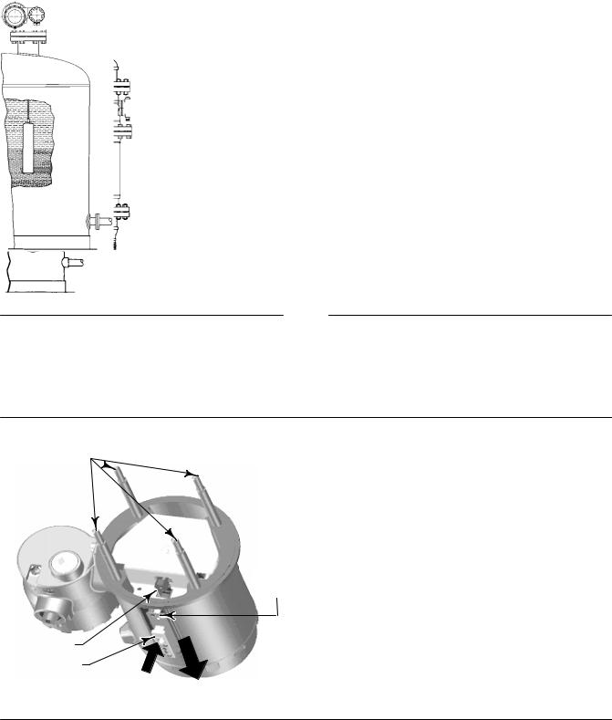
Mount the digital level controller with the torque tube shaft clamp access hole (see figure 2 4) pointing downward to allow accumulated moisture drainage.
Figure 2 4. Sensor Connection Compartment (Adapter Ring Removed for Clarity)
MOUNTING
STUDS 

SHAFT CLAMP
SET SCREW
PRESS HERE TO
MOVE ACCESS
HANDLE
ACCESS
HOLE
SLIDE ACCESS HANDLE TOWARD FRONT OF UNIT TO EXPOSE ACCESS HOLE
16

Instruction Manual |
Installation |
D102748X012 |
October 2014 |
|
|
Note
If alternate drainage is provided by the user, and a small performance loss is acceptable, the instrument could be mounted in 90 degree rotational increments around the pilot shaft axis. The LCD meter may be rotated in 90 degree increments to accommodate this.
The digital level controller and torque tube arm are attached to the sensor either to the left or right of the displacer, as shown in figure 2 5. This can be changed in the field on the 249 sensors (refer to the appropriate sensor instruction manual). Changing the mounting also changes the effective action, because the torque tube rotation for increasing level, (looking at the protruding shaft), is clockwise when the unit is mounted to the right of the displacer and counter clockwise when the unit is mounted to the left of the displacer.
All caged 249 sensors have a rotatable head. That is, the digital level controller can be positioned at any of eight alternate positions around the cage as indicated by the position numbers 1 through 8 in figure 2 5. To rotate the head, remove the head flange bolts and nuts and position the head as desired.
Figure 2 5. Typical Mounting Positions for the FIELDVUE DLC3010 Digital Level Controller on Fisher 249 Sensor
SENSOR |
LEFT OF DISPLACER |
RIGHT OF DISPLACER |
|
|
1 |
|
1 |
1 |
CAGED |
|
|
CAGELESS |
|
|
1 NOT AVAILABLE FOR SIZE NPS 2 CL300 AND CL600 249C SENSOR. |
|
|
19B2787 Rev. D |
|
|
19B6600 Rev. C |
|
|
B1407 2 |
|
|
|
|
17 |
Installation |
Instruction Manual |
October 2014 |
D102748X012 |
|
|
Mounting the Digital Level Controller on a 249 Sensor
Refer to figure 2 4 unless otherwise indicated.
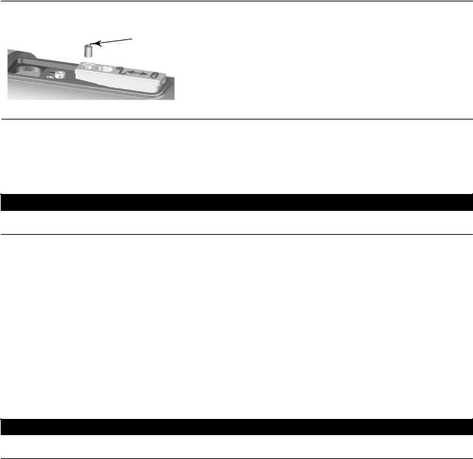
1.If the set screw in the access handle (figure 2 6) is driven against the spring plate, back it out until the head is flush with the outer surface of the handle, using a 2 mm hex key. Slide the access handle to the locked position to expose the access hole. Press on the back of the handle as shown in figure 2 4 then slide the handle toward the front of the unit. Be sure the locking handle drops into the detent.
Figure 2 6. Close up of Set Screw
SET SCREW
2.Using a 10 mm deep well socket inserted through the access hole, loosen the shaft clamp (figure 2 4). This clamp will be re tightened in the Coupling portion of the Initial Setup section.
3.Remove the hex nuts from the mounting studs. Do not remove the adapter ring.
CAUTION
Measurement errors can occur if the torque tube assembly is bent or misaligned during installation.
4.Position the digital level controller so the access hole is on the bottom of the instrument.
5.Carefully slide the mounting studs into the sensor mounting holes until the digital level controller is snug against the sensor.
6.Reinstall the hex nuts on the mounting studs and tighten the hex nuts to 10 NSm (88.5 lbfSin).
Mounting the Digital Level Controller for High Temperature Applications
Refer to figure 2 8 for parts identification except where otherwise indicated.
The digital level controller requires an insulator assembly when temperatures exceed the limits shown in figure 2 7. A torque tube shaft extension is required for a 249 sensor when using an insulator assembly.
CAUTION
Measurement errors can occur if the torque tube assembly is bent or misaligned during installation.
18
Instruction Manual |
Installation |
D102748X012 |
October 2014 |
|
|
Figure 2 7. Guidelines for Use of Optional Heat Insulator Assembly
|
|
|
|
AMBIENT TEMPERATURE (_C) |
|
|
|
PROCESS TEMPERATURE ( C) |
||||||
PROCESS TEMPERATURE ( F) |
-40 |
-30 |
-20 |
-10 |
0 |
10 |
20 |
30 |
40 |
50 |
60 |
70 |
80425 |
|
800 |
|
|
|
|
|
|
|
|
|
|
|
400 |
||
|
|
|
|
|
|
|
|
|
|
|
TOO |
|||
|
|
|
|
HEAT INSULATOR |
|
|
300 |
|||||||
|
|
|
|
|
|
HOT |
||||||||
|
|
|
|
REQUIRED |
|
|
|
|
||||||
400 |
|
|
|
|
|
|
|
200 |
||||||
|
|
|
|
|
|
|
|
|
|
|
||||
|
|
|
|
|
|
|
|
|
|
|
|
100 |
||
0 |
|
|
NO HEAT INSULATOR NECESSARY |
|
0 |
|||||||||
|
|
|
|
|
|
|
|
|
|
|
|
|||
1 |
TOO |
|
HEAT INSULATOR |
|
|
|
|
|
|
-100 |
||||
|
|
|
|
|
|
|
|
-200 |
||||||
-325 |
COLD |
|
REQUIRED |
|
|
|
|
|
|
|
||||
|
|
|
|
|
|
|
160 176 |
|||||||
-40 |
-20 |
0 |
20 |
40 |
60 |
|
80 |
100 |
120 |
140 |
||||
AMBIENT TEMPERATURE (_F)
STANDARD TRANSMITTER
NOTES:
1  FOR PROCESS TEMPERATURES BELOW -29_C (-20_F) AND ABOVE 204_C (400_F) SENSOR MATERIALS MUST BE APPROPRIATE FOR THE PROCESS; SEE TABLE 1 4.
2. IF AMBIENT DEW POINT IS ABOVE PROCESS TEMPERATURE, ICE FORMATION MIGHT CAUSE INSTRUMENT MALFUNCTION AND REDUCE INSULATOR EFFECTIVENESS.
39A4070 B
A5494 1
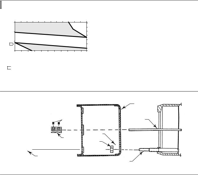
Figure 2 8. Digital Level Controller Mounting on Sensor in High Temperature Applications
MN28800 20A7423 C B2707
|
INSULATOR |
|
(KEY 57) |
|
SHAFT |
SET SCREWS |
EXTENSION |
(KEY 60) |
(KEY 58) |
|
WASHER |
SHAFT |
(KEY 78) |
|
|
COUPLING |
HEX NUTS |
(KEY 59) |
(KEY 34) |
CAP SCREWS |
|
(KEY 63) |
MOUNTING STUDS |
|
|
|
(KEY 33) |
SENSOR |
DIGITAL LEVEL CONTROLLER |
1.For mounting a digital level controller on a 249 sensor, secure the shaft extension to the sensor torque tube shaft via the shaft coupling and set screws, with the coupling centered as shown in figure 2 8.
2.Slide the access handle to the locked position to expose the access hole. Press on the back of the handle as shown in figure 2 4 then slide the handle toward the front of the unit. Be sure the locking handle drops into the detent.
3.Remove the hex nuts from the mounting studs.
4.Position the insulator on the digital level controller, sliding the insulator straight over the mounting studs.
5.Install 4 washers (key 78) over the studs. Install the four hex nuts and tighten.
6.Carefully slide the digital level controller with the attached insulator over the shaft coupling so that the access hole is on the bottom of the digital level controller.
7.Secure the digital level controller and insulator to the torque tube arm with four cap screws.
8.Tighten the cap screws to 10 NSm (88.5 lbfSin).
19
Installation |
Instruction Manual |
October 2014 |
D102748X012 |
|
|
Electrical Connections

 WARNING
Select wiring and/or cable glands that are rated for the environment of use (such as hazardous area, ingress protection and temperature). Failure to use properly rated wiring and/or cable glands can result in personal injury or property damage from fire or explosion.
Wiring connections must be in accordance with local, regional, and national codes for any given hazardous area approval. Failure to follow the local, regional, and national codes could result in personal injury or property damage from fire or explosion.
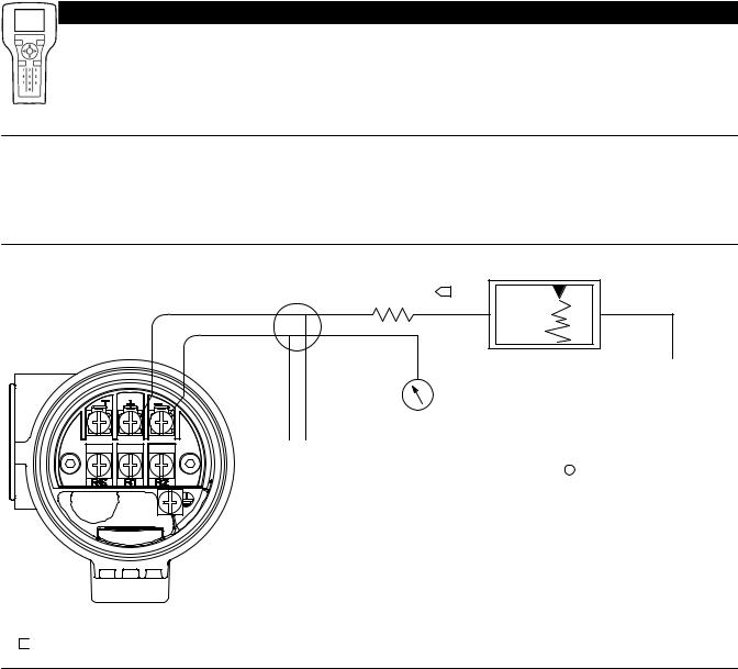
Proper electrical installation is necessary to prevent errors due to electrical noise. A resistance between 230 and 1100 ohms must be present in the loop for communication with a Field Communicator. Refer to figure 2 9 for current loop connections.
Figure 2 9. Connecting a Field Communicator to the Digital Level Controller Loop
230 W 3 RL 3 1100 W |
1 |
+ |
|
− |
|
|
|
+ |
+ |
Reference meter |
|
|
|
|
|
|
|
|
|
|
|
|
|
|
|
|
|
|
|
|
|
|
|
|
||
for calibration |
|
|
|
|
POWER |
||||||||
|
or monitoring |
|
|
|
|
SUPPLY |
|||||||
|
operation. May |
|
|
|
|
|
|
|
|
|
|
|
|
|
be a voltmeter |
|
|
|
|
|
|
|
|
|
|
− |
|
|
|
|
|
|
|
|
|
|
|
|
|||
− |
across 250 ohm |
|
|
|
|
|
|
|
|
|
|
|
|
|
resistor or a |
|
|
|
|
|
|
|
|
|
|
|
|
|
current meter. + |
|
|
|
− |
|
|
|
|
||||
|
|
|
|
|
|
|
|
|
|
|
|
|
|
|
|
|
|
|
|
|
|
|
|
|
|
|
|
|
|
|
|
|
|
|
|
|
|
|
|
|
|
A Field Communicator may be connected at any
termination point in the signal loop. Signal loop must have between 250 and 1100 ohms load for communication.
Signal loop may be grounded at any point or left ungrounded.
NOTE:
1 THIS REPRESENTS THE TOTAL SERIES LOOP RESISTANCE.
E0363
Power Supply
To communicate with the digital level controller, you need a 17.75 volt DC minimum power supply. The power supplied to the transmitter terminals is determined by the available supply voltage minus the product of the total loop resistance and the loop current. The available supply voltage should not drop below the lift off voltage. (The lift off voltage is the minimum “available supply voltage” required for a given total loop resistance). Refer to figure 2 10 to
20
Instruction Manual |
Installation |
D102748X012 |
October 2014 |
|
|
determine the required lift off voltage. If you know your total loop resistance you can determine the lift off voltage. If you know the available supply voltage, you can determine the maximum allowable loop resistance.
Figure 2 10. Power Supply Requirements and Load Resistance
Maximum Load = 43.5 X (Available Supply Voltage - 12.0)
783 |
|
|
|
|
|
Load (Ohms) |
|
|
|
Operating |
|
|
|
|
|
|
|
250 |
|
|
|
Region |
|
|
|
|
|
|
|
0 |
|
|
|
|
|
10 |
12 |
15 |
20 |
25 |
30 |
LIFT OFF SUPPLY VOLTAGE (VDC)
If the power supply voltage drops below the lift off voltage while the transmitter is being configured, the transmitter may output incorrect information.
The DC power supply should provide power with less than 2% ripple. The total resistance load is the sum of the resistance of the signal leads and the load resistance of any controller, indicator, or related pieces of equipment in the loop. Note that the resistance of intrinsic safety barriers, if used, must be included.
Field Wiring
Note
For intrinsically safe applications, refer to the instructions supplied by the barrier manufacturer.

 WARNING
To avoid personal injury or property damage caused by fire or explosion, remove power to the instrument before removing the digital level controller cover in an area which contains a potentially explosive atmosphere or has been classified as hazardous.
All power to the digital level controller is supplied over the signal wiring. Signal wiring need not be shielded, but use twisted pairs for best results. Do not run unshielded signal wiring in conduit or open trays with power wiring, or near heavy electrical equipment. If the digital controller is in an explosive atmosphere, do not remove the digital level controller covers when the circuit is alive, unless in an intrinsically safe installation. Avoid contact with leads and terminals. To power the digital level controller, connect the positive power lead to the + terminal and the negative power lead to the - terminal as shown in figure 2 11.
21
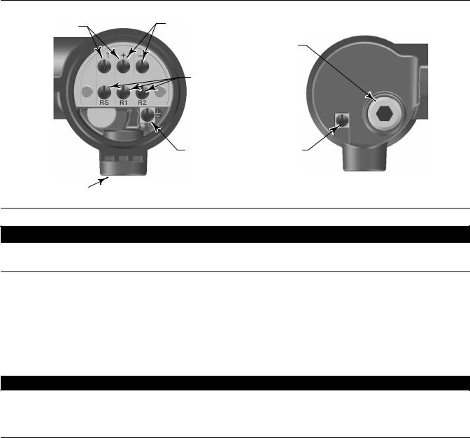
Installation |
Instruction Manual |
October 2014 |
D102748X012 |
|
|
Figure 2 11. Digital Level Controller Terminal Box
TEST CONNECTIONS |
4 20 mA LOOP |
1/2 NPT |
|
CONNECTIONS |
|||
|
|||
|
CONDUIT |
||
|
|
||
|
|
CONNECTION |
|
|
RTD |
|
|
|
CONNECTIONS |
|
|
|
INTERNAL |
EXTERNAL |
|
|
GROUND |
GROUND |
1/2 NPT |
|
CONNECTION |
CONNECTION |
|
|
|
|
CONDUIT |
|
FRONT VIEW |
|
CONNECTION |
|
REAR VIEW |
|
|
|
W8041
CAUTION
Do not apply loop power across the T and + terminals. This can destroy the 1 Ohm sense resistor in the terminal box. Do not apply loop power across the Rs and — terminals. This can destroy the 50 Ohm sense resistor in the electronics module.
When wiring to screw terminals, the use of crimped lugs is recommended. Tighten the terminal screws to ensure that good contact is made. No additional power wiring is required. All digital level controller covers must be fully engaged to meet explosion proof requirements. For ATEX approved units, the terminal box cover set screw must engage one of the recesses in the terminal box beneath the terminal box cover.
Grounding

 WARNING
Personal injury or property damage can result from fire or explosion caused by the discharge of static electricity when flammable or hazardous gases are present. Connect a 14 AWG (2.1 mm2) ground strap between the digital level controller and earth ground when flammable or hazardous gases are present. Refer to national and local codes and standards for grounding requirements.
The digital level controller will operate with the current signal loop either floating or grounded. However, the extra noise in floating systems affects many types of readout devices. If the signal appears noisy or erratic, grounding the current signal loop at a single point may solve the problem. The best place to ground the loop is at the negative terminal of the power supply. As an alternative, ground either side of the readout device. Do not ground the current signal loop at more than one point.
Shielded Wire
Recommended grounding techniques for shielded wire usually call for a single grounding point for the shield. You can either connect the shield at the power supply or to the grounding terminals, either internal or external, at the instrument terminal box shown in figure 2 11.
22

Instruction Manual |
Installation |
D102748X012 |
October 2014 |
|
|
Power/Current Loop Connections
Use ordinary copper wire of sufficient size to ensure that the voltage across the digital level controller terminals does not go below 12.0 volts DC. Connect the current signal leads as shown in figure 2 9. After making connections, recheck the polarity and correctness of connections, then turn the power on.
RTD Connections
An RTD that senses process temperatures may be connected to the digital level controller. This permits the instrument to automatically make specific gravity corrections for temperature changes. For best results, locate the RTD as close to the displacer as practical. For optimum EMC performance, use shielded wire no longer than 3 meters (9.8 feet) to connect the RTD. Connect only one end of the shield. Connect the shield to either the internal ground connection in the instrument terminal box or to the RTD thermowell. Wire the RTD to the digital level controller as follows (refer to figure 2 11):
Two Wire RTD Connections
1.Connect a jumper wire between the RS and R1 terminals in the terminal box.
2.Connect the RTD to the R1 and R2 terminals.
Three Wire RTD Connections
1.Connect the 2 wires which are connected to the same end of the RTD to the RS and R1 terminals in the terminal box. Usually these wires are the same color.
2.Connect the third wire to terminal R2. (The resistance measured between this wire and either wire connected to terminal RS or R1 should read an equivalent resistance for the existing ambient temperature. Refer to the RTD manufacturer's temperature to resistance conversion table.) Usually this wire is a different color from the wires connected to the RS and R1 terminals.
Communication Connections

 WARNING
Personal injury or property damage caused by fire or explosion may occur if this connection is attempted in an area which contains a potentially explosive atmosphere or has been classified as hazardous. Confirm that area classification and atmosphere conditions permit the safe removal of the terminal box cap before proceeding.
The Field Communicator interfaces with digital level controller from any wiring termination point in the 4–20 mA loop (except across the power supply). If you choose to connect the HART communicating device directly to the instrument, attach the device to the loop + and - terminals inside the terminal box to provide local communications with the instrument.
Test Connections

 WARNING
Personal injury or property damage caused by fire or explosion may occur if the following procedure is attempted in an area which contains a potentially explosive atmosphere or has been classified as hazardous. Confirm that area classification and atmosphere conditions permit the safe removal of the terminal box cap before proceeding.
23
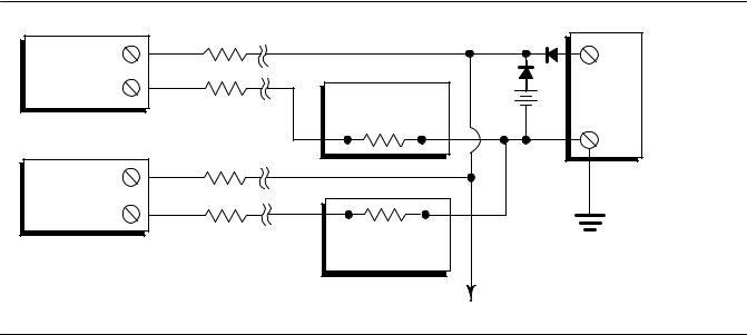
Installation |
Instruction Manual |
October 2014 |
D102748X012 |
|
|
Test connections inside the terminal box can be used to measure loop current across an internal 1 ohm resistor.
1.Remove the terminal box cap.
2.Adjust the test meter to measure a range of 0.001 to 0.1 volts.
3.Connect the positive lead of the test meter to the + connection and the negative lead to the T connection inside the terminal box.
4.Measure Loop current as:
Voltage (on test meter) 1000 = milliamps
example:
Test meter Voltage X 1000 = Loop Milliamps
0.004 X1000 = 4.0 milliamperes
0.020 X 1000 = 20.0 milliamperes
5. Remove test leads and replace the terminal box cover.
Multichannel Installations
You can connect several instruments to a single master power supply as shown in figure 2 12. In this case, the system may be grounded only at the negative power supply terminal. In multichannel installations where several instruments depend on one power supply, and the loss of all instruments would cause operational problems, consider an uninterruptible power supply or a back up battery. The diodes shown in figure 2 12 prevent unwanted charging or discharging of the back up battery. If several loops are connected in parallel, make sure the net loop impedance does not reach levels that would prevent communication.
Figure 2 12. Multichannel Installations |
|
|
|
|
RLead |
|
|
|
|
++ |
|
|
|
+ |
Instrument |
|
|
|
|
No. 1 |
|
|
+ |
|
- |
|
|
DC Power |
|
|
|
|
||
RLead |
Readout |
|
|
Supply |
Device No. 1 |
Battery |
- |
|
|
|
|
Backup |
|
|
|
|
|
|
- |
Instrument |
+ |
|
RLead |
||
No. 2 |
||
|
- |
RLead |
Readout |
Device No. 2
To Additional
Between Instruments
E0364
230 and 1100 W if no Load Resistor
Note that to provide a 4 20 mA analog output signal, the DLC3010 must use HART polling address 0. Therefore, if a multichannel installation is used with all transmitters in 4 20 mA output mode, some means must be provided to isolate an individual transmitter for configuration or diagnostic purposes. A multichannel installation is most useful if the instruments are also in multi drop mode and all signaling is done by digital polling.
24

Instruction Manual |
Installation |
D102748X012 |
October 2014 |
|
|
Alarm Jumper
Each digital level controller continuously monitors its own performance during normal operation. This automatic diagnostic routine is a timed series of checks repeated continuously. If diagnostics detect a failure in the electronics, the instrument drives its output to either below 3.70 mA or above 22.5 mA, depending on the position (HI/LO) of the alarm jumper.
An alarm condition occurs when the digital level controller self diagnostics detect an error that would render the process variable measurement inaccurate, incorrect, or undefined, or a user defined threshold is violated. At this point the analog output of the unit is driven to a defined level either above or below the nominal 4 20 mA range, based on the position of the alarm jumper.
On encapsulated electronics 14B5483X042 and earlier, if the jumper is missing, the alarm is indeterminate, but usually behaves as a FAIL LOW selection. On encapsulated electronics 14B5483X052 and later, the behavior will default to FAIL HIGH when the jumper is missing.
Alarm Jumper Locations
Without a meter installed
The alarm jumper is located on the front side of the electronics module on the electronics side of the digital level controller housing, and is labeled FAIL MODE.
With a meter installed
The alarm jumper is located on the LCD faceplate on the electronics module side of the digital level controller housing, and is labeled FAIL MODE.
Changing Jumper Position

 WARNING
Personal injury or property damage caused by fire or explosion may occur if the following procedure is attempted in an area which contains a potentially explosive atmosphere or has been classified as hazardous. Confirm that area classification and atmosphere conditions permit the safe removal of the instrument cover before proceeding.
Use the following procedure to change the position of the alarm jumper:
1.If the digital level controller is installed, set the loop to manual.
2.Remove the housing cover on the electronics side. Do not remove the cover in explosive atmospheres when the circuit is alive.
3.Set the jumper to the desired position.
4.Replace the cover. All covers must be fully engaged to meet explosion proof requirements. For ATEX approved units, the set screw on the transducer housing must engage one of the recesses in the cover.
25
Installation |
Instruction Manual |
October 2014 |
D102748X012 |
|
|
Loop Test
Field Communicator |
Service Tools > Maintenance > Tests > Loop Test (3-3-1-1) or (3-3-1-2) if LCD Configuration is installed |
|
|
Loop test can be used to verify the controller output, the integrity of the loop, and the operations of any recorders or similar devices installed in the loop. To initiate a loop test, perform the following procedure:
1.Connect a reference meter to the controller. To do so, either connect the meter to the test connections inside the terminal box (see the Test Connections procedure) or connect the meter in the loop as shown in figure 2 9.
2.Access Loop Test.
3.Select OK after you set the control loop to manual.
The Field Communicator displays the loop test menu.
4.Select a discreet milliamp level for the controller to output. At the “Choose analog output” prompt, select 4 mA, 20 mA, or Other to manually input a value between 4 and 20 milliamps.
5.Check the reference meter to verify that it reads the value you commanded the controller to output. If the readings do not match, either the controller requires an output trim, or the meter is malfunctioning.
After completing the test procedure, the display returns to the loop test screen and allows you to choose another output value or end the test.
26
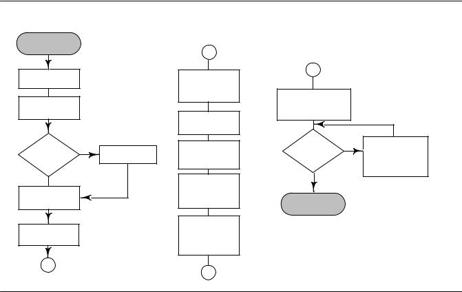
Instruction Manual |
Installation |
D102748X012 |
October 2014 |
|
|
Installation in Conjunction with a Rosemount 333 HART Tri Loop HART to Analog Signal Converter
Use the DLC3010 digital level controller in operation with a Rosemount 333 HART Tri-Loop HART to Analog Signal Converter to acquire an independent 4 20 mA analog output signal for the process variable, % range, electronics temperature, and process temperature. The Tri Loop divides the digital signal and outputs any or all of these variables into as many as three separate 4 20 mA analog channels.
Refer to figure 2 13 for basic installation information. Refer to the 333 HART Tri Loop HART to Analog Signal Converter Product Manual for complete installation information.
Figure 2 13. HART Tri Loop Installation Flowchart
START HERE
Unpack the
HART Tri Loop
Review the
HART Tri Loop
Product Manual
Digital level |
No |
Install the digital |
controller |
|
|
|
level controller. |
|
Installed? |
|
|
|
|
Yes
Set the digital level controller Burst Option
Set the digital level controller Burst Mode
Install the HART
Tri Loop. See
HART Tri Loop
Product Manual
Mount the HART Tri Loop to the DIN rail.
Wire the digital level controller to the HART Tri Loop.
Install Channel 1 wires from HART Tri Loop to the control room.
(Optional) Install Channel
2 and3 wires from HART Tri Loop to the control room.
Configure the HART Tri Loop to receive digital level controller burst commands
Pass system |
No |
Check |
|
troubleshooting |
|||
|
|||
test? |
|
procedures in HART |
|
|
|
Tri Loop product |
|
Yes |
|
manual. |
|
|
|
||
DONE |
|
|
E0365
27
Installation |
Instruction Manual |
October 2014 |
D102748X012 |
|
|
Commissioning the Digital Level Controller for use with the HART Tri Loop
To prepare the digital level controller for use with a 333 HART Tri Loop, you must configure the digital level controller to burst mode, and select the dynamic variables to burst. In burst mode, the digital level controller provides digital information to the HART Tri Loop HART to Analog Signal Converter. The HART Tri Loop converts the digital information to a 4 20 mA analog signal. The HART Tri Loop divides the signal into separate 4 20 mA loops for the primary (PV), secondary (SV), tertiary (TV), and quaternary (QV) variables. Depending upon the burst option selected, the digital level controller will burst the variables as shown in table 2 1.
The DLC3010 status words are available in the HART Burst messages. However, the Tri Loop cannot be configured to monitor them directly.
To commission a DLC3010 digital level controller for use with a HART Tri Loop, perform the following procedure.
Table 2 1. Burst Variables Sent by the FIELDVUE DLC3010
Burst Option |
Variable |
Variable Burst(1) |
Burst Command |
|
Read PV |
Primary |
Process variable (EU) |
1 |
|
|
|
|
|
|
Read PV mA and % Range |
Primary |
Process variable (mA) |
2 |
|
|
|
|||
Secondary |
Percent range (%) |
|||
|
|
|||
|
|
|
|
|
|
Primary |
Process variable (EU) |
|
|
|
|
|
|
|
Read Dynamic Vars |
Secondary |
Electronics temperature (EU) |
3 |
|
|
|
|||
Tertiary |
Process temperature (EU) |
|||
|
|
|||
|
|
|
|
|
|
Quaternary |
Not used |
|
|
|
|
|
|
1. EU—engineering units; mA—current in milliamperes; %—percent
Set the Burst Operation
Field Communicator Configure > Communications > Burst Option (2-4-2)
1.Access Burst Option.
2.Select the desired burst option and press ENTER
3.Access Burst Mode and select On to enable burst mode. Press ENTER.
4.Select SEND to download the new configuration information to the digital level controller.
28
Instruction Manual |
Overview |
D102748X012 |
October 2014 |
|
|
Section 3 Overview
Overview
Field Communicator |
Overview (1) |
|
|
Device Status
Good there are no active alerts and instrument is In Service
Failed a failed alert is active
Maintenance a configured maintenance alert is active and a failed alert is turned on
Advisory a configured advisory alert is active and configured failed or a maintenance alert is turned on
Comm Status
Polled communication with Digital Level Controller is established. Burst mode is turned off.
Burst provides continuous communication from the digital level controller. Burst mode applies only to the transmission of burst mode data and does not affect the way other data is accessed.
PV is
Indicates the type of measurement either level, interface (the interface of two liquids of different specific gravities), or density (measures the liquid specific gravity). The process variable displayed and measured depends on the entry for “PV is” under PV Setup.
Primary Variable
PV Value displays the process variable (level, interface, or density) in engineering units.
% Range displays the process variable as a percent of span (determined by the LRV and URV).
AO
Indicates the current analog output value of the instrument, in milliamperes.
29
Overview |
Instruction Manual |
October 2014 |
D102748X012 |
|
|
Process Temperature
Proc Temp Source— Manual or RTD
Proc Temp— indicates the process temperature.
Device Information
Identification
Follow the prompts on the Field Communicator display to view the following information.
D HART Tag— a unique name (up to eight characters) that identifies the physical instrument.
D Distributor— identifies the distributor of the instrument.
D Model— identifies the instrument model; ie. DLC3010.
D Device ID— each instrument has a unique Device Identifier. The Device ID provides additional security to prevent this instrument from accepting commands meant for other instruments.
D Date— userdefined variable that provides a place to save the date of the last revision of configuration or calibration information.
D Descriptor— a longer userdefined electronic label to assist with more specific controller identification that is available with the HART tag.
D Message— user defined means for identifying individual controllers in multi controller environments.
Revisions
Follow the prompts on the Field Communicator display to view revision information.
D HART Universal Revision— the revision number of the HART Universal Commands which are used as the communications protocol for the instrument.
D Field Device Revision— the revision of the protocol for interfacing to the functionality of the instrument.
D Firmware Revision— the revision number of the Fisher software in the instrument.
D Hardware Revision— the revision number of the Fisher instrument hardware.
D DD Information— the revision level of the Device Description used by the Field Communicator while communicating with the instrument.
30
 Loading...