


 Loading...
Form Number A6115
Part Number D301150X412
March 2011
FloBoss™ S600+ Flow Computer
Instruction Manual
Remote Automation Solutions

S600+ Instruction Manual
Revision Tracking Sheet
March 2011
This manual may be revised periodically to incorporate new or updated information. The revision date of each page appears at the bottom of the page opposite the page number. A change in revision date to any page also changes the date of the manual that appears on the front cover. Listed below is the revision date of each page (if applicable):
Page |
Revision |
All pages |
Mar-11 |
All pages |
Jan-11 |
All pages |
Jan-07 |
All pages |
Sep-04 |
Initial issue |
Aug-01 |
NOTICE
Remote Automation Solutions (“RAS”), division of Emerson Process Management shall not be liable for technical or editorial errors in this manual or omissions from this manual. RAS MAKES NO WARRANTIES, EXPRESSED OR IMPLIED, INCLUDING THE IMPLIED WARRANTIES OF MERCHANTABILITY AND FITNESS FOR A PARTICULAR PURPOSE WITH RESPECT TO THIS MANUAL AND, IN NO EVENT SHALL RAS BE LIABLE FOR ANY INCIDENTAL, PUNITIVE, SPECIAL OR CONSEQUENTIAL DAMAGES INCLUDING, BUT NOT LIMITED TO, LOSS OF PRODUCTION, LOSS OF PROFITS, LOSS OF REVENUE OR USE AND COSTS INCURRED INCLUDING WITHOUT LIMITATION FOR CAPITAL, FUEL AND POWER, AND CLAIMS OF THIRD PARTIES.
Bristol, Inc., Bristol Canada, BBI SA de CV and Emerson Process Management Ltd, Remote Automation Solutions division (UK), are wholly owned subsidiaries of Emerson Electric Co. doing business as Remote Automation Solutions (“RAS”), a division of Emerson Process Management. FloBoss, ROCLINK, Bristol, Bristol Babcock, ControlWave, TeleFlow and Helicoid are trademarks of RAS. AMS, PlantWeb and the PlantWeb logo are marks of Emerson Electric Co. The Emerson logo is a trademark and service mark of the Emerson Electric Co. All other trademarks are property of their respective owners.
The contents of this publication are presented for informational purposes only. While every effort has been made to ensure informational accuracy, they are not to be construed as warranties or guarantees, express or implied, regarding the products or services described herein or their use or applicability. RAS reserves the right to modify or improve the designs or specifications of such products at any time without notice. All sales are governed by RAS’ terms and conditions which are available upon request.
RAS does not assume responsibility for the selection, use or maintenance of any product. Responsibility for proper selection, use and maintenance of any RAS product remains solely with the purchaser and end-user.
© 2001-2011. Remote Automation Solutions, division of Emerson Process Management. All rights reserved.
ii |
Revised Mar-11 |

S600+ Instruction Manual
Contents
Chapter 1 – General Information |
1-1 |
||
1.1 |
Scope of Manual .......................................................................................................................... |
1-1 |
|
1.2 |
FloBoss S600+ Flow Computer ................................................................................................... |
1-2 |
|
1.3 |
Config600™ Configuration Software............................................................................................. |
1-5 |
|
|
1.3.1 |
Config600 Lite................................................................................................................ |
1-6 |
|
1.3.2 |
Config600 Lite+.............................................................................................................. |
1-6 |
|
1.3.3 |
Config600 Pro ................................................................................................................ |
1-7 |
1.4 |
Additional Technical Information.................................................................................................. |
1-8 |
|
|
1.4.1 |
Open Source Software................................................................................................... |
1-8 |
Chapter 2 – Installation |
2-1 |
||
2.1 |
Preparing for Installation .............................................................................................................. |
2-1 |
|
2.2 |
Environmental Considerations ..................................................................................................... |
2-2 |
|
2.3 |
Required Tools for Installation ..................................................................................................... |
2-2 |
|
2.4 |
Installing the S600+ ..................................................................................................................... |
2-3 |
|
|
2.4.1 |
Unpacking the S600+ .................................................................................................... |
2-3 |
|
2.4.2 |
Removing the Front Panel ............................................................................................. |
2-3 |
|
2.4.3 |
Installing the Panel-Mounted Unit.................................................................................. |
2-6 |
|
2.4.4 |
Reinstalling the Front Panel........................................................................................... |
2-8 |
2.5 |
Installing and Removing Modules ................................................................................................ |
2-8 |
|
2.6 |
Installing EMC Protection........................................................................................................... |
2-10 |
|
Chapter 3 – CPU Module |
3-1 |
||
3.1 |
CPU Module (P152) ..................................................................................................................... |
3-1 |
|
3.2 |
Power Supply ............................................................................................................................... |
3-4 |
|
|
3.2.1 |
Watchdog Relay............................................................................................................. |
3-4 |
|
3.2.2 |
On-Board Battery Backup.............................................................................................. |
3-4 |
3.3 |
Communication Ports................................................................................................................... |
3-5 |
|
|
3.3.1 EIA-232 (RS-232) Serial Port ........................................................................................ |
3-6 |
|
|
3.3.2 EIA-422 (RS-422)/EIA-485 (RS-485) Multi-drop Port.................................................... |
3-7 |
|
|
3.3.3 |
Ethernet LAN Ports........................................................................................................ |
3-7 |
|
3.3.4 Local Operator PC or Remote Display Port................................................................... |
3-7 |
|
3.4 |
CPU Connectors and Jumpers .................................................................................................... |
3-8 |
|
3.5 |
USB Port ...................................................................................................................................... |
3-9 |
|
3.6 |
Additional Technical Information.................................................................................................. |
3-9 |
|
Chapter 4 – Input/Output (I/O) |
4-1 |
||
4.1 |
I/O Module (P144)........................................................................................................................ |
4-1 |
|
|
4.1.1 |
Analogue Inputs (ANIN)................................................................................................. |
4-3 |
|
4.1.2 |
Analogue Outputs (DAC) ............................................................................................... |
4-5 |
|
4.1.3 |
Digital Inputs (DIGIN)..................................................................................................... |
4-6 |
|
4.1.4 |
Digital Outputs (DIGOUT).............................................................................................. |
4-8 |
|
4.1.5 |
Turbine Pulse Inputs...................................................................................................... |
4-9 |
|
4.1.6 |
Pulse Outputs (PULSEOUT) ....................................................................................... |
4-10 |
|
4.1.7 |
Raw Pulse Output (RAWOUT) .................................................................................... |
4-11 |
|
4.1.8 |
Frequency Inputs ......................................................................................................... |
4-12 |
|
4.1.9 |
PRT/RTD Inputs........................................................................................................... |
4-13 |
|
4.1.10 |
Jumper Settings ........................................................................................................... |
4-14 |
4.2 |
Prover Module (P154)................................................................................................................ |
4-17 |
|
|
4.2.1 |
Digital Inputs (DIGIN)................................................................................................... |
4-19 |
|
|
|
|
Revised Mar-11 |
|
iii |
|

S600+ Instruction Manual
|
4.2.2 |
Digital Outputs (DIGOUT)............................................................................................ |
4-21 |
|
4.2.3 |
Turbine Pulse Inputs.................................................................................................... |
4-22 |
|
4.2.4 |
Pulse Outputs (PULSEOUT) ....................................................................................... |
4-23 |
|
4.2.5 |
Frequency Inputs ......................................................................................................... |
4-24 |
|
4.2.6 |
Jumper Settings ........................................................................................................... |
4-26 |
4.3 |
HART Module (P188)................................................................................................................. |
4-27 |
|
4.4 |
Mezzanine Module (P148) ......................................................................................................... |
4-29 |
|
Chapter 5 – Front Panel |
5-1 |
||
5.1 |
Description................................................................................................................................ |
5-1 |
|
5.2 |
Front Panel Port........................................................................................................................ |
5-2 |
|
5.3 |
Keypad...................................................................................................................................... |
5-2 |
|
|
5.3.1 |
Function Keys (F1 - F4)............................................................................................. |
5-3 |
|
5.3.2 |
Direction and Menu Keys .......................................................................................... |
5-3 |
|
5.3.3 |
Numeric Keys ............................................................................................................ |
5-3 |
|
5.3.4 |
Operation Keys.......................................................................................................... |
5-3 |
|
5.3.5 |
Alarm LED and Alarm Keys....................................................................................... |
5-4 |
5.4 |
LCD Display............................................................................................................................ |
5-5 |
|
5.5 |
Navigating the Displays .......................................................................................................... |
5-7 |
|
|
5.5.1 |
DISP Key ................................................................................................................... |
5-9 |
|
5.5.2 |
Moving Through the Menus....................................................................................... |
5-9 |
|
5.5.3 |
Menu Hierarchy ......................................................................................................... |
5-9 |
|
5.5.4 |
Security Codes .......................................................................................................... |
5-9 |
5.6 |
Changing a Display Option..................................................................................................... |
5-10 |
|
5.7 |
Changing a Display Value ...................................................................................................... |
5-11 |
|
5.8 |
Changing a Calculation Mode................................................................................................. |
5-12 |
|
5.9 |
Assigning a Default Page ....................................................................................................... |
5-12 |
|
5.10 |
Assigning a Page to a Function (F) Key ................................................................................. |
5-13 |
|
5.11 |
Using the Exponential (EXPT) Key......................................................................................... |
5-13 |
|
5.12 |
Using the Print Key ................................................................................................................. |
5-13 |
|
5.13 |
Exporting Reports (USB) ........................................................................................................ |
5-15 |
|
5.14 |
Selecting a Configuration........................................................................................................ |
5-16 |
|
5.15 |
Enabling Encryption................................................................................................................ |
5-17 |
|
Chapter 6 – Webserver Access |
6-1 |
||
6.1 |
Defining Webserver Access......................................................................................................... |
6-1 |
|
6.2 |
Accessing the S600+ ................................................................................................................... |
6-2 |
|
6.3 |
Navigating the Webserver Interface............................................................................................. |
6-4 |
|
Chapter 7 – Startup |
|
7-1 |
|
7.1 |
Starting the S600+ ....................................................................................................................... |
7-1 |
|
7.2 |
Warm Start ................................................................................................................................... |
7-1 |
|
7.3 |
Cold Start ..................................................................................................................................... |
7-2 |
|
|
7.3.1 |
Initiating a Cold Start...................................................................................................... |
7-2 |
7.4 |
Startup Menu................................................................................................................................ |
7-3 |
|
|
7.4.1 |
Network Setup ............................................................................................................... |
7-4 |
7.5 |
Messages..................................................................................................................................... |
7-7 |
|
Chapter 8 – Troubleshooting |
8-1 |
||
8.1 |
Guidelines .................................................................................................................................... |
8-1 |
|
8.2 |
Checklists..................................................................................................................................... |
8-2 |
|
|
8.2.1 |
Power Issues ................................................................................................................. |
8-2 |
|
8.2.2 |
Startup Menu ................................................................................................................. |
8-2 |
|
8.2.3 |
Front Panel Lighting....................................................................................................... |
8-2 |
|
8.2.4 |
Front Panel LED ............................................................................................................ |
8-2 |
|
8.2.5 |
I/O LED .......................................................................................................................... |
8-3 |
|
8.2.6 |
I/O Fail Messages .......................................................................................................... |
8-3 |
|
8.2.7 |
Serial Communications.................................................................................................. |
8-3 |
|
|
|
|
iv |
|
|
Revised Mar-11 |
|
|
|
S600+ Instruction Manual |
8.3 |
Procedures................................................................................................................................... |
8-3 |
|
|
8.3.1 |
Reflash Firmware........................................................................................................... |
8-4 |
|
8.3.2 Send and Reflash the Config File .................................................................................. |
8-4 |
|
|
8.3.3 |
Clear SRAM ................................................................................................................... |
8-5 |
|
8.3.4 |
Changing the Fuse......................................................................................................... |
8-6 |
Appendix A – Glossary |
A-1 |
||
Appendix B – Front Panel Navigation |
B-1 |
||
B.1 |
Main Menu ................................................................................................................................... |
B-1 |
|
B.2 |
Flow Rates Menu ......................................................................................................................... |
B-2 |
|
B.3 |
Totals Menu ................................................................................................................................. |
B-2 |
|
B.4 |
Operator Menu ............................................................................................................................. |
B-3 |
|
B.5 |
Plant I/O Menu ............................................................................................................................. |
B-4 |
|
B.6 |
System Settings Menu ................................................................................................................. |
B-5 |
|
B.7 |
Tech/Engineer Menu.................................................................................................................... |
B-5 |
|
B.8 |
Calculations Menu........................................................................................................................ |
B-6 |
|
Index |
|
|
I-1 |
Revised Mar-11 |
v |

S600+ Instruction Manual
[This page is intentionally left blank.]
vi |
Revised Mar-11 |

S600+ Instruction Manual
Chapter 1 – General Information
This manual covers the installation and startup procedures (including basic maintenance, operation, and troubleshooting) for the FloBoss™ S600+ flow computer (the “S600+”). For information about Config600™, the PC-based configuration software for the S600+, refer to the Config600 Pro Software User Manual (Form A6169).
Note: This manual focuses on the S600+, the enhanced version of the
S600 with a new CPU module. Refer to technical specification
FloBoss S600+ (S600) for technical information.
This chapter details the structure of this manual and provides an overview of the S600+ and its components.
In This Chapter
1.1 |
Scope of Manual................................................................................. |
1-1 |
|
1.2 |
FloBoss S600+ Flow Computer.......................................................... |
1-2 |
|
1.3 |
Config600™ Configuration Software ................................................... |
1-5 |
|
|
1.3.1 |
Config600 Lite ......................................................................... |
1-6 |
|
1.3.2 |
Config600 Lite+ ....................................................................... |
1-6 |
|
1.3.3 |
Config600 Pro ......................................................................... |
1-7 |
1.4 |
Additional Technical Information ........................................................ |
1-8 |
|
|
1.4.1 |
Open Source Software............................................................ |
1-8 |
|
|
|
|
1.1Scope of Manual
This manual contains the following chapters:
Chapter |
Contents |
Chapter 1 |
Provides an overview of the S600+ and its |
General Information |
configuration software (Config600). |
Chapter 2 |
Provides instructions on installing the S600+ |
Installation |
housing, as well as installation preparation and |
|
panel mounting procedures. This chapter also |
|
describes the installation and removal of the plug-in |
|
modules. |
Chapter 3 |
Describes the use of the communications and power |
CPU |
connector blocks, field wiring configurations, and |
|
jumper settings for the CPU module. |
Chapter 4 |
Describes the use of the plug-in connector blocks, |
Input/Output (I/O) |
field wiring configurations, and bit link settings for |
|
the I/O modules. |
Chapter 5 |
Describes the front panel keypad, communications |
Front Panel |
port, and display area. This chapter also shows how |
|
you access the S600+ through the front panel |
|
display, including keypad functions, screen displays, |
|
display navigation basics, data entry, and report |
|
printing. |
Revised Mar-11 |
General Information |
1-1 |
S600+ Instruction Manual
Chapter |
Contents |
Chapter 6 |
Provides instructions on accessing the S600+ |
Webserver Access |
through a webserver interface, including |
|
descriptions of screen displays and interface |
|
navigation basics. |
Chapter 7
Startup
Chapter 8
Troubleshooting
Appendix A
Glossary
Appendix B
Front Panel Display
Navigation
Index
Describes how to initiate a warm or cold system start.
Provides maintenance and troubleshooting procedures, including basic board-level test procedures.
Provides definitions for pertinent terms and acronyms.
Lists the front panel display screens; provides a navigation reference.
Provides an alphabetic listing of items and topics contained in this manual.
1.2FloBoss S600+ Flow Computer
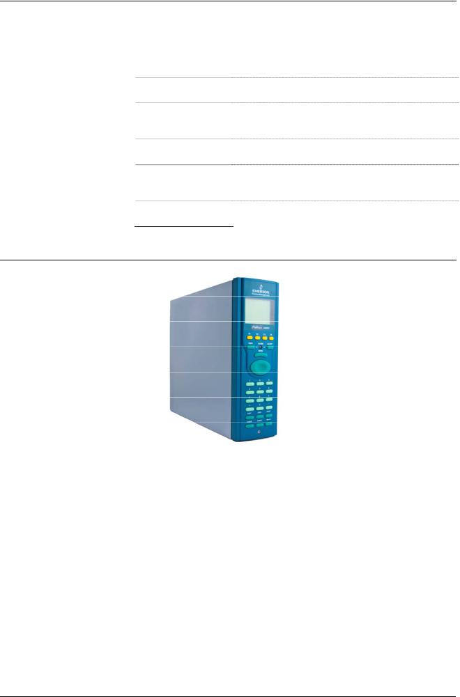
Figure 1-1. The FloBoss S600+ Flow Computer
The FloBoss S600+ Flow Computer is a panel-mount flow computer designed specifically to measure hydrocarbon liquid and gas where versatility and accuracy matter. The standard features of the S600+ make it ideal for fiscal measurement, custody transfer, batch loading, and meter proving applications. The S600+ allows you to configure multi-stream, multi-station applications, enabling you to simultaneously meter liquids and gasses.
The S600+ is designed for use either as a stand-alone flow computer or as a system component. The intelligent I/O modules fit both gas and liquid applications and typically support two dual-pulsed streams and a header. Adding I/O modules (up to a maximum of three) allows you to configure up to six dual-pulsed streams or up to 10 single-pulsed streams and two headers. The S600+ supports orifice, ultrasonic, turbine, positive displacement, Coriolis, Annubar, and V-Cone® flow
1-2 |
General Information |
Revised Mar-11 |

S600+ Instruction Manual
meter types and master meter, small volume compact, and pipe (both bi-directional and uni-directional) proving methods.
The S600+ offers a variety of communication interfaces:
Two LAN ports (on the enhanced CPU module) for Ethernet 10Base-T or 100Base-T full-duplex connectivity (using either Modbus TCP or Modbus over Ethernet protocols).
Note: The Ethernet module (P190), which provided an additional Ethernet port for previous versions of the S600, is not compatible with the S600+.
HART® communication using up to two 12-channel HART modules, each of which supports point-to-point and multi-drop architectures for up to 50 transmitters.
An embedded webserver allows remote access to the flow computer. Security is provided using user name and password
protection with a detailed event log for audit purposes (supports Windows® Internet Explorer® Version 5 or greater).
Two configurable EIA-232 (RS-232) serial ports.
Three EIA-422/485 (RS-422/RS-485) serial ports (supporting up to 57,600 bps baud) and up to four EIA-485 (RS-485) 2-wire serial ports (supporting up to 57,600 baud rate) for connection to intelligent meters, Modbus SCADA data networks, DCS supervisory systems, and so on.
One dedicated configuration port (located on the bottom of front display panel) for connection to the Config600 configuration software.
Additional communications interfaces include:
•Serial Q.Sonic®
•Serial printer
•Serial or Modbus TCP Daniel chromatograph via Modbus
•Serial peer-to-peer
•Modbus EFM protocol, Modbus RTU, Modbus ASCII, Modbus over Ethernet, and Modbus TCP
Miscellaneous interfaces which can operate via serial or Modbus TCP:
Daniel liquid ultrasonicDaniel gas ultrasonic
Sick ultrasonic
Daniel chromatograph
Note: All ports can connect to DCS systems, ultrasonic meters, Coriolis meters, and so on.
Revised Mar-11 |
General Information |
1-3 |

S600+ Instruction Manual
The S600+ uses distributed processing to achieve maximum performance. The CPU module incorporates a hardware floating point processor. Each additional module also has local processing to convert inputs and output from engineering units to field values and vice-versa, as well as running background tests and PID loops.
The firmware uses 64-bit (double) precision floating point numbers for the highest accuracy when performing all metering calculations. Cumulative totals are stored in three separate memory locations (Trireg format) for maximum integrity. The user language LogiCalc™ also allows you to perform logical control and double-precision mathematical functions on the database objects.
Figure 1-2. CPU Module
Figure 1-3. Intelligent I/O Module
Front Display The S600+’s front panel interface enables you to manage an existing Panel configuration or create a configuration using the PC-based Config600
configuration software.
1-4 |
General Information |
Revised Mar-11 |
S600+ Instruction Manual
A communications port on the bottom of the panel provides a way to directly connect to a PC. The front panel interface consists of a backlit LCD display, a 29-button keypad, and an alarm status LED (see Figure 1-4).
Figure 1-4. Front Display Panel
1.3Config600™ Configuration Software
Using Config600, you can both send (upload) new or modified configurations to the S600+ and receive (download) existing configurations from the S600+. You can also define the following functions:
Stream and station totalisation.
Batch totalisation and correction.
Three-term PID control.
Flow balancing.
Flow scheduling.
Automatic proving sequence.
K-factor or meter factor linearisation.
Valve monitor/control.
Sampler control.
Station densitometer.
Station gas chromatograph.
Forward, reverse, and premium error totals.
Comprehensive maintenance mode.
Revised Mar-11 |
General Information |
1-5 |

S600+ Instruction Manual
Reporting.
Modbus.
Modify display matrix.
Config600 is a suite of software editors that enables you to monitor, configure, and calibrate the S600+. The software comes in three versions – Config600 Lite, Config600 Lite+, and Config600 Pro – with Config600 Pro being the most powerful version.
Note: The S600+ does not operate until you send a configuration to it from the host PC.
IPL600 Remote Automation Solutions provides a separate utility program called “Interactive Program Loader 600” (or “IPL600”).
Using IPL600 and an IP or a dedicated serial port connection between a host PC and an S600+, you can transfer and receive configuration files (reports, Modbus configuations, customised displays, and LogiCalc programs). While included as the Config Transfer utility in Config600, IPL 600 has a standalone use for situations when you do not need the full functionality of Config600. Details on using Config Transfer/IPL600 are provided in the Config600 Software Configuration User Manual (A6169).
1.3.1 Config600 Lite
Use the Config600 Lite software editor suite to modify pre-developed configurations, transfer existing configurations, edit items on the front panel display, and customise reports.
Note: You typically use Config600 Lite to custom-configure a new
S600+ during installation.
With Config600 Lite you can:
Edit process configuration data, including orifice size, analog input scaling, alarm limits, and keypad values.
Build and customise Modbus slave maps, Modbus master polling sequences, front panel displays, and period report formats.
Customise the alarm system, including alarm groups, suppression, and inhibits.
Configure system security by setting user names and passwords, and assigning access levels for each data object on the displays.
Specify the engineering units and totalisation rollover value.
Reflash the CPU module firmware with software upgrades and transfer configurations via the Config Transfer utility (IPL600).
1.3.2Config600 Lite+
The Config600 Lite+ software editor suite provides all the functionality of the Config600 Lite suite, but adds the ability to create a configuration file.
1-6 |
General Information |
Revised Mar-11 |

S600+ Instruction Manual
With Config600 Lite+ you can:
Create a new application from base templates for gas, liquid, and prover applications.
Edit process configuration data, including orifice size, analog input scaling, alarm limits, and keypad values.
Build and customise Modbus slave maps, Modbus master polling sequences, front panel displays, and period report formats.
Customise the alarm system, including alarm groups, suppression, and inhibits.
Configure system security by setting user names and passwords, and assigning access levels for each data object on the displays.
Specify the engineering units and totalisation rollover value.
Reflash the CPU module firmware with software upgrades and transfer configurations via the Config Transfer utility (IPL600).
1.3.3Config600 Pro
Use the Config600 Pro software editor suite to create new configurations, modify existing configurations, transfer existing configurations, edit items on the front panel display, and edit custom reports.
With Config600 Pro you can:
Create a new application from base templates for gas, liquid, and prover applications.
Edit process configuration data, including orifice size, analog input scaling, alarm limits, and keypad values.
Build and customise Modbus slave maps, Modbus master polling sequences, front panel displays, and period report formats.
Specify the engineering units and totalisation rollover value.
Customise the alarm system, including alarm groups, suppression, text, and inhibits.
Configure system security by setting user names and passwords, and assigning access levels for each data object.
Add and remove objects from the database.
Program special features using LogiCalc.
Reflash the CPU module firmware with software upgrades and transfer configurations via the Config Transfer utility (IPL600).
Note: To obtain a Config600 Pro licence you must first attend and successfully complete a training course.
Revised Mar-11 |
General Information |
1-7 |

S600+ Instruction Manual
1.4Additional Technical Information
Refer to the following technical documents (available at www.EmersonProcess.com/Remote) for additional and most-current information.
Table 1-1. Related Technical Information
Name |
Form Number |
Part Number |
FloBoss™ S600+ Flow Computer |
S600 |
D301151X412 |
Config600™ Configuration Software |
Config600 |
D301164X012 |
Config600™ Configuration Software User Manual |
A6169 |
D301220X412 |
1.4.1 Open Source Software
The FloBoss S600+ contains open source software covered by the GPL, GPL2, GPL3, LGPL, OpenSSL, SSLeay, zlib, libzip2, and Apache open source software licenses. The specific software being used is U-Boot, the Linux kernel, glibc, Apache web server, mod_sll, mod_alias, mod_rewrite, OpenSSL, BusyBox, ntpclient, tar32, and JFFS2. These licenses are contained on the S600+ Open Source Software CD (part number S600SRCOPEN). Source code is available upon request. You may obtain a copy of this source code by contacting Remote Automation Solutions Technical Support via SupportNet. This product includes software developed by the OpenSSL Project for use in the OpenSSL Toolkit (http://www.openssl.org). This product includes cryptographic software written by Eric Young (eay@cryptsoft.com).
1-8 |
General Information |
Revised Mar-11 |

S600+ Instruction Manual
Chapter 2 – Installation
This chapter provides instructions on installing the S600+, including installation preparation, procedures for panel-mounting, the installation and removal of plug-in modules, and electromagnetic compatibility (EMC) considerations.
In This Chapter
2.1 |
Preparing for Installation....................................................................... |
2-1 |
||
2.2 |
Environmental Considerations.............................................................. |
2-2 |
||
2.3 |
Required Tools for Installation.............................................................. |
2-2 |
||
2.4 |
Installing the S600+ .............................................................................. |
2-3 |
||
|
2.4.1 |
Unpacking the S600+............................................................. |
2-3 |
|
|
2.4.2 |
Removing the Front Panel ..................................................... |
2-3 |
|
|
2.4.3 |
Installing the Panel-Mounted Unit.......................................... |
2-6 |
|
|
2.4.4 |
Reinstalling the Front Panel................................................... |
2-8 |
|
2.5 |
Installing and Removing Modules......................................................... |
2-8 |
||
2.6 |
Installing EMC Protection ................................................................... |
2-10 |
||
|
|
|
|
|
Failure to exercise proper electrostatic discharge precautions (such as Caution wearing a grounded wrist strap) when accessing the back of the unit or
when handling CPU or I/O modules may reset the processor or damage electronic components, resulting in interrupted operations.
2.1Preparing for Installation
The S600+ installation must conform to all applicable local codes and regulations. All installation procedures should be in accordance with normal practices of good workmanship. Although the S600+ shipped to you may not include all of the hardware options described in this manual, the procedure for the basic installation of the unit remains the same.
Note: We strongly recommend you familiarize yourself with the procedures described in this chapter before you begin to install the S600+.
The S600+ uses a modular design that provides maximum flexibility and ease of installation. The basic panel-mounted version consists of three major components:
Fabricated metal case, complete with pre-installed PSU/backplane and four card slots for the modules (a dedicated CPU slot and three I/O slots).
Removable front panel comprising the LCD display and keypad assembly.
Plug-in modules. A CPU module and one I/O module are supplied for a basic configuration; two blank plates are supplied to cover the unused slots.
Figure 2-1 shows the S600+ system components.
Revised Mar-11 |
Installation |
2-1 |

S600+ Instruction Manual
Figure 2-1. FloBoss S600+ System Components
Note: User-supplied tools to assist in the installation process may include a Phillips screwdriver, a regular screwdriver, a small adjustable spanner wrench, and a 2.5mm Allen key.
2.2Environmental Considerations
The S600+ panel mounted flow computer is designed for use within the control room. Place it in a position that provides ease of use, comfort, and safety for operators and maintenance personnel. The optimum height for viewing and using the display and keypad is at operator eye level.
If you install one or more units in a confined space with other heat- Caution producing equipment, give special attention to the combined heating
effect. This combined heat could increase the environmental temperature beyond its acceptable threshold, thereby impacting performance.
2.3Required Tools for Installation
Before you attempt to install the S600+, ensure that you have the following tools:
Small flat-blade screwdriver suitable for the slot-headed captive screws on the rear of the case that secure each plug-in board into the case.
5.5 mm (5 BA) hex or small adjustable wrench for the front panel bosses.
2-2 |
Installation |
Revised Mar-11 |

S600+ Instruction Manual
2.5 mm Allen key suitable for the hex cap screw on the front face of the front panel that secures the front panel molding to the case.
2.4Installing the S600+
Refer to the following procedures for installing the various S600+ components, including the front panel, panel-mounted unit, and modules.
2.4.1 Unpacking the S600+
Unpack the S600+ carefully and inspect parts for visual damage.
Note: Do not discard packaging material until after you have identified all pieces of the shipment and you are confident that all parts are working correctly.
2.4.2 Removing the Front Panel
To begin the mounting process, remove the front panel from the S600+:
1.Ensure power has been removed from the S600+.
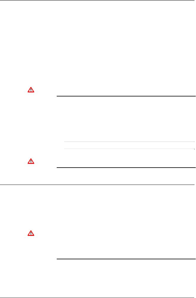
2.Using a 2.5 mm Allen key, remove the hex cap screw from the bottom centre of the front panel (refer to Figure 2-2).
Figure 2-2. Removing the Front Panel
Note: A security cap may cover the hex cap screw.
3.Carefully slide the front panel up 4 mm (0.15 in) to allow it to clear the retaining groove at the top of the case, and then allow the panel to come forward to clear the panel case completely (refer to Figure 2-3).
Revised Mar-11 |
Installation |
2-3 |

S600+ Instruction Manual
Figure 2-3. Lifted Front Panel
4.Disconnect the ribbon cable from the back of the front panel at the blue connector (refer to Figure 2-4). Observe the orientation of the connector with its mating keyway. You must correctly re-insert the ribbon cable at the end of the installation process.
Do not remove the ribbon cable from the S600+ housing. This might Caution damage the S600+. Also, the ribbon cable may also have an EMC
clamp. Be sure to leave it intact without damaging the ribbon cable.
2-4 |
Installation |
Revised Mar-11 |

S600+ Instruction Manual
Disconnect
 Here
Here
|
Figure 2-4. Remove Connector |
|
5. Remove the top and bottom bosses from the unit housing, using a |
|
5.5 mm (5 BA) hex wrench. |
|
Table 2-1. Mounting Dimensions |
Part |
Dimensions |
Display Keypad Molding |
85 mm (3.35") width x 269 mm (10.59") height x 28 mm (1.10") deep |
Case |
84.5 mm (3.327") width x 270 mm (10.63") height x 303.8 mm (11.94") |
|
deep |
Panel Cutout |
66 mm (2.6") width x 150 mm (5.9") height |
Pitch Between Cases |
110 mm (4.33") giving 25 mm (0.98") air gap |
Max Panel Thickness |
10 mm (0.39") |
Access |
Allow 300 mm (11.81") clearance directly behind case for maintenance |
Revised Mar-11 |
Installation |
2-5 |

S600+ Instruction Manual
Figure 2-5. Panel Mount Dimensions
2.4.3 Installing the Panel-Mounted Unit
After removing the front panel, install the panel-mounted unit:
1.Keeping environmental considerations in mind, construct the framework of the cubicle to support the operating panel.
Note: A standard 483 mm (19 in) rack that is 311 mm (12.25 in) high can accommodate up to four S600+s provided you support the rear of the case.
2.Refer to Figure 2-6 and Table 2-1 for position details for two 7 mm (0.276 in) holes and a cutout. The panel cutout should be rectangular for each S600+. Allow a tolerance of ± 3 mm (0.12 in) on each axis.
2-6 |
Installation |
Revised Mar-11 |
S600+ Instruction Manual
Figure 2-6. Panel Cutout Dimensions
Note: The S600+ fits into existing S500 and 869 flow computer panel cutouts.
3.Ensure a panel thickness of at least 3 mm (0.12 in) to prevent distortion. If you use a thinner panel, support the rear of the case (refer to Figure 2-7).
Caution |
Always use a rear support or anchor to prevent twisting and other |
distortion effects during installation and maintenance. |
Figure 2-7. Panel Mount Support
Revised Mar-11 |
Installation |
2-7 |
S600+ Instruction Manual
4.Place the front of the case against the rear of the prepared cutout.
5.Re-install the top and bottom bosses and tighten with a 5.5 mm (5 BA) hex wrench.
6.Once you have fitted the rear support, use a self-tapping screw to secure the case to the rear support. The maximum depth of the screw inside the case should be 3 mm (0.12 in).
2.4.4Reinstalling the Front Panel
Re-installing the front panel is the final stage of the installation process:
|
1. |
Connect the ribbon cable to the front panel. |
|
|
|
Caution |
Note how the connector fits into the keyway. You must insert the |
|
ribbon cable correctly. Do not force the connector into the keyway. |
||
|
2. |
Place the top of the front panel over the retaining groove on the top |
|
|
boss and slide the front panel downwards. |
|
3. |
Secure the front panel by placing the hex cap screw into its recess |
|
|
in the bottom centre of the front panel. |
|
4. |
Using a 2.5 mm Allen key, tighten the screw finger-tight. Turn an |
|
|
additional 180 degrees clockwise to complete the installation. |
|
|
Note: Replace the security cap if one was originally fitted. |
|
|
|
Caution |
Do not over-tighten the screw. Over-tightening will damage the panel |
|
face. |
||
2.5Installing and Removing Modules
|
The S600+ ships with the CPU and I/O modules already installed. |
|
Follow this procedure if you need to remove the modules for |
|
maintenance or upgrade purposes. |
|
The CPU module is located in the left-most rear slot of the case. You |
|
can insert I/O modules in the remaining slots or leave them empty. |
|
Cover any empty slots with the blank cover plates. |
|
|
Caution |
Take suitable electrostatic discharge precautions before you remove |
any of the modules. |
|
|
The terminals on some modules may be wired to electrical potentials |
|
sufficiently high to cause electrical shock and injury. Turn off and |
|
discharge any power sources for connected devices before you |
|
perform any installation or repair work. |
Removal To remove a module:
1.Power down the S600+ before you attempt to extract a module.
2.Unscrew the retention screws before you attempt to remove a module. This avoids damage to the ejectors (refer to Figure 2-8).
2-8 |
Installation |
Revised Mar-11 |
S600+ Instruction Manual
Ejectors
Figure 2-8. Unscrewing the Retention Screws
3.Unlatch the ejectors for the appropriate module and pull the module clear of the case. You may need to rock the module slightly to release it from its connectors (refer to Figures 2-9 and 2-10).
Figure 2-9. Using the Ejectors
Revised Mar-11 |
Installation |
2-9 |

S600+ Instruction Manual
Figure 2-10. Module Ready for Removal or Insertion
Installation To install a module:
1.Carefully align the module with the guides (located at the top and bottom of the case). Gently slide the module into the case until it seats fully with the appropriate connector on the backplane.
2.Press each of the two ejectors securely into place once the module is fully inserted.
Inserting and seating a module along the guides does not require Caution excessive force. Take care not to twist or otherwise distort the module
during the installation.
3.Secure the module with the retention screws (two per board).
2.6Installing EMC Protection
Your site may require you to install electromagnetic compatibility (EMC) shielding on the S600+ to minimize electromagnetic interference. The S600+ EMC protection kit (which came with your S600+) typically has the following components:
1 security backplate (place over the installed modules)
1 25-way EMISTOP Inline T Filter Adaptor (attach to the 25-pin socket A on the I/O module)
1 37-way EMISTOP Inline T Filter Adaptor (attach to the 37-pin socket B on the I/O module)
3 large (for 13mm cable) ferrite clamps
3 medium (for 10mm cables) ferrite clamps
1 small (for 6.5mm cables) ferrite clamp
2-10 |
Installation |
Revised Mar-11 |

S600+ Instruction Manual
2 M3 x 6mm screws (which secure the EMC backplate to the sides of the S600+ housing)
5 TY523 Ty-Rap self-locking cable fasteners (use as necessary to secure cables)
Note: These are standard components for a standard configuration. If your S600+ has a different configuration (for example, additional modules), you may have more components.
Install the EMC kit after you install the S600+ but before you wire the modules.
To install the EMC components:
1.Unscrew and remove the small Phillips-head screws on the I/O module (see Figure 2-11).
Remove screws
Figure 2-11. Screws on I/O Module
2.Place the security backplate over the modules already installed in the S600+ and secure the backplate to the I/O module using the two screws you removed in step 1 (see Figure 2-12).
Revised Mar-11 |
Installation |
2-11 |

S600+ Instruction Manual
Figure 2-12. Security Backplate in Place
Note: In actual operation, the two right-most slots on the S600+ shown in Figure 2-12 would either contain modules or would be covered by blanking plates.
3.Secure the backplate to the sides of the S600+ housing using the 2 M3 x 6mm screws.
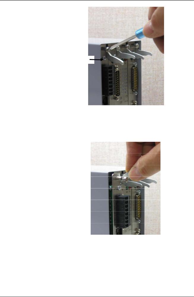
4.Place and secure the 25-way and 37-way EMISTOP adaptors (see Figure 2-13) onto, respectively, sockets A and B on the I/O module (see Figure 2-14).
Figure 2-13. EMISTOP Connector
5.Wire the modules according to your site’s requirements.
6.Attach a small ferrite clamp onto the wiring to socket A on the I/O module. Attach large ferrite clamps onto the cables to sockets B and C (see Figure 2-14).
2-12 |
Installation |
Revised Mar-11 |
S600+ Instruction Manual
Medium ferrite clamp
25-way EMISTOP
37-way EMISTOP
Large ferrite clamps
Figure 2-14. Clamps on I/O Module Wiring
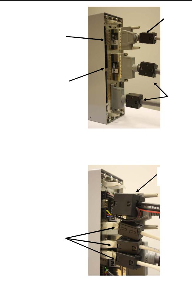
7.Attach a large ferrite clamp onto the wiring to the CPU’s power connections and one medium clamp to the COM3 and COM 4 connections (see Figure 2-15).
Large ferrite clamp
Medium ferrite clamps
Figure 2-15. Clamps on CPU Module Power & COM Connections
Revised Mar-11 |
Installation |
2-13 |

S600+ Instruction Manual
8.Attach a medium ferrite clamp onto the wiring for COMs 5, 6, and 7 and a small ferrite clamp onto the Ethernet cable (see Figure 2- 16).
Small ferrite clamp
Medium ferrite clamp
Figure 2-16. Clamps on CPU Module COM and Ethernet Connections
This completes the installation process and provides the S600+ with
EMC protection.
2-14 |
Installation |
Revised Mar-11 |

S600+ Instruction Manual
Chapter 3 – CPU Module
This chapter provides information on the power and communication connections for the CPU module.
In This Chapter
3.1 |
CPU Module (P152)............................................................................ |
3-1 |
|
3.2 |
Power Supply...................................................................................... |
3-4 |
|
|
3.2.1 |
Watchdog Relay .................................................................... |
3-4 |
|
3.2.2 |
On-Board Battery Backup...................................................... |
3-4 |
3.3 |
Communication Ports ......................................................................... |
3-5 |
|
|
3.3.1 EIA-232 (RS-232) Serial Port ................................................ |
3-6 |
|
|
3.3.2 EIA-422 (RS-422)/EIA-485 (RS-485) Multi-drop Port............ |
3-7 |
|
|
3.3.3 |
Ethernet LAN Ports................................................................ |
3-7 |
|
3.3.4 Local Operator PC or Remote Display Port .......................... |
3-7 |
|
3.4 |
CPU Connectors and Jumpers........................................................... |
3-8 |
|
3.5 |
USB Port............................................................................................. |
3-9 |
|
3.6 |
Additional Technical Information ........................................................ |
3-9 |
|
|
|
|
|
Failure to exercise proper electrostatic discharge precautions (such as Caution wearing a grounded wrist strap) when accessing the back of the unit or
when handling CPU or I/O modules may reset the processor or damage electronic components, resulting in interrupted operations.
3.1CPU Module (P152)
The CPU module contains the host processor and associated peripherals, which form the heart of the S600+ system. Various plug-in connections are provided on the rear backplate of the CPU module. Refer to Figure 3-1 for an illustration of the CPU module backplate and to Figure 3-2 for a schematic of the CPU power terminations. Figure 3-3 shows the wiring terminations. Additionally, the module uses connectors and jumpers, which are set at the factory prior to shipping. See Section 3.5, Jumpers for further information.
It is recommended that all wiring be made with stranded wire that is no larger than 1.5 mm2 (0.0023 in2) For the communication ports, wiring of 1.75 mm2 to 1.65 mm2 (0.0027 in2 to 0.0025 in2) is recommended. Power wiring is recommended to be 1.5 mm2 (0.0023 in2). Observe all local wiring practices and regulations.
Do not use a Mega or similar instrument to check for isolation or Caution continuity between signals on any of the S600+ connectors. These
instruments produce voltages far in excess of design parameters and may damage the S600+ or its connectors.
Revised Mar-11 |
CPU Module |
3-1 |

S600+ Instruction Manual
TB-1 Power
First Ethernet port
COM 4
COM 5
COM 6
COM 7
Four additional RS-485 ports (COM 9 through COM 12)
 Second Ethernet port
 COM 3
COM 3
Note: You can configure the A (–) terminal of COM 12 as a digital input
USB port
Figure 3-1. CPU Module Backplate
Ejector
latches Backup battery
Figure 3-2. CPU Module
3-2 |
CPU Module |
Revised Mar-11 |
Loading...