


 Loading...
MARINE
CONTROL UNITS
Elite Control Series
EN Elite Control
Installation and Operating Manual. . . . .2
WARNING |
|
Cancer and Reproductive Harm |
|
www.P65Warnings.ca.gov |
L-5507 | Form No. 341204 20200325 | ©2020 Dometic Corporation |
|

Contents |
Elite Control |
Service Center & Dealer Locations
Visit: www.dometic.com
Read these instructions carefully. These instructions MUST stay with this product.
Contents
1 Explanation of Symbols and Safety Instructions . . . . . . . . . . . . . . . . . . . . . . . . . . . . . 2
1.1 Recognize Safety Information. . . . . . . 2 1.2 Understand Signal Words. . . . . . . . . 2 1.3 Supplemental Directives. . . . . . . . . 3
1.4General Safety Messages. . . . . . . . . 3
2 Intended Use. . . . . . . . . . . . . . . . . . . . . . . . . . . . 3
3 General Information. . . . . . . . . . . . . . . . . . . . . . 3
3.1Tools and Materials. . . . . . . . . . . 3
3.2 Display Features . . . . . . . . . . . . 4
4 Specifications . . . . . . . . . . . . . . . . . . . . . . . . . . . 4
4.1Product Dimensions . . . . . . . . . . . 4
4.2 Cable Length. . . . . . . . . . . . . . 5
4.3Available System Inputs . . . . . . . . . 5
4.4 Operational Specifications. . . . . . . . 5
5 |
Wiring Diagrams. . . . . . . . . . . . . . . . . . . . . . |
. . . 6 |
|
6 |
Installation.. . . . . . . . . . . . . . . . . . . . . . . . . . . . . |
8 |
|
|
6.1 |
Choosing a Display Panel Location. . . . . |
. . . . 8 |
|
6.2 |
Preparing the Wall. . . . . . . . . |
. . . 8 |
6.3Installing an Optional Sensor . . . . . . . 8
6.4Mounting the Display Panel . . . . . . . . 9
6.5 Testing the Display . . . . . . . . . . . 9
7 Operation. . . . . . . . . . . . . . . . . . . . . . . . . . . . . . |
9 |
7.1Understanding the Heating and Cooling Cycles . . . . . . . . . . . . . . . . 10
7.2Choosing the Control Operation. . . . . 11
7.3Using the Control Display Panel. . . . . . 13
7.4 Programming the Control. . . . . . . . 14 7.5 Navigation Tree. . . . . . . . . . . . 24
8Troubleshooting . . . . . . . . . . . . . . . . . . . . . . . . 25
9Disposal. . . . . . . . . . . . . . . . . . . . . . . . . . . . . . . 30
10 Warranty Information.. . . . . . . . . . . . . . . . . . . |
30 |
1 Explanation of Symbols and
Safety Instructions
This manual has safety information and instructions to help you eliminate or reduce the risk of accidents and injuries.
1..1 Recognize Safety Information
This is the safety alert symbol.. It is used to alert you to potential physical injury hazards. Obey all safety messages that follow this symbol to avoid possible injury or death.
1..2 Understand Signal Words
A signal word will identify safety messages and property damage messages, and also will indicate the degree or level of hazard seriousness.
DANGER!
Indicates a hazardous situation that, if not avoided, will result in death or serious injury.
WARNING
Indicates a hazardous situation that, if not avoided, could result in death or serious injury.
CAUTION
Indicates a hazardous situation that, if not avoided, could result in minor or moderate injury.
NOTICE: Used to address practices not related to physical injury.
IIIndicates additional information that is not related to physical injury.
2 |
EN |
|
|

Elite Control |
Intended Use |
|
|
1..3 Supplemental Directives
To reduce the risk of accidents and injuries, please observe the following directives before proceeding to install or operate this appliance:
•Read and follow all safety information and instructions.
•Read and understand these instructions before installing and operating this product.
•The installation must comply with all applicable local or national codes, including the latest edition of the following standards:
––ANSI/NFPA70, National Electrical Code (NEC)
––American Boat and Yacht Council (ABYC)
1..4 General Safety Messages
WARNING: ELECTRICAL SHOCK, FIRE, AND/
OR EXPLOSION HAZARD.. Failure to obey the following warnings could result in death or serious injury:
•Use only Dometic replacement parts and components that are specifically approved for use with the appliance.
•Avoid improper installation, adjustment, alteration, service, or maintenance of the appliance. Service and maintenance must be done by a qualified service person only.
•Do not modify this product in any way. Modification can be extremely hazardous.
•This product should be installed in a controlled, indoor environment.
2 Intended Use
The Elite Control is a user-friendly 5-volt logic and micro controller-based unit designed for use with direct expansion (DX), reverse-cycle air-conditioning systems, and chilled-water systems (CW). The 5 button display panel has 33 programmable parameters, automatic and manual fan speeds, standard and optional sensor inputs, and fits both Vimar® Idea and Eikon switch bezels.
This manual provides all necessary information for the proper installation and operation of the Elite Control display panel. Poor installation and misunderstood operating parameters will result in unsatisfactory performance and possible failure. The manufacturer accepts no liability for damage in the following cases:
•Faulty assembly or connection
•Damage to the product resulting from mechanical influences and excess voltage
•Alterations to the product without express permission from the manufacturer
•Use for purposes other than those described in the operating manual
Dometic Corporation reserves the right to modify appearances and specifications without notice.
3 General Information
This section provides information on the tooling, parts, and display features for the Elite Control.
IIThe images used in this document are for reference purposes only. Components and component locations may vary according to specific product models. Measurements may vary ±0.38 in. (10 mm).
The Elite Control models have the same features, installation procedure, and functionality.
3..1 Tools and Materials
Dometic recommends that the following tools and materials be used while installing the appliance:
Recommended Tools
Phillips-head Screwdriver |
Saw |
|
|
|
|
Safety Glasses |
|
|
|
|
|
Included Parts |
|
Quantity |
|
||
|
|
|
Screws |
|
4 |
Elite Control |
|
1 |
|
|
|
EN |
3 |
|
|
Specifications |
Elite Control |
Additional Parts1 |
DX |
CW |
Required for CW Installations (not included) |
|
|
|
|
|
Water Inlet Temperature Sensor |
|
X |
|
|
|
Optional Parts |
|
|
|
|
|
Outside Air Temperature (OAT) Sensor |
X |
X |
|
|
|
Inside Air Temperature Sensor |
X |
X |
|
|
|
Auxiliary Electric Heater2 |
X |
X |
Room Temperature/Relative Humidity |
X |
X |
Combination Sensor2 |
|
|
Seawater Low-Limit Temperature Sensor2 |
X |
|
Pump Sentry Water Sensor |
X |
|
|
|
|
1Additional parts are not included with the standard control package.
2Available in software revision C39 and newer.
IIThe maximum length for the display and sensor cables is 75 ft (22.9 m).
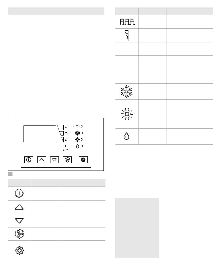
3..2 Display Features
This section explains the function of the buttons and indicators on the Elite Control display.
Indicator |
Indicator Name |
Function |
|
|
Temperature LED |
Displays the inside, set |
|
|
point, outside, and water |
||
|
Display |
||
|
temperatures |
||
|
|
||
|
Fan Speed |
Indicates the fan speed as |
|
|
high, medium, or low |
||
|
|
||
AUTO |
Automatic Fan |
Located below the fan speed |
|
indicator, the LED illuminates |
|||
Mode |
|||
|
when active |
||
|
|
||
|
|
Located above the COOL |
|
|
|
mode indicator, the LED |
|
AUTO |
Automatic Mode |
illuminates when active. |
|
• The COOL or HEAT mode |
|||
|
|
LED also lluminates to |
|
|
|
indicate which cycle is |
|
|
|
active |
|
|
|
When only this indicator is lit, it |
|
|
Cool Mode |
indicates the COOL-only mode |
|
|
|
is active |
|
|
|
• When only this indicator is |
|
|
|
lit, it indicates the HEAT- |
|
|
|
only mode is active |
|
|
Heat Mode |
• When the indicator is |
|
|
|
flashing, indicates the |
|
|
|
AUXILIARY HEAT mode is |
|
|
|
active1 |
|
|
Dehumidification |
Indicates DEHUMIDIFICATION |
|
|
Mode |
mode is active |
1 If parameter P-13 for the auxiliary heat is enabled, it can also be selected and the display will show A-H.
1 Elite Control Display |
|
|
Button |
Button Name |
Function |
|
Power |
Toggles between ON and OFF |
|
mode |
|
|
|
|
|
Up |
Raises the temperature set |
|
point by 1 °F (0.6 °C) |
|
|
|
|
|
Down |
Lowers the temperature set |
|
point by 1 °F (0.6 °C) |
|
|
|
|
|
Fan |
Cycles through the different |
|
fan speeds |
|
|
|
|
|
|
Selects one of the |
|
|
four operating modes |
|
Mode |
(AUTOMATIC, COOL, HEAT, |
|
|
or DEHUMIDIFICATION) when |
|
|
the system is in the ON mode |
4 Specifications
The following table lists the Elite Control dimensions, cables, system inputs, and operational specifications.
4..1 Product Dimensions
Display Panel Dimensions |
4.4 in. x 3.0 in. |
for the Idea Bezel |
(112 mm x 76 mm) |
|
|
Display Panel Dimensions |
4.5 in. x 2.9 in. |
for the Eikon Bezel |
(114 mm x 74 mm) |
|
|
Cut-Out Dimensions for |
2.3 in. x 3.5 in. |
the Idea Bezel |
(58 mm x 89 mm) |
|
|
Cut-Out Dimensions for |
1.9 in. x 2.8 in. |
the Eikon Bezel |
(48 mm x 71 mm) |
|
|
4 |
EN |
|
|

Elite Control |
Specifications |
|
|
4..2 Cable Length
Display Cable |
15.0 ft (4.6 m) Standard |
|
Self Contained |
||
|
||
|
|
|
Inside Air Temperature |
7.0 ft (2.1 m) Standard |
|
Sensor (optional) |
||
|
||
|
|
|
OAT Sensor (optional) |
15.0 ft (4.6 m) Standard |
|
|
|
|
All custom cable lengths |
|
|
are supplied in standard |
75.0 ft (22.9 m) Maximum |
|
5 ft (1..5 m) increments |
|
|
|
|
4..3 Available System Inputs
Water Inlet |
|
|
Temperature Sensor |
1 |
|
(CW Installations Only) |
|
|
|
|
|
High Refrigerant Pressure |
1 |
|
|
|
|
Inside Air Temperature |
1 |
|
Sensor (optional) |
||
|
||
|
|
|
Low Refrigerant Pressure |
1 |
|
(optional) |
||
|
||
|
|
|
OAT Sensor (optional) |
1 |
|
|
|
|
Pump Sentry Water |
|
|
Sensor (optional) |
1 |
|
(DX Installations Only) |
|
|
|
|
|
Room Temperature/ |
|
|
Relative Humidity |
1 |
|
Combination Sensor |
||
|
||
(optional) |
|
|
|
|
4..4 Operational Specifications
Set Point Operating |
65 °F to 85 °F (18 °C to 29 °C ) |
|
Range |
||
|
||
|
|
|
Ambient Temperature |
|
|
Operating Range |
5 °F to 150 °F (-15 °C to 66 °C) |
|
Displayed |
|
|
|
|
|
Sensor Accuracy |
± 2 °F @ 77 °F (±1 °C @ 25 °C) |
|
|
|
|
Low Voltage Limit |
95 VAC |
|
100–120 V |
||
|
||
|
|
|
Low Voltage Limit |
195 VAC |
|
200–240 V |
||
|
||
|
|
|
Low Voltage Processor |
50 VAC |
|
Reset |
||
|
||
|
|
|
Universal Line Voltage |
100–240 VAC |
|
|
|
|
Frequency |
50 Hz or 60 Hz |
|
|
|
|
|
6 A @ 115 VAC |
|
Fan Output |
|
|
6 A @ 230 VAC |
||
|
||
|
|
|
Valve Output |
5 A @ 115/230 VAC |
|
|
|
|
For CW Only: |
|
|
Auxiliary Electric |
|
|
Heater Output |
30 A Maximum |
|
(using compressor |
|
|
output L1 and L2) |
|
|
|
|
|
External Triac |
26 A |
|
|
|
|
External Q-Relay |
30 A Maximum |
|
|
|
|
|
1/4 HP @ 115 VAC |
|
Pump Output |
|
|
1/2 HP @ 230 VAC |
||
|
||
|
|
|
|
1 HP @ 115 VAC |
|
Compressor Output |
|
|
2 HP @ 230 VAC |
||
|
||
|
|
|
Minimum Operating |
0 °F (-18 °C) |
|
Temperature |
||
|
||
|
|
|
Maximum Ambient |
180 °F (82 °C) |
|
Operating Temperature |
||
|
||
|
|
|
Maximum Rh Conditions |
99% Non-condensing |
|
|
|
|
Power Consumption |
< 5 W |
|
|
|
EN |
5 |
|
|

Wiring Diagrams |
Elite Control |
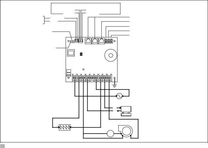
5 Wiring Diagrams
WARNING: ELECTRIC SHOCK HAZARD..
Turn power OFF before performing any electrical installation or maintenance activities. Failure to obey this warning could result in death or serious injury.
Figure 2 and Figure 3 provide examples of the DX and
CW Wiring for the Elite Control.
Display Jacks (for 8- or 6-pin display and cables)
|
|
|
|
|
|
Inside Temperature Sensor Jack |
|
Optional |
0-10 VDC |
|
|
|
Not Active |
|
|
|
|
|
||
|
DC Blower |
GND |
|
|
|
Optional Water-Out Temperature Sensor |
|
|
|
|
|
|
Optional Outside Air Temperature Sensor |
Low-Pressure |
High-Pressure |
|
|
|
|
|
Switch |
Switch |
|
|
|
|
|
JP5 Temperature Sensor Selection Jumper |
|
|
|
|
|
|
JP2 Low Pressure Switch Jumper |
|
|
|
|
|
|
|
Gate Terminals to |
|
|
|
|
|
Auxiliary Heat Relay |
|
|
|
|
|
|
|
|
Comp L1 |
|
|
Ground |
|
|
|
|
|
|
|
|
|
|
Pump L1 |
|
|
L2 |
L1 |
|
|
Pump L2 |
|
|
||
|
|
|
|
|
|
|
|
|
|
|
|
|
AC |
|
|
Comp L2 |
Fan Run |
|
|
|
|
|
Capacitor |
|
Start |
||
Pump or |
|
|
FanL1 |
|
||
|
|
|
Capacitor |
|||
Pump Relay Panel |
|
|
|
|||
|
|
|
|
|||
|
|
|
|
|
|
|
|
|
|
Fan |
L2 |
|
|
Reversing Valve or |
|
|
L1 |
|
|
|
Compressor |
|
|
|
|||
Electric Heat |
|
2 |
1 |
|
||
|
|
|
|
|||
|
|
Run Capacitor |
|
6 |
Start Relay |
|
|
|
|
|
|
||
|
|
|
|
5 |
4 |
|
|
|
|
|
|
||
2 DX Wiring Diagram
6 |
EN |
|
|
Elite Control |
Wiring Diagrams |
|
|
|
|
SMX DISPLAYS ONLY |
|
|
|
|
COM |
COM |
|
|
For Humidistat |
For Changeover Switch |
|
|
Optional |
0-10 VDC |
|
|
Display Jacks (for 8- or 6-pin display and cables) |
|
|
Inside Temperature Sensor Jack |
||
DC Blower |
GND |
|
|
|
|
|
|
|
Required Water Inlet Temperature Sensor |
JP1 System Selection Jumper |
|
|
Optional Water-Out Temperature Sensor |
|
|
|
Optional Outside Air Temperature Sensor |
||
|
|
|
|
|
JP5 Temperature Sensor Selection Jumper |
|
|
|
|
|
|
|
Ground |
|
|
|
|
L2 |
L1 |
|
|
|
AC |
|
|
|
|
L1 |
Water Valve |
|
|
|
L2 |
|
|
|
|
|
|
|
L2 |
L1 |
Fan Run |
|
|
|
|
Capacitor |
Fan |
|
Electric Heat Strip |
|
||
|
L2 |
L1 |
||
|
|
|
||
3 CW Wiring Diagram
EN |
7 |
|
|
Installation |
Elite Control |
6 Installation
WARNING: ELECTRIC SHOCK HAZARD..
Turn power OFF before performing any electrical installation or maintenance activities. Failure to obey this warning could result in death or serious injury.
NOTICE: Failure to obey the following notices could result in damage to the product:
•Do not locate the display panel in direct sunlight, near any heat-producing appliances, or in a bulkhead where temperatures radiating from behind the panel may affect performance.
•Do not mount the display in the supply-air stream or above or below a supply-air or return-air grille.
•Do not mount the display behind a door, in a corner, under a stairwell, or any place where there is no freely circulating air.
•Do not staple sensor cables during installation.
•Do not use a screw gun and do not over-tighten the screws when mounting the display. Either method may damage the display.
IIThe system’s display built-in temperature sensor is located in the control’s display panel. An
optional inside air temperature sensor is required if installing the display panel in a cabinet, enclosed space, or any area where the accurate sensing of the room temperature would be impaired.
This section describes how to install an Elite Control.
6..1 Choosing a Display Panel
Location
Place the display panel in an area that meets the following location criteria:
•Mounted on an inside wall of the cabin, away from direct sunlight
•Sets slightly higher than mid-height of the cabin
•Located in an area of freely circulating air
•Placed a maximum distance of 15 ft (4.6 m) from the air conditioner
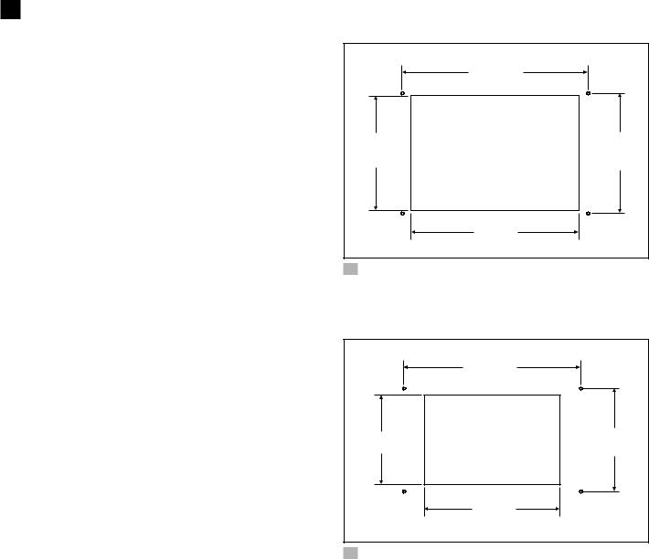
6..2 Preparing the Wall
Cut the cabin wall to fit the display panel, according to the bezel being used.
|
w |
q |
e |
|
r |
4 Idea Bezel Cutout Dimensions
q2.3 in. (58 mm) |
e2.4 in. (61 mm) |
w3.8 in. (97 mm) |
r3.5 in. (89 mm) |
|
w |
q |
e |
|
r |
5 Eikon Bezel Cutout Dimensions
q1.9 in. (48 mm) |
e2.2 in. (56 mm) |
w3.8 in. (97 mm) |
r2.8 in. (71 mm) |
6..3 Installing an Optional Sensor
1.Mount the optional sensor according to the installation instructions included with the sensor.
2.Plug the sensor cable into the appropriate sensor jack on the upper side of the control board. Refer to “Wiring Diagrams” on page 6 for details on the sensor jack locations.
8 |
EN |
|
|
Elite Control |
Operation |
|
|
6..4 Mounting the Display Panel
RES SEL |
|
|
|
DC |
PRESS |
SWT |
MA DISPLAY |
CA DISPLAY |
INSIDE |
H20 |
H20 |
OAT |
|
CW EMBLE |
LPF EMBLE |
HP |
LP |
|
|
|
|
IN |
OUT |
||||
JP3 |
|
|
|
|
|
|
|
|
|
||||
JP5 JP1 |
JP2 |
|
|
|
J1 |
|
J2 |
J3 |
P4 |
P5 |
P6 |
||
|
|
|
|
|
|
|
|
|
|
|
|||
|
|
|
|
|
JP4 |
|
|
|
|
|
|
|
|
|
|
|
|
|
|
|
PSNB |
|
|
|
|
|
|
|
|
|
|
|
|
|
JP6 |
|
|
|
|
|
|
AUX HEAT |
|
|
|
|
|
|
|
|
|
VSNB |
|
|
|
GATE |
|
|
|
|
|
|
|
|
|
JP8 |
|
|
|
|
|
|
|
|
|
|
|
|
|
|
|
|
|
TRM-1 |
|
|
|
|
|
|
|
|
|
|
|
|
|
|
|
|
L2 |
|
COMP |
FAN |
PUMP |
PUMP |
L1 |
COMP |
VALVE |
FAN |
|
|
|
|
|
L2 |
L2 |
L2 |
L1 |
L1 |
L1 |
L1 |
|
||
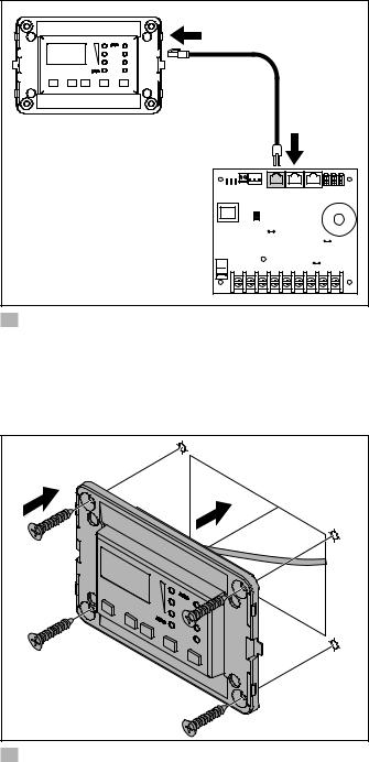
6Plugging in the Display Cable
1.Plug the display cable 8-pin connector into the upper-right jack on the circuit board.
2.Insert the other end of the display cable into the display jack on the back of the display panel.
|
q |
|
e |
r |
w |
7 Securing the Display
qCutout |
eBezel |
wDisplay Panel |
rScrew |
3.Use the four screws provided to secure the display panel to the bulkhead. Do not use a screw gun or overtighten the screws.
4.Snap the bezel onto the display panel frame.
6..5 Testing the Display
NOTICE: For DX units only: do not turn the circuit breaker or power supplied to the unit OFF and then immediately turn it back ON. Allow at least five minutes for the refrigerant pressure to equalize. Failure to obey this notice could result in damage to the air conditioning unit.
1.Open the seawater-intake ball valve (seacock).
2.Turn the display OFF. Wait a minimum of five minutes.
3.Turn the air conditioner circuit breaker ON.
IIIf the seawater pump is on a separate circuit breaker, be sure to turn it ON.
4.Turn the display ON.
5.Press the Fan button.
6.Verify that the fan is running and that a steady airflow is coming out of the supply-air grille.
7.Select a temperature set point lower than the current cabin temperature.
8.Verify that a steady, solid stream of water is coming out from the overboard discharge.
9.Verify that a steady airflow is continues to flow out of the supply-air grille.
IIIf the unit is not functioning as expected, refer to “Troubleshooting” on page 25.
7 Operation
NOTICE: If the unit is cool-only, change parameter P-33 to CL, then select AUTO mode. Do not set the unit to AUTOMATIC mode before changing parameter P-33 to CL. Cool-only units do not heat unless equipped with auxiliary heating. Failure to obey this notice will cause the unit to cool in both modes. Refer to “Selecting a Parameter” on page 16.
IIWhen used with optional auxiliary electric heater, the fan remains ON for four minutes after the heater cycles OFF, even if the fan is set to cycled operation.
IIThe images in this section show the Elite Control display, unless otherwise indicated.
This section describes the cycle, programming, and functions for the Elite Control.
EN |
9 |
|
|

Operation |
Elite Control |
7..1 Understanding the Heating and
Cooling Cycles
The heating and cooling cycles operate differently depending on the system installed. This section describes the possible cycles.
7..1..1 Normal Heating or Cooling Cycle
In AUTOMATIC mode, heating and cooling are supplied as required to meet the cabin temperature set point.
•The system starts a cooling cycle once the cabin temperature exceeds the temperature set point by 2 °F (1 °C) and starts a heating cycle once the cabin temperature falls below the temperature set point by 2 °F (1 °C). The system continues the cycle until the cabin temperature equals the set point.
•During a cycle, the cabin temperature must drop below the set point by at least 4 °F (2 °C) before the system switches from cooling to heating or exceed the set point by at least 4 °F (2 °C) before the system switches from heating to cooling. This behavior prevents small temperature overshoots from causing the system to switch between heating and cooling when it is not necessary.
COOL mode supplies cooling only and HEAT mode supplies heating only.
•The cabin temperature for either mode is maintained within 2 °F (1 °C) of the set point by default.
•When the heating or cooling set point is satisfied, the compressor cycles OFF and the fan returns to low speed.
In Manual Fan Mode, the fan speed remains constant.
7..1..2 Chilled-Water System Operation
(CW Systems Only)
In CW systems, the water valve does not open unless the water temperature is adequate to heat or cool the cabin. The adequate heating or cooling water temperature is defined by the water temperature differential setting in the control parameters. Refer to “Selecting a Parameter” on page 16.
To view the current water temperature, press and hold Power and Down. Refer to “Using the Control Display Panel” on page 13. The fan remains on low speed until the adequate water temperature is available.
IITo provide heat when the required water temperature is not available, install the optional auxiliary electric heater and program parameter P-13. Refer to “Programming the Control” on page 14.
7..1..3 Air and Water Temperature
Differential (CW Systems Only)
The electric heater and the chilled-water heat can affect the CW system.
The optional auxiliary electric heater overlaps with the chilled-water heat by 22 °F (12° C). The heater turns on when required and remains on until the chilled-water temperature exceeds the ambient air temperature by 22 °F (12° C) or until the room temperature is satisfied. During very cold conditions, the auxiliary electric heat overlaps the chilled-water heat to supplement heating.
Water Temperature Differential |
|
Auxiliary |
|
in °F |
Valve |
||
Heater |
|||
Default is 15 °F (-9 °C) |
|
||
|
|
||
|
|
|
|
22 °F (-6 °C) |
Open |
Off |
|
|
|
|
|
15 °F (-9 °C) |
Open |
On |
|
|
|
|
|
7 to 15 °F (-14 to 9 °C) |
Hysteresis |
On |
|
|
|
|
|
7 °F (-14 °C) |
Close |
On |
|
|
|
|
|
7 to 0 °F (-14 to -18 °C) |
Close |
On |
|
|
|
|
|
0 °F (-18 °C) |
Close |
Off |
|
|
|
|
|
0 to -7 °F (-18 to -22 °C) |
Close |
Off |
|
|
|
|
|
-7 °F (-22 °C) |
Close |
Off |
|
|
|
|
|
-7 to -15 °F (-22 to -26 °C) |
Hysteresis |
Off |
|
|
|
|
|
-15 °F (-26 °C) |
Open |
Off |
|
|
|
|
10 |
EN |
|
|
Loading...