


Dometic RM3604, RM3804, RM4804, RM7030, S1521 Service Manual
...This section addresses the most common system problems associated with Refrigerators supplied by The Dometic Corporation. Our intent is to provide you with a guideline of checks to make, should you encounter one of the following symptoms.
Dometic Manual Refrigerators
|
|
|
|
REFER |
|
|
|
|
|
|
|
TO |
PAGE |
|
|
|
SYMPTOM |
CAUSE |
SECTION |
|
|||
|
1. |
No operation. |
Operation |
18C |
37,38 |
|
|
|
|
|
Wiring |
B |
25-30 |
|
|
|
|
|
Switch |
13C,14C |
35 |
|
|
|
2. |
No electric operation. |
Operation |
18C |
37,38 |
|
|
|
|
|
AC Volts |
17C |
36 |
|
|
|
|
|
Heating Element |
10C |
34 |
|
|
|
|
|
Thermostat |
6C |
33 |
|
|
|
|
|
Switch |
13C,14C |
35 |
|
|
|
|
|
Wiring |
B |
25-30 |
|
|
|
3. |
No gas operation — no spark. |
Operation |
18C |
37,38 |
|
|
|
|
|
DC Volts |
15C |
36 |
|
|
|
|
|
Igniter |
12C |
34 |
|
|
|
|
|
Electrode |
12C |
34 |
|
|
|
|
|
High Voltage Cable |
12C |
35 |
|
|
|
|
|
Switch |
13C,14C |
35 |
|
|
|
|
|
Wiring |
B |
25-30 |
|
|
|
4. |
No gas operation — sparks but no flame. |
Operation |
18C |
37,38 |
|
|
|
|
|
LP gas |
1A |
12 |
|
|
|
|
|
Filter |
8C |
33 |
|
|
|
|
|
Orifice |
3A |
14 |
|
|
|
|
|
Burner |
2A |
12 |
|
|
|
|
|
Shut-off Valve |
2A |
12 |
|
|
|
|
|
Safety Valve |
2C |
32 |
|
|
|
|
|
Thermocouple |
3C |
32 |
|
|
|
|
|
Thermocouple Adapter, |
4C |
32 |
|
|
|
|
|
(Top Mount Controls Only) |
|
|
|
|
|
5. |
No cooling on any mode. |
Operation |
18C |
37,38 |
|
|
|
|
|
Level |
1J |
89 |
|
|
|
|
|
Ambient Temperature |
5J |
90 |
|
|
|
|
|
Cooling Unit |
6J |
90 |
|
|
|
6. No cooling on gas — cools properly on other |
LP Gas |
1A |
12 |
|
|
|
|
|
mode(s). (RM2604 & RM2804 ONLY) |
Thermostat |
5C |
33 |
|
|
|
|
|
Filter |
8C |
33 |
|
|
|
|
|
Orifice |
3A |
14 |
|
|
|
|
|
Burner |
2A |
12 |
|
|
|
|
|
Flue Baffle |
3A |
12,13 |
|
|
|
|
|
Flue Tube |
3A |
14 |
|
|
|
7. No cooling on electric — cools properly on other |
AC Volts |
17C |
36 |
|
|
|
|
|
mode(s). (RM2604 & RM2804 ONLY) |
Heating Element |
17C |
37 |
|
|
|
|
|
Thermostat |
9C |
33 |
|
|
|
|
|
Switch |
13C,14C |
35 |
|
|
|
|
|
Wiring |
B |
25-30 |
|
|
|
|
|
|
|
|
|
|
1

|
|
|
|
REFER |
|
|
SYMPTOM |
CAUSE |
TO |
PAGE |
|||
SECTION |
||||||
8. |
Insufficient cooling on all modes. |
Operation |
18C |
37,38 |
||
|
|
|
Level |
1J |
89 |
|
|
|
|
Ventilation |
2J |
89 |
|
|
|
|
Ambient Temperature |
5J |
90 |
|
|
|
|
Air Leaks |
3J |
89 |
|
|
|
|
Thermostat |
6C |
33 |
|
|
|
|
Cooling Unit |
6J |
90 |
|
9. Insufficient cooling on electric — cools prop- |
AC Volts |
17C |
36 |
|||
|
|
erly on other mode(s). |
Heating Elements |
17C |
37 |
|
|
|
|
Thermostat |
6C |
33 |
|
10. |
Insufficient cooling on gas. |
LP Gas Pressure |
1A |
12 |
||
|
|
Cools properly on other mode(s). |
Thermostat |
6C |
33 |
|
|
|
|
Filter |
8C |
33 |
|
|
|
|
Orifice |
3A |
14 |
|
|
|
|
Burner |
2A |
12 |
|
|
|
|
Flue Baffle |
2A,3A |
12,13 |
|
|
|
|
Flue Tube |
3A |
14 |
|
11. |
Freezes on electric – cools properly on other |
Thermostat |
9C |
33 |
||
|
|
mode(s). (RM2604 & RM2804 ONLY) |
Wiring |
B |
25-30 |
|
12. |
Freezes on gas – cools properly on other |
Bypass Screw |
1C |
32 |
||
|
|
mode(s). (RM2604 & RM2804 ONLY) |
Thermostat |
5C |
33 |
|
13. |
|
Won't stay lit on gas. |
LP Gas |
1A |
12 |
|
|
|
|
Safety Valve |
2C |
32 |
|
|
|
|
Thermocouple |
3C |
32 |
|
|
|
|
Thermocouple Adapter, |
4C |
32 |
|
|
|
|
(Top Mount Controls Only) |
|
|
|
|
|
|
Flame Failure Meter |
7C |
33 |
|
|
|
|
(Top Mount Controls Only) |
|
|
|
|
|
|
Flue Baffle |
2A,3A |
12,13 |
|
|
|
|
Flue Cap (Bottom Mount |
3A |
14 |
|
|
|
|
Controls Only) |
|
|
|
|
|
|
Orifice |
3A |
14 |
|
|
|
|
Burner |
2A |
12 |
|
14. |
|
Rapid formation of frost. |
Food Storage |
7J |
90 |
|
|
|
|
Air Leaks |
3J |
89 |
|
|
|
|
Interior Liner Seal to Frame |
9J |
90 |
|
|
|
|
High Humidity |
8J |
90 |
|
15. |
No DC operation – cools properly on AC and |
DC Volts |
15C |
36 |
||
|
|
gas. |
Heating Element |
11C |
34 |
|
|
|
|
Switch |
13C,14C |
35 |
|
|
|
|
Wiring |
B |
25-30 |
|
|
|
|
Relay(RM2610/2810/2604/2804) |
10C |
34 |
|
16. |
Insufficient cooling on DC– cools properly on |
DC Volts |
15C |
36 |
||
|
|
AC and gas. |
Heating Element |
11C |
34 |
|
RM2510/RM2610/RM2810/RM2604/RM2804/ |
Relay (RM2610/2810/2604/2804) |
10C |
34 |
|||
Electrode |
12C |
34 |
||||
RM2552/RM2553 |
||||||
17. |
|
On gas mode, sparks while flame is lit. |
LP Gas |
1A |
12 |
|
|
|
|
Bypass Screw |
1C |
32 |
|
|
|
|
Filter |
8C |
33 |
|
|
|
|
Ignitor |
12C |
34 |
|
2

AES MODELS: RM3604, RM3804, RM4804 and
RM7030 with Product No. 921890201, 921890301
|
|
|
REFER |
|
|
|
|
TO |
PAGE |
SYMPTOM |
CAUSE |
SECTION |
||
1. |
No operation – no panel lights. |
DC Volts |
4F |
65 |
|
|
Fuse |
5F |
71 |
|
|
Wiring |
B |
18,19,21 |
|
|
Upper PC Board |
5F |
67-70 |
|
|
Circuit Board |
5F |
70,71 |
2. |
No operation – has panel lights. |
Thermostat |
5F |
65 |
|
|
Upper Circuit Board |
5F |
67-70 |
|
|
Solenoid |
5F |
65,66 |
|
|
Wiring |
B |
18,19,21 |
|
|
Circuit Board |
5F |
70,71 |
3. |
Operating OK – no panel lights. |
DC Volts |
4F |
65 |
|
|
Wiring |
B |
18,19,21 |
|
|
Upper Circuit Board |
5F |
67-70 |
|
|
Circuit Board |
5F |
70,71 |
4. |
No AC operation – operates on DC and gas. |
AC Volts |
2F |
65 |
|
|
Heating Element |
3F |
65 |
|
|
Upper Circuit Board |
5F |
67-70 |
|
|
Wiring |
B |
18,19,21 |
|
|
Thermostat |
5F |
65 |
|
|
Circuit Board |
5F |
70,71 |
5. |
No DC operation – operates on AC and gas. |
DC Volts |
4F |
65 |
|
|
Heating Element |
3F |
65 |
|
|
Upper Circuit Board |
5F |
67-70 |
|
|
Wiring |
B |
18,19,21 |
|
|
Relay |
5F |
66 |
|
|
Thermostat |
5F |
65 |
|
|
Circuit Board |
5F |
70,71 |
6. |
No gas operation – operates on AC and DC. |
LP Gas |
1A |
12 |
|
|
Manual Gas Valve |
2A |
12 |
|
|
Igniter |
5F |
66 |
|
|
High Voltage Cable |
5F |
66 |
|
|
Electrode |
5F |
66 |
|
|
Solenoid |
5F |
65,66 |
|
|
Upper Circuit Board |
5F |
67-70 |
|
|
Wiring |
B |
18,19,21 |
|
|
Circuit Board |
5F |
70,71 |
7. |
Insufficient cooling on all modes. |
Ventilation |
2J |
89 |
|
|
Leveling |
1J |
89 |
|
|
Ambient Temperature |
5J |
90 |
|
|
Air Leaks |
9J |
90 |
|
|
Thermostat |
5F |
65 |
|
|
Cooling Unit |
6J |
90 |
|
|
|
|
|
3
|
|
|
REFER |
|
SYMPTOM |
CAUSE |
TO |
PAGE |
|
SECTION |
||||
8. Insufficient cooling on AC. |
AC Volts |
2F |
65 |
|
|
Cools properly on DC and gas. |
Heating Element |
3F |
65 |
9. Insufficient cooling on DC. |
DC Volts |
4F |
65 |
|
|
Cools properly on AC and gas. |
Heating Element |
3F |
65 |
|
|
Wiring |
B |
18,19,21 |
10. Insufficient cooling on gas. |
LP gas |
1A |
12 |
|
|
Cools properly on AC and DC. |
Orifice |
3A |
14 |
|
|
Flue Baffle |
2A,3A |
12,13 |
|
|
Flue Tube |
3A |
14 |
|
|
Flue Cap |
3A |
14 |
|
|
Burner |
2A |
12 |
11. |
Freezes on all modes. |
Thermostat |
5F |
65 |
|
|
DC Volts |
4F |
65 |
12. |
Changes preset mode. |
DC Volts |
4F |
65 |
|
|
Wiring |
B |
18,19,21 |
|
|
Circuit Board |
5F |
70,71 |
13. |
Flame failure light within 10 seconds. |
Igniter |
5F |
66 |
|
|
High Voltage Cable |
5F |
66 |
|
|
Electrode |
5F |
66 |
|
|
Wiring |
B |
18,19,21 |
14. |
Flame failure light after 3 minutes. |
LP Gas |
1A |
12 |
|
|
Manual Gas Valve |
2A |
12 |
|
|
Solenoid |
5F |
65,66 |
|
|
Orifice |
3A |
14 |
|
|
Burner |
2A,3A |
12 |
|
|
Wiring |
B |
18,19,21 |
|
|
Thermocouple |
5F |
66 |
15. |
Interior Light ON when door is closed. |
Wiring |
B |
18,19,21 |
|
|
Door Switch |
5F |
67 |
|
|
Door Position |
4J |
90 |
16. |
Rapid formation of frost. |
Food Storage |
7J |
90 |
|
|
Interior Liner Seal to Frame |
9J |
90 |
|
|
High Humidity |
8J |
90 |
|
|
Air Leaks |
3J |
89 |
|
|
|
|
|
|
|
|
|
|
4

AMES/AES Refrigerator Models including: S1521, S1531, S1621, S1631, S1821, S1831, RM2607, RM2611, RM2807, RM2811, RM3607 and RM3807, the ROYALE/ELITE Refrigerator Models including RM3662, RM3663, RM3862, RM3863, RM4872, RM4873, RM7732, RM7832, RM7130, and RM7030 with Product No. 921890401.
SYMPTOM |
CAUSE |
REFER TO SEC. |
PAGE |
|
|
|
|
|
|
REFRIGERATOR SECTION |
|
|
|
|
1. No operation - no panel lights |
Operation |
1D-5D |
40-47 |
|
|
|
DC Volts |
11D |
48-49 |
|
|
Fuse |
13D |
53 |
|
|
Wiring |
B |
15,16,17,22,23,24 |
|
|
Upper Circuit Board |
12D |
51 |
|
|
Lower Circuit Board |
13D |
52,53 |
2. |
No operation - has panel lights |
Operation |
1D-5D |
40-47 |
|
|
DC Volts |
11D |
48,49 |
|
|
Thermistor |
9D |
48 |
|
|
Fuses |
13D |
53 |
|
|
Upper Circuit Board |
12D |
51 |
|
|
Wiring |
B |
15,16,17,22,23,24 |
|
|
Lower Circuit Board |
13D |
52,53 |
3. No AC operation - operates on other |
Operation |
1D-5D |
40-47 |
|
|
mode(s) |
AC Volts |
6D |
47 |
|
|
Fuse |
13D |
53 |
|
|
Heating Element |
7D |
47 |
|
|
Upper Circuit Board |
12D |
51 |
|
|
Wiring |
B |
15,16,17,22,23,24 |
|
|
Lower Circuit Board |
13D |
52,53 |
4. No DC operation - operates on other |
Operation |
1D-5D |
40-47 |
|
|
mode(s) |
DC Volts |
11D |
48,49 |
|
|
Fuse |
13D |
53 |
|
|
Heating Element |
8D |
47 |
|
|
Upper Circuit Board |
12D |
51 |
|
|
Wiring |
B |
15,16,17,22,23,24 |
|
|
Lower Circuit Board |
13D |
52,53 |
5. No Gas operation - operates on other |
Operation |
1D-5D |
40-47 |
|
|
mode(s) |
LP Gas |
1A |
12 |
|
|
Manual Gas Valve |
2A |
12 |
|
|
Igniter |
12D |
50 |
|
|
High Voltage Cable |
12D |
50 |
|
|
Electrode |
12D |
50 |
|
|
Solenoid |
12D |
49 |
|
|
Upper Circuit Board |
12D |
51 |
|
|
Wiring |
B |
15,16,17,22,23,24 |
|
|
Lower Circuit Board |
13D |
52,53 |
6. |
Insufficient cooling on all modes. |
Ventilation |
2J |
89 |
|
|
Leveling |
1J |
89 |
|
|
Ambient Temperature |
5J |
90 |
|
|
Air Leaks |
3J |
89 |
|
|
Thermistor |
9D |
48 |
|
|
Cooling Unit |
6J |
90 |
|
|
Thermistor Adjuster |
10D |
48 |
|
|
|
|
|
5
SYMPTOM |
CAUSE |
REFER TO |
PAGE |
|
|
|
|
7. Insufficient cooling on AC - cools properly on |
AC Volts |
6D |
47 |
other mode(s). |
Heating Element |
7D |
47 |
|
Lower Circuit Board |
13D |
52,53 |
8. Insufficient cooling on DC - cools properly on |
DC Volts |
11D |
48,49 |
other mode(s). |
Heating Element |
8D |
47 |
|
Wiring |
B |
15,16,17,22,23,24 |
|
Lower Circuit Board |
13D |
52,53 |
9. Insufficient cooling on Gas - cools properly on |
LP Gas |
1A |
12 |
other mode(s). |
Orifice |
3A |
14 |
|
Flue Baffle |
2A,3A |
12,13 |
|
Flue Tube |
3A |
14 |
|
Flue Cap (if equipped) |
3A |
14 |
|
Burner |
2A |
12 |
|
Lower Circuit Board |
13D |
52,53 |
10. Freezes. |
Thermistor |
9D |
48 |
|
Thermistor Adjuster |
10D |
48 |
|
Lower Circuit Board |
13D |
52,53 |
|
Upper Circuit Board |
12D |
51 |
11. Changes preset mode. |
Operation |
1D-5D |
40-47 |
|
DC Volts |
11D |
48,49 |
|
Wiring |
B |
15,16,17,22,23,24 |
|
Upper Circuit Board |
12D |
51 |
|
Lower Circuit Board |
13D |
52,53 |
12. Check light on. |
DC Volts |
11D |
48,49 |
|
Wiring |
B |
15,16,17,22,23,24 |
|
LP Gas |
1A |
12 |
|
Manual Gas Valve |
2A |
12 |
|
Solenoid |
12D |
49 |
|
Orifice |
3A |
14 |
|
Burner |
2A |
12 |
|
Lower Circuit Board |
13D |
52,53 |
|
Thermocouple |
8E |
60 |
13. Interior light on when door is closed. |
Wiring |
B |
15,16,17,22,23,24 |
|
Door Switch |
13D |
53 |
|
Door Position |
4J |
90 |
14. Rapid formation of frost. |
Food Storage |
7J |
90 |
|
Interior Liner to Frame |
9J |
90 |
|
High Humidity |
8J |
90 |
|
Air Leaks |
3J |
89 |
15. Water on frame. |
Interior Liner to Frame |
9J |
90 |
|
High Humidity |
8J |
90 |
|
Air Leaks |
3J |
89 |
|
Climate Control Heater |
13D |
53 |
|
|
|
|
6

RM2652, RM2852, RM2612 & RM2812 DOMETIC REFRIGERATORS
SYMPTOM |
CAUSE |
REFER TO |
PAGE |
|
|
|
|
|
|
REFRIGERATOR SECTION |
|
|
|
|
1. No operation - no panel lights |
Operation |
1E |
55,56 |
|
|
|
DC Volts |
7E |
57,58 |
|
|
Fuse |
8E |
62 |
|
|
Wiring |
B |
20 |
|
|
Upper Circuit Board |
8E |
60 |
|
|
Lower Circuit Board |
8E |
60,61,62 |
2. |
No operation - has panel lights |
Operation |
1E |
55,56 |
|
|
DC Volts |
7E |
57,58 |
|
|
Thermistor |
8E |
58 |
|
|
Fuses |
8E |
62 |
|
|
Wiring |
B |
20 |
|
|
Lower Circuit Board |
8E |
60,61,62 |
3. |
No AC operation - operates on gas mode |
Operation |
1E |
55,56 |
|
|
AC Volts |
5E |
57 |
|
|
Fuse |
8E |
62 |
|
|
Heating Element |
6E |
57 |
|
|
Wiring |
B |
20 |
|
|
Lower Circuit Board |
8E |
60,61,62 |
4. |
No Gas operation - operates on AC mode |
Operation |
1E |
55,56 |
|
|
LP Gas |
1A |
12 |
|
|
Manual Gas Valve |
2A |
12 |
|
|
Igniter |
8E |
59 |
|
|
High Voltage Cable |
8E |
60 |
|
|
Electrode |
8E |
60 |
|
|
Solenoid |
8E |
59 |
|
|
Wiring |
B |
20 |
|
|
Lower Circuit Board |
8E |
60,61,62 |
5. |
Insufficient cooling on all modes. |
Ventilation |
2J |
89 |
|
|
Leveling |
1J |
89 |
|
|
Ambient Temperature |
5J |
90 |
|
|
Air Leaks |
3J |
89 |
|
|
Thermistor |
8E |
58 |
|
|
Cooling Unit |
6J |
90 |
6. Insufficient cooling on AC - cools properly on |
AC Volts |
5E |
57 |
|
|
gas mode. |
Heating Element |
6E |
57 |
|
|
Lower Circuit Board |
8E |
60,61,62 |
|
|
|
|
|
|
|
|
|
|
7
SYMPTOM |
CAUSE |
REFER TO |
PAGE |
||
|
|
|
|
|
|
7. Insufficient cooling on Gas - cools properly on |
LP Gas |
1A |
12 |
|
|
|
AC mode. |
Orifice |
3A |
14 |
|
|
|
Flue Baffle |
2A,3A |
12,13 |
|
|
|
Flue Tube |
3A |
14 |
|
|
|
Burner |
2A |
12 |
|
|
|
Lower Circuit Board |
8E |
60,61,62 |
|
8. |
Freezes. |
Operation |
1E |
55,56 |
|
|
|
Thermistor |
8E |
58 |
|
|
|
Lower Circuit Board |
8E |
60,61,62 |
|
9. |
Check light on. |
DC Volts |
7E |
57,58 |
|
|
|
Wiring |
B |
20 |
|
|
|
LP Gas |
1A |
12 |
|
|
|
Manual Gas Valve |
2A |
12 |
|
|
|
Solenoid |
8E |
59 |
|
|
|
Orifice |
3A |
14 |
|
|
|
Burner |
2A |
12 |
|
|
|
Thermocouple |
8E |
60 |
|
|
|
Lower Circuit Board |
8E |
60,61,62 |
|
10. |
Interior light on when door is closed. |
Wiring |
B |
20 |
|
|
|
Door Switch |
8E |
62 |
|
|
|
Door Position |
4J |
90 |
|
11. |
Rapid formation of frost. |
Food Storage |
7J |
90 |
|
|
|
Interior Liner to Frame |
9J |
90 |
|
|
|
High Humidity |
8J |
90 |
|
|
|
Air Leaks |
3J |
89 |
|
12. |
Water on frame. |
Interior Liner to Frame |
9J |
90 |
|
|
|
High Humidity |
8J |
90 |
|
|
|
Air Leaks |
3J |
89 |
|
|
|
Climate Control Heater |
8E |
62 |
|
|
|
|
|
|
|
ICE MAKER SECTION/WITHOUT |
|
|
|
|
|
COMPRESSOR |
|
|
|
|
|
13. Ice Maker fails to start. |
Operation |
2G |
73 |
|
|
|
|
Arm in Up Position |
1G |
72 |
|
|
|
AC Voltage |
4G |
77 |
|
|
|
Water Valve |
1G |
73 |
|
|
|
Ice Maker Cycle |
1G |
73 |
|
|
|
|
|
|
|
8

SYMPTOM |
CAUSE |
REFER TO SEC. |
PAGE |
|
|
|
|
|
|
14. |
Ice Maker won’t make ice. |
Blades Frozen in Ice |
1G |
72 |
|
|
AC Voltage |
4G |
77 |
|
|
Water Valve |
1G |
73 |
|
|
Ice Maker Cycle |
1G |
73 |
15. |
Keeps making ice and won’t shut off. |
Shut-off arm |
1G |
72 |
16. |
Not making enough ice. |
Operation |
2G |
73 |
|
|
Mold Thermostat |
1G |
72 |
|
|
Cube Size |
3G |
76 |
|
|
Ice Maker Cycle |
1G |
73 |
17. |
Too much water is coming out. |
Water Fill Adjustment |
3G |
76 |
|
|
Water Valve |
1G |
73 |
18. |
Ejector blade frozen into ice cubes. |
Water Fill Adjustment |
3G |
76 |
|
|
Water Valve |
1G |
73 |
19. |
Unit is hooked-up no water comes in. |
Water |
3G |
77 |
|
|
Water Valve |
1G |
73 |
20. |
Ice maker is running but won’t make cubes. |
Water |
3G |
77 |
|
|
Shut-Off Arm |
1G |
72 |
|
|
Mold Thermostat |
1G |
72 |
|
|
Mold Switch |
1G |
73 |
21. |
Ice maker will not make ice. |
Ice Ejector |
1G |
72 |
|
|
Mold Heater |
1G |
72 |
|
|
Timing Motor |
1G |
73 |
ICE MAKER SECTION |
|
|
|
|
22. |
Ice Maker fails to start. |
Operation |
1H |
78 |
|
|
Arm in UP Position |
2H |
79 |
|
|
AC Volts |
6H |
84 |
|
|
Switch On/Off |
2H |
78 |
23. |
Fan Runs – No compressor. |
Wiring |
6H |
84 |
|
|
Starting Device |
2H |
78 |
|
|
Compressor |
2H |
78,79 |
9
SYMPTOM |
CAUSE |
REFER TO SEC. |
PAGE |
|
|
|
|
|
|
24. |
Compressor runs but kicks ON and OFF. |
Starting Device |
2H |
78 |
|
|
Refrigerant System |
7H |
85 |
25. |
Compressor runs – no fan. |
Fan Motor |
2H |
79 |
26. |
Ice maker trips breaker. |
Low Voltage |
6H |
84 |
|
|
High Amperage |
6H |
84 |
|
|
Compressor |
2H |
78,79 |
|
|
Breaker |
6H |
84 |
27. |
Ice maker won't make ice. |
Ice Maker Assembly |
2H |
80 |
|
|
Blade Frozen in Ice |
2H |
79 |
|
|
Switch |
2H |
78 |
|
|
AC Voltage |
6H |
84 |
|
|
Water Valve |
2H |
80 |
28. |
Water in bucket. |
Level |
1J |
89 |
|
|
Water fill adjustment |
4H |
83 |
|
|
Water Valve |
2H |
80 |
29. |
Ice is too soft and wet. |
Air Flow |
4H |
83 |
|
|
Condenser Fins |
2H |
80 |
30. |
Keeps making ice and won't shut off. |
Shut-Off Arm |
2H |
79 |
|
|
Shut-Off Switch |
2H |
78 |
31. |
Not making enough ice. |
Operation |
1H |
78 |
|
|
Thermostat, Mold |
2H |
79 |
|
|
Cube Size |
4H |
83 |
|
|
Air Flow |
4H |
83 |
|
|
Condenser Fins |
3H |
80 |
|
|
Fan Motor |
2H |
79 |
32. |
Too much water is coming out. |
Water Fill Adjustment |
4H |
83 |
|
|
Water Valve |
2H |
80 |
33. |
Ejector blade frozen into ice cubes. |
Water Fill Adjustment |
4H |
83 |
|
|
Water Valve |
2H |
80 |
34. |
Unit is hooked-up – no water comes in. |
Water Supply |
8H |
85 |
|
|
Water Valve |
2H |
80 |
35. |
Ice maker is running but won't make any cubes. |
Water Supply |
8H |
85 |
|
|
Shutoff Arm |
2H |
79 |
|
|
Thermostat, Mold |
2H |
79 |
|
|
Mold Switch |
2H |
80 |
|
|
|
|
|
10
SYMPTOM |
CAUSE |
REFER TO SEC. |
PAGE |
|
|
|
|
|
|
36. |
Will not eject ice. |
Ice Ejector |
2H |
79 |
|
|
Mold Heater |
2H |
79 |
|
|
Timing Motor |
2H |
80 |
37. |
Unit leaks water. |
Installation |
5H |
83 |
|
|
|
|
|
11
SECTION A.
LP GAS REQUIREMENTS
1A. LP GAS REQUIREMENTS
The LP gas pressure to the refrigerator should be 11 inches water column with half of all BTU’s of the RV turned on. With all other appliances turned off, the pressure to the refrigerator should not exceed 12 inches water column. To check the gas pressure when the refrigerator is operating, there is a pressure test housing located just prior to the orifice.
FLUE BAFFLE
The flue baffle is designed to concentrate the heat, from the gas flame, at a certain area of the flue tube. It should be cleaned periodically, at least once a year. To clean, remove from the flue tube and check for any damage, then clean thoroughly. See the chart on the next page for dimensions and position.
T PRESSUREEST HOUSINGTEST HOUSING
2A. LP GAS COMPONENTS
SHUT-OFF VALVE
It is the valve where the incoming LP gas supply is attached. This valve is direct coupled to the selector switch. When the selector switch is turned to the electric mode, the shut-off valve is automatically closed. When this same switch is turned to the LP gas mode, the valve opens and allows gas flow and the electric circuit to the heating elements is also automatically interrupted. To check the shut-off valve, remove and inspect for any obstructions.
BURNER
The burner is a slotted metal tube located below the flue tube on the cooling unit. It should be level and the slots, in the burner, should be directly below the flue tube. The burner should be cleaned periodically, at least once a year. To clean the burner, remove from the refrigerator and check for any foreign residue that could cause a deflection of the gas flow or the flame. Next, soak the burner in an alcohol based solvent and allow to air dry. After cleaning, reinstall in the refrigerator.
12
3A. FLUE BAFFLE DIMENSIONS AND POSITIONS
|
Length of Flue |
|
Proper Baffle Position |
|
Baffle Assembly |
|
(from Burner to Bottom |
Model |
(Flue Baffle & Wire) |
Flue Baffle |
of Baffle) |
|
|
|
|
RM2310 |
18-3/4" |
5/8" W X 4" L |
3-1/4" |
RM2410 |
|
|
|
RM2510 |
21-3/4" |
13/16" W X 4" L |
3-1/8" |
|
|
|
|
RM2610 |
31-9/16" |
3/4" W X 5-1/4" L |
1-5/8" |
RM2604 |
|
|
|
|
|
|
|
RM2810 |
37-1/8" |
3/4" W X 6" L |
1-3/4" |
RM2804 |
|
|
|
|
|
|
|
RM2452 |
22-1/2" |
3/4" X 3-7/8" L |
1/1/2" |
RM2453 |
|
|
|
|
|
|
|
RM2552 |
25-1/2" |
3/4" L X 3-7/8" L |
1-1/2" |
RM2553 |
|
|
|
|
|
|
|
RM2612 |
31-9/16" |
3/4" W X 5-1/4" L |
1-5/8" |
|
|
|
|
RM2812 |
37-1/8" |
3/4" W X 6" L |
1-3/4" |
|
|
|
|
RM2652 |
31-5/8" |
13/16" W X 5-3/16" L |
1-7/8" |
|
|
|
|
RM2852 |
38" |
13/16" W X 5-3/16" L |
1-7/8" |
|
|
|
|
S1521 |
18-3/16" |
3/4" W X 4" L |
2-1/4" |
S1531 |
|
|
|
|
|
|
|
S1621 |
31-9/16" |
3/4" W X 5-1/4" L |
1-5/8" |
S1631 |
|
|
|
|
|
|
|
S1821 |
37-1/8" |
3/4" W X 6" L |
1-5/8" |
S1831 |
|
|
|
|
|
|
|
RM2607 |
31-9/16" |
3/4" W X 5-1/4" L |
1-5/8" |
RM2611 |
|
|
|
|
|
|
|
RM2807 |
37-1/8" |
3/4" X 6" L |
1-3/4" |
RM2811 |
|
|
|
|
|
|
|
RM3607 |
31-9/16" |
3/4" W X 5-1/4" L |
1-5/8" |
|
|
|
|
RM3807 |
37-1/8" |
3/4" W X 6" L |
1-3/4" |
|
|
|
|
RM3662 |
31-5/8" |
13/16" W X 5-3/16" L |
1-7/8" |
RM3663 |
|
|
|
|
|
|
|
RM3862 |
38 |
13/16" W X 5-3/16" L |
1-7/8" |
RM3862 |
|
|
|
RM4872 |
|
|
|
RM4873 |
|
|
|
|
|
|
|
RM3604 |
31-9/16" |
3/4" W X 5-1/4" L |
1-5/8" |
|
|
|
|
RM3804 |
37-1/8" |
3/4" W X 6" L |
1-3/4" |
RM4804 |
|
|
|
|
|
|
|
RM7030 |
39" |
13/16" W X 6" L |
1" |
RM7732 |
40" |
13/16" W X 6" L |
1" |
RM7130 |
39" |
13/16" W X 6" L |
1" |
RM7832 |
40" |
13/16" W X 6" L |
1" |
|
|
|
|
13

FLUE CAP (Only on applicable models)
The flue cap is located at the top of the flue tube and is attached with a screw. It must be properly attached or flame outage could occur.
FLUE TUBE
The flue tube is a component of the cooling unit. It must be cleaned periodically, at least once a year. To clean, remove flue cap and flue baffle, then cover the burner and clean by using a flue brush, Dometic Part Number 0151404001. If the flue tube becomes coated with scale or residue from combustion of LP gas, the efficiency of gas operation decreases.
NOTE: After cleaning be sure to reinstall the flue baffle and flue cap (if equipped).
ORIFICE
The orifice is a small brass fitting that has a ruby membrane that is laser beam drilled and is mounted on the gas line just prior to the burner. The orifice should be cleaned periodically, at least once a year, by using an alcohol based solvent and allowing to air dry. Never use a drill bit or jet tip cleaner to clean any orifice as these devices will damage the factory machined part and create a potentially dangerous condition.
The correct size orifice for your model refrigerator, refer to the TECHNICAL DATA section.
14

SECTION B.
RM7130 TYPICAL WIRING DIAGRAM
RM7832 TYPICAL WIRING DIAGRAM
15

RM7732 TYPICAL WIRING DIAGRAM
16
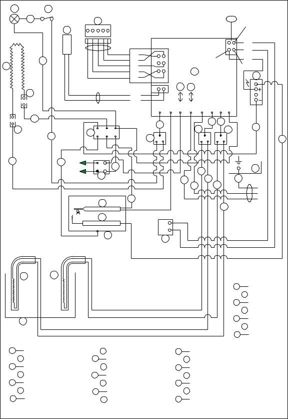
TYPICAL WIRING DIAGRAM FOR
RM7030 (PRODUCT NO. 921890401)
M |
L |
|
|
|
|
|
|
|
|
|
|
|
|
|
|
6 |
|
B |
|
|
|
|
|
|
|
|
P3 |
|
|
|
|
|
|
|
|
|
|
|
|
|
1 |
|
|
|
|
|
|
|
|
|
|
|
|
|
|
|
|
|
|
|
|
C |
|
|
|
|
|
|
|
|
|
|
|
|
|
|
|
|
|
|
|
|
|
|
|
|
A3 WHITE |
||
|
|
|
|
BLACK |
|
|
|
|
|
|
|
B3 |
|
YELLOW |
|
|
|
|
A5 |
|
|
|
|
|
|
|
|
|
|
|
|
|
|
BROWN |
|
|
|
|
4 |
|
C3 |
BLUE |
||
|
1 |
|
|
B5 |
|
|
|
|
|
|||||
Q |
|
|
RED |
|
|
|
|
|
|
|
||||
|
|
|
C5 |
|
|
|
|
|
|
2 |
|
|
||
|
|
|
ORANGE |
|
|
|
A |
|
|
|
|
|||
|
|
|
|
D5 |
|
|
|
|
|
|
|
E |
||
|
|
|
|
GREEN |
E5 |
|
|
|
|
|
|
|
|
|
|
|
|
|
WHITE |
|
|
O |
P |
|
|
|
|
|
|
|
S |
|
|
A2 |
|
|
|
|
|
|
|
|
|
|
|
|
|
WHITE |
|
|
|
|
|
|
|
|
|
||
|
|
|
|
B2 |
|
|
|
|
|
|
J10 |
|
|
|
|
|
|
|
|
J3 |
J4 |
J5 |
|
J7 |
J8 |
|
|
||
|
|
|
|
|
J2 |
J6 |
|
|
||||||
|
1 |
|
|
|
7 |
|
|
|
|
1 2 |
|
|
|
|
|
|
|
|
|
|
|
|
|
|
|
4 |
|||
R |
|
|
J |
|
|
|
|
T |
|
|
T |
|
||
2 |
|
|
|
|
|
|
|
|
|
|
||||
|
|
|
T |
|
|
|
|
|
|
|
|
|
||
|
|
|
|
|
|
|
|
|
|
|
|
5 |
||
2 |
1 |
+ |
|
1 |
|
|
|
|
|
|
|
|
|
U |
|
|
- |
|
|
|
|
|
1 |
|
|
|
|
||
|
|
I |
|
|
|
|
|
|
|
|
|
|
||
|
|
12V DC |
|
|
|
2 |
|
|
1 |
|
3 |
|
|
|
|
|
|
|
|
|
|
1 |
2 |
|
|
||||
|
|
|
|
|
|
|
|
|
|
|
|
|||
|
|
|
F |
|
2 |
|
|
|
|
|
|
|
|
|
|
|
|
|
|
|
|
|
|
|
|
2 |
|
|
|
|
|
|
|
|
|
|
|
|
|
|
|
|
|
|
|
|
|
G |
|
|
|
|
|
|
|
|
|
|
|
|
|
|
|
H |
|
D |
|
|
|
|
|
|
|
|
|
|
|
|
|
|
|
|
|
|
|
|
|
|
|
|
120 VOLTS AC |
|
|
|
|
|
|
|
|
|
|
|
|
|
N |
N |
|
|
|
|
|
|
|
|
|
|
|
|
|
|
|
|
|
|
|
|
|
|
|
|
|
1 |
WHITE |
|
|
|
|
|
|
|
|
|
|
|
|
|
2 |
BLACK |
|
|
|
|
|
|
|
|
|
|
|
|
|
3 |
GREEN |
|
|
|
|
|
|
|
|
|
|
|
|
|
4 |
GREEN/YELLOW |
|
K |
|
|
|
|
|
|
|
|
|
|
|
5 |
GREY |
|
|
|
|
|
|
|
|
|
|
|
|
6 |
BROWN |
||
|
|
|
|
|
|
|
|
|
|
|
|
|||
|
|
|
|
|
|
|
|
|
|
|
|
7 |
|
BLUE |
A |
CIRCUIT BOARD POWER |
H |
RETAINER FOR BURNER |
|
O |
|
FUSE 3A |
|
|
|
|
|||
B |
CIRCUIT BOARD DISPLAY |
I |
TERMINAL BLOCK |
|
P |
|
FUSE 5A |
|
|
|
|
|||
C |
THERMISTOR |
|
J |
TERMINAL STRIP |
|
Q |
|
HEATING CABLE |
|
|
||||
D |
GAS VALVE |
|
K |
ABSORPTION UNIT |
|
R |
|
SWITCH |
|
|
|
|
||
E |
REIGNITER |
|
L |
SWITCH |
|
|
S |
|
TERMINAL BLOCK |
|
|
|||
F |
THERMOCOUPLE |
|
M |
LIGHT |
|
|
T |
|
TERMINAL BLOCK |
|
|
|||
G |
ELECTRODE |
|
N |
HEATER 120V AC |
|
U |
|
RETAINER FOR |
|
|
||||
|
|
|
|
|
|
|
|
|
CIRCUIT BOARD POWER |
|
|
|||
17

TYPICAL WIRING DIAGRAM FOR
RM7030 (PRODUCT NO. 921890201 & 921890301)
18

TYPICAL RM4804 3-WAY 12/120 VOLTS WIRING DIAGRAM
TYPICAL RM4804 2-WAY 120 VOLTS WIRING DIAGRAM
19

TYPICAL WIRING DIAGRAM - RM2652, RM2852, RM2612, RM2812
20
RM3604 & RM3804 3-WAY 12/120 VOLTS
|
|
|
D |
|
BLACK |
|
|
|
|
|
5 |
|
|
B |
|
|
A |
7 |
BLACK |
|
4 |
— |
|
|
|
|
2 |
|
+ |
12 VOLT |
|
|
|
K |
|
Z |
85 |
30 |
|
||||||||
|
BROWN |
|
|
||||||||||||
|
B |
7 |
ORANGE |
PL |
|
|
|
|
I |
— |
DC |
||||
|
C |
7 |
RED |
|
BROWN |
+ |
|
|
|
|
|
|
|
IGN. LOCK |
|
|
D |
7 |
ORANGE |
|
|
|
|
|
86 |
87 |
|
|
|
||
|
YELLOW |
|
|
|
|
|
|
|
|
1 |
|||||
|
E |
7 |
|
|
|
|
|
|
|
|
|
|
|
||
|
GREEN |
|
RED |
|
|
|
|
|
L |
|
|
|
|
||
|
F |
7 |
|
|
|
|
|
|
|
|
|
|
|||
|
BLUE |
|
YELLOW |
|
|
|
|
|
BLACK |
|
|
|
|
||
|
G |
7 |
|
|
|
|
|
|
|
|
|
|
|||
|
|
|
D |
|
|
|
|
|
|
|
|
|
|
||
|
|
|
|
|
|
|
|
|
|
|
|
|
|
|
|
|
|
|
DD |
|
BLACK |
|
|
|
R |
|
|
|
|
|
|
|
A |
6 |
BLACK |
BROWN |
|
|
|
|
S |
|
|
|
|
|
|
12V+ |
BROWN |
RED |
|
|
|
|
|
|
|
|
|
||||
B |
6 |
|
|
|
|
|
T |
|
|
|
Y |
||||
12V+ |
RED |
|
OR- |
|
|
|
|
|
|
|
|
||||
C |
6 |
|
|
|
|
|
|
U |
|
|
|
||||
|
ORANGE |
ANGE |
|
|
|
|
|
|
|
|
|
||||
|
D |
6 |
|
|
|
|
|
|
V |
|
|
|
|||
|
GREEN |
YEL- |
|
|
|
|
|
|
|
|
|
||||
12V+ |
E |
6 |
|
|
|
|
|
|
|
|
X |
|
|||
YELLOW |
LOW |
|
|
|
|
|
|
|
|
|
|||||
F |
6 |
|
|
|
|
|
|
|
|
|
|
||||
|
|
|
GREEN |
|
|
|
|
|
|
|
|
|
|
||
|
|
|
BLACK |
|
|
|
|
|
|
|
|
|
|
||
12V+ |
A |
10 |
BLUE |
|
|
|
|
|
|
|
|
M |
|
||
BROWN |
|
|
|
|
|
|
|
|
|
||||||
|
B |
10 |
|
|
|
|
|
|
|
|
|
|
|
||
|
RED |
|
|
|
|
|
|
|
|
|
|
|
|
||
|
C |
10 |
|
|
|
|
|
E OFF POSITION |
|
|
|
|
|||
|
ORANGE |
|
|
|
|
|
|
|
|
||||||
|
D |
10 |
|
|
|
|
|
|
|
|
|||||
|
YELLOW |
|
|
|
|
|
|
A |
|
|
|
|
|||
|
E |
10 |
|
|
|
|
|
|
|
|
|
|
|
||
|
GREEN |
|
|
|
|
|
|
|
|
|
|
|
|||
|
F |
10 |
|
|
|
|
|
|
|
|
|
|
|
||
|
BLUE |
|
|
|
|
|
|
|
N |
|
|
|
|
||
|
G |
10 |
|
|
|
|
|
|
|
|
|
|
|
||
|
VIOLET |
|
|
|
|
|
|
|
P |
|
|
||||
|
H |
10 |
|
|
|
|
|
|
|
|
|
|
|||
|
GRAY |
|
|
|
|
|
|
|
O |
|
|
|
|||
|
I |
10 |
|
|
|
|
|
|
|
|
|
|
|
||
|
WHITE |
|
|
|
|
|
|
|
|
Q |
|
||||
|
K |
10 |
D |
|
D |
|
|
|
|
|
|
|
|
|
|
|
|
|
|
|
|
|
|
|
|
|
|
|
|
||
|
A |
4 |
BLACK |
|
|
G |
|
|
F |
|
|
|
|
|
|
|
BROWN |
|
|
|
|
|
|
|
|
|
|||||
|
B |
4 |
|
|
X |
|
|
|
|
|
|
||||
|
C |
4 |
RED |
|
|
|
|
|
|
|
C |
|
|
|
1 |
|
D |
4 |
ORANGE |
|
|
|
|
|
|
H |
|
|
C |
12V AC |
|
|
|
|
|
|
|
|
|
|
|
||||||
|
A |
|
BLACK |
B |
2 |
|
|
|
|
|
|
|
|
|
|
|
|
|
|
|
|
|
|
|
|
|
|
|
|||
|
|
WHITE |
|
|
|
|
|
120VOLTS AC |
|
|
|
|
|||
|
B |
|
|
1 |
|
|
|
|
|
|
|
|
|||
|
|
D |
|
3 |
|
|
|
|
|
C |
|
||||
|
C |
|
|
|
|
|
|
|
|
I |
|
120V AC |
|||
|
|
|
|
|
|
|
|
|
|
|
|
|
|
||
A |
D |
|
|
|
|
|
+ |
|
I |
|
I |
|
|
|
W |
A |
2 |
GRAY |
|
|
|
|
|
|
|
|
4 |
|
|||
|
BLACK |
|
|
|
|
|
|
|
J |
|
|
||||
|
B |
2 |
|
|
— |
|
|
|
|
|
|
||||
|
D |
|
|
|
|
|
|
|
|
|
|
||||
|
|
|
|
|
D |
|
|
|
|
|
|
|
|
||
|
|
|
|
|
|
|
|
|
|
|
|
|
|
||
A |
CIRCUIT BOARD |
|
B |
TERMINAL BLOCK |
|
C |
HEATER |
|
D |
CONNECTOR |
|
E |
MAIN SWITCH |
|
F |
DOOR SWITCH |
|
G |
LIGHT |
|
H |
THERMOSTAT |
|
I |
GAS VALVE COIL |
|
J |
THERMOCOUPLE |
|
K |
REIGNITER |
|
L |
TIME FUSE 3–3.15 AMP |
|
M |
||
GAS FLAME WARN. LAMP |
||
N |
AC/GAS FUNCTION |
|
O |
SWITCH |
|
P |
AC/GAS FUNCTION LAMP |
|
Q |
||
GAS FUNCTION SWITCH |
||
R |
GAS FUNCTION LAMP |
|
S |
AES FUNCTION SWITCH |
|
T |
AES FUNCTION LAMP |
|
U |
||
120V AC MODE LAMP |
||
V |
12V DC MODE LAMP |
|
W |
DELAY MODE LAMP |
|
X |
||
ABSORPTION UNIT |
||
Y |
||
GAS MODE LAMP |
||
Z |
||
MODE SWITCH |
||
|
||
|
RELAY |
|
1 |
|
|
2 |
WHITE |
|
3 |
BLACK |
|
4 |
GREEN |
5GREEN/YELLOW BROWN
RM3604 & RM3804 2-WAY 120 VOLTS
|
A |
D |
BLACK |
|
BLACK |
— K |
|
|
|
B |
|
A |
CIRCUIT BOARD |
|
7 |
BROWN |
4 |
|
|
|
+ 12 VOLT |
||||||
|
B |
7 |
ORANGE |
PL |
|
|
I |
— |
DC |
B |
TERMINAL BLOCK |
||
|
RED |
|
|
|
|
||||||||
|
C |
7 |
|
BROWN |
+ |
|
|
|
|
IGN. LOCK |
C |
HEATER |
|
|
D |
7 |
ORANGE |
|
|
|
|
|
|
||||
|
YELLOW |
|
|
|
|
|
|
|
D |
CONNECTOR |
|||
|
E |
7 |
|
|
|
|
|
|
|
||||
|
GREEN |
|
|
|
|
|
L |
|
|
E |
MAIN SWITCH |
||
|
F |
7 |
|
|
|
|
|
|
|
||||
|
G |
7 |
BLUE |
|
YELLOW |
|
|
|
BLACK |
|
|
F |
DOOR SWITCH |
|
|
|
D |
|
|
|
|
|
|
||||
|
|
|
|
|
|
|
|
|
|
|
G |
LIGHT |
|
|
|
DD |
|
|
BLACK |
|
|
|
R |
|
|
||
|
|
|
|
|
|
|
|
|
|
||||
|
A |
6 |
BLACK |
BROWN |
|
|
|
S |
|
|
H |
THERMOSTAT |
|
12V+ |
BROWN |
RED |
|
|
|
|
|
I |
GAS VALVE COIL |
||||
B |
6 |
|
|
|
T |
|
Y |
||||||
12V+ |
C |
6 |
RED |
|
OR- |
|
|
|
|
|
J |
THERMOCOUPLE |
|
|
ORANGE |
ANGE |
|
|
|
|
|
|
|||||
|
D |
6 |
|
|
|
V |
|
|
K |
REIGNITER |
|||
|
GREEN |
YEL- |
|
|
|
|
|
||||||
12V+ |
E |
6 |
|
|
|
|
X |
|
L |
TIME FUSE 3–3.15 AMP |
|||
YELLOW |
LOW |
|
|
|
|
|
|||||||
F |
6 |
|
|
|
|
|
|
M |
|
||||
|
BLACK |
GREEN |
|
|
|
|
|
|
GAS FLAME WARN. |
||||
12V+ |
A |
10 |
BLUE |
|
|
|
|
|
M |
|
LAMP |
||
BROWN |
|
|
|
|
|
|
|||||||
|
|
|
|
|
|
|
|||||||
|
B |
10 |
RED |
|
|
|
|
|
|
|
|
|
|
|
C |
10 |
|
|
|
|
|
E OFF POSITION |
|
|
P |
|
|
|
ORANGE |
|
|
|
|
|
|
GAS FUNCTION SWITCH |
|||||
|
D |
10 |
|
|
|
|
|
|
|||||
|
YELLOW |
|
|
|
|
A |
|
|
Q |
GAS FUNCTION LAMP |
|||
|
E |
10 |
|
|
|
|
|
|
|
||||
|
GREEN |
|
|
|
|
|
|
|
R |
AES FUNCTION SWITCH |
|||
|
F |
10 |
|
|
|
|
|
|
|
||||
|
BLUE |
|
|
|
|
|
|
|
|
||||
|
G |
10 |
|
|
|
|
|
|
|
|
S |
AES FUNCTION LAMP |
|
|
VIOLET |
|
|
|
|
P |
|
|
|||||
|
H |
10 |
|
|
|
|
|
|
T |
120V AC MODE LAMP |
|||
|
GRAY |
|
|
|
|
|
|
|
|||||
|
I |
10 |
WHITE |
|
|
|
|
|
Q |
|
|
|
|
|
K |
10 |
|
|
|
|
|
|
|
|
V |
DELAY MODE LAMP |
|
|
|
|
D |
|
|
|
|
|
|
||||
|
A |
DD |
BLACK |
|
|
|
|
|
|
W |
ABSORPTION UNIT |
||
|
4 |
|
|
G |
|
F |
|
|
X |
||||
|
B |
4 |
BROWN |
|
|
X |
|
|
GAS MODE LAMP |
||||
|
|
|
|
|
Y |
||||||||
|
C |
4 |
RED |
|
|
|
|
|
H C |
|
|
MODE SWITCH |
|
|
ORANGE |
|
|
|
|
|
|
|
|||||
|
D |
4 |
|
B |
|
|
|
|
|
|
|
|
|
|
A |
BLACK |
2 |
|
|
|
|
|
|
|
|
||
|
|
|
|
|
|
|
|
|
|
||||
|
WHITE |
|
|
|
|
120VOLTS AC |
|
|
|
|
|||
|
B |
|
1 |
|
|
|
|
|
|
|
|||
|
|
D |
|
3 |
|
|
C 120V AC |
1 |
|
||||
|
C |
|
|
|
|
|
I |
WHITE |
|||||
|
|
|
|
|
|
|
|
|
W |
2 |
BLACK |
||
A |
D |
|
|
|
|
|
+ |
|
I |
|
3 |
GREEN |
|
|
|
GRAY |
|
|
|
|
I |
|
|
||||
|
A |
2 |
|
|
|
|
4 |
|
4 |
GREEN/YELLOW |
|||
|
BLACK |
|
|
|
|
J |
|
||||||
|
B |
2 |
|
|
— |
|
|
|
|
||||
|
D |
|
|
|
|
|
|
|
|
||||
|
|
|
|
|
D |
|
|
|
|
|
|
||
|
|
|
|
|
|
|
|
|
|
|
|
||
21

ROYALE & ELITE
TYPICAL 3-WAY
WIRING DIAGRAM
293267600
4
22

ROYALE & ELITE
TYPICAL 2-WAY
WIRING DIAGRAM
293267500
23

AMES & AES
TYPICAL 3-WAY WIRING
DIAGRAM
White
Black
Green
Green/Yellow
Gray
Brown
AMES & AES
TYPICAL 2-WAY WIRING DIAGRAM
Circuit Board Power
Circuit Board Display
Thermistor
Gas Valve
Reigniter
Thermocouple
Electrode
Retainer for Burner
Terminal Block
Terminal Strip
Absorption Unit
Fuse 3A
Fuse 5A
Heater 120V AC
Switch
Light
Heating Cable
Switch
Terminal Block
Terminal Block
White
Black
Green
Green/Yellow
Gray
Brown
24
RM2604 & RM2804 2-WAY 120 VOLTS
|
|
|
|
|
|
G |
H |
|
|
|
|
|
|
|
|
|
|
|
|
|
120 V OLTS A C |
|
|
12 V OLTS DC |
|
||
|
|
|
|
|
|
1 |
|
|
|
|
|
||
|
|
|
|
|
|
|
|
|
|
|
G |
|
|
|
|
|
|
|
|
|
|
|
|
|
|
|
|
|
|
|
|
2 |
|
|
E |
|
|
|
|
H |
|
|
|
|
|
|
|
|
|
|
|
|
|
|
|
|
7 |
4 |
2 |
1 |
B |
|
|
|
|
7 |
4 |
|
|
|
|
|
|
A |
|
|
|
|
|
|
A |
|
|
|
|
|
|
|
4 C |
2 |
|
|
|
|
|
|
|
|
7a |
4a |
|
1a |
|
|
|
|
|
7a |
4a |
|
F |
|
|
|
|
|
|
|
|
|
|||||
|
L |
2a |
|
|
|
|
K |
4 |
|
|
|
|
I |
|
|
|
|
|
|
|
|
|
|
||||
|
4 |
|
|
|
|
|
|
|
|
|
|
|
|
|
|
|
|
|
|
|
1 |
|
|
|
|
|
|
2 |
|
2 |
|
|
|
|
1 |
|
|
|
|
|
|
|
|
|
|
|
2 |
|
|
|
|
|
|
||
|
|
|
|
|
|
|
|
|
|
|
|
SWITCH |
|
|
|
|
|
|
|
|
1 |
|
|
120 V OLTS A C |
A |
||
|
|
|
|
|
|
1 |
F |
|
|
B |
THERMOSTAT |
||
|
12 V OLTS DC |
|
|
C |
|
|
|
|
|||||
|
REIGNITER |
|
|
|
1 |
D |
|
2 |
1 |
E |
C |
TERMINAL BL OCK |
|
|
LAMP |
|
|
|
|
|
|||||||
|
|
|
|
|
3 |
|
4 |
1 |
|
A |
|
D |
TERMINAL BL OCK |
|
|
|
|
N |
|
|
|
|
|
E |
HEATER |
||
|
|
|
|
1 |
|
|
2 |
|
|
|
|||
|
120 V OLTS A C L |
|
|
|
|
|
F |
REIGNITER |
|||||
|
2 |
|
|
|
|
C |
|
||||||
|
|
|
|
|
|
|
|
|
2a |
1a |
B |
G |
LAMP |
1 |
WHITE |
|
|
|
|
|
I |
|
H |
DOOR SW ITCH |
|||
|
|
|
|
|
|
|
D |
|
|||||
2 |
BLACK |
|
|
|
|
|
|
|
|
|
I |
INDICATION L AMP |
|
|
|
|
|
|
|
|
|
|
|
||||
3 |
GREEN |
|
|
|
|
|
J |
|
|
N |
|
J |
TERMINAL ST RIP |
4 |
GREEN/YELLOW |
|
|
|
|
|
K |
ABSORPTION UNIT |
|||||
|
|
|
|
|
L |
|
|||||||
|
|
|
|
|
|
|
|
|
|
|
L |
BRACKET |
|
|
|
|
|
|
|
|
|
|
|
|
|
||
|
|
|
|
|
|
|
|
|
J |
K |
|
120 V OLTS |
|
|
|
|
|
|
120 V OLTS A C MODE |
||||
|
|
|
|
|
|
|
|
|
|
|
|
|
|
|
|
|
|
||||||
|
|
|
|
|
|
|
|
|
|
|
|
12VOLTS DC |
|
12 V OLTS DC MODE |
|
|
|||||||
|
|
|
|
|
|
|
|
|
|
|
|
|
|
|
|
|
|
|
|
||||
|
|
|
|
|
|
|
|
|
1 |
|
|
AC |
|
|
|
|
|
|
|
|
|
|
|
|
|
|
|
|
|
2 |
2 |
|
|
|
|
6 |
5 |
A |
G |
|
2 |
1 |
|
|
F |
||
|
|
|
|
|
|
|
|
|
|
|
|
|
|
|
|
|
|||||||
|
|
|
|
1 |
|
|
|
|
|
|
|
|
|
|
|
|
|
A |
|
|
|||
|
|
|
|
|
|
|
|
|
|
|
|
|
|
|
|
|
|
|
|
|
|
|
|
|
7 6 |
5 |
4 |
2 |
1 |
|
|
|
|
|
|
|
|
|
|
|
|
|
|
|
|
|
|
|
|
|
|
|
|
A B |
|
|
|
|
|
6a |
5a |
B |
H |
|
2a |
1a |
B |
||||
|
|
|
|
|
|
|
|
|
|
|
|
|
|
|
|
|
|
|
|
|
|||
|
|
|
|
|
|
|
4 |
|
2 |
|
|
|
|
|
|
|
|
|
|
|
|
E |
|
|
|
|
|
|
|
|
|
|
|
|
|
|
|
|
|
|
|
|
|
|
|
||
|
7a 6a 5a 4a |
2a |
1a |
|
|
|
|
|
|
|
|
|
|
|
|
|
|
N |
|
|
|||
|
|
|
|
|
|
|
|
|
|
|
|
|
|
|
|
|
|
|
|
|
|
||
|
D |
|
|
|
|
|
86 |
|
87 |
|
|
|
|
|
|
|
|
|
|
L |
|
|
|
|
|
|
|
1 |
|
|
|
|
|
|
|
|
|
|
|
|
|
|
|
|
|
||
|
4 |
|
|
|
|
|
H |
|
|
|
|
|
|
|
|
|
|
|
|
|
|
||
|
|
|
|
|
|
4 |
|
|
|
|
|
|
12 V OLTS DC MODE |
|
A |
SWITCH |
|||||||
|
|
|
|
|
|
|
|
30 |
|
|
1 |
|
|
|
|||||||||
|
|
|
|
2 |
|
|
85 |
|
|
|
|
|
|
|
|
|
|
B THERMOSTAT |
|||||
|
|
|
|
|
|
|
4 |
2 |
|
|
1 |
|
|
|
|
|
|
|
|||||
2 |
2 |
DC |
|
|
|
|
|
|
|
|
|
|
|
J |
|
C |
TERMINAL BL OCK |
||||||
|
|
12 V OLTS |
|
|
|
|
|
|
|
|
|
|
|
|
|
|
|
|
|||||
|
|
HEATER |
|
|
|
C |
|
|
2 |
|
|
|
|
|
K |
|
|
D TERMINAL BL OCK |
|||||
|
|
|
|
|
|
|
|
|
|
1 |
I |
|
|
|
|
|
|
E |
TERMINAL BL OCK |
||||
|
|
|
|
|
|
|
|
|
|
1 |
|
|
|
|
|
|
|||||||
|
12 V OLTS DC |
|
|
|
D |
|
|
|
|
|
|
|
|||||||||||
|
|
|
|
E |
|
|
7 |
4 |
|
|
|
|
F |
HEATER |
|||||||||
|
|
|
|
|
|
|
|
|
|
|
|
|
|||||||||||
|
REIGNITER |
|
|
|
|
|
1 |
|
|
|
|
|
A |
|
|
|
|
|
HEATER |
||||
|
LAMP |
|
|
|
|
|
|
|
|
|
4 |
|
|
|
|
|
G |
|
|||||
|
|
|
|
|
|
|
|
|
|
|
|
|
|
|
|
|
|||||||
|
|
|
|
|
|
N |
3 |
|
|
|
|
4 |
|
|
|
|
|
|
|
H RELAY |
|||
|
120 V OLTS A C |
1 |
|
|
|
|
1 |
|
|
|
|
|
|
I |
REIGNITER |
||||||||
|
L |
|
|
|
|
|
|
|
|
|
|
||||||||||||
|
2 |
|
|
|
|
|
|
|
|
|
I |
|
|||||||||||
|
|
|
|
|
|
|
|
|
|
|
|
|
7a |
4a |
|
|
|
J |
LAMP |
|
|||
|
|
|
|
|
|
|
|
|
|
|
|
|
|
|
|
|
|
|
|||||
|
|
|
|
|
|
|
|
|
|
|
L |
|
|
|
|
|
L |
|
K |
|
DOOR SW ITCH |
|
|
|
WHITE |
|
|
|
|
|
|
|
|
|
|
|
|
|
|
|
|
|
L |
INDICATION L AMP |
|||
1 |
|
|
|
|
|
|
|
|
|
|
|
|
|
|
|
|
|
|
|||||
|
|
|
|
|
|
|
I |
|
|
|
|
|
|
|
|
|
M TERMINAL ST RIP |
||||||
2 |
BLACK |
|
|
|
|
|
|
|
|
|
|
|
|
|
|
|
|
||||||
|
|
|
|
|
|
|
|
|
H |
|
|
|
|
|
|
|
|
N ABSORPTION UNIT |
|||||
3 |
GREEN |
|
|
|
|
|
|
|
|
|
|
|
|
|
|
|
|
|
|||||
|
|
|
|
|
|
|
|
|
|
|
|
|
|
|
|
|
O |
BRACKET |
|||||
4 |
GREEN/YELLOW |
|
|
|
|
|
|
|
|
|
|
|
|
||||||||||
|
|
|
|
|
|
|
|
|
|
|
|
|
|
|
|
|
|||||||
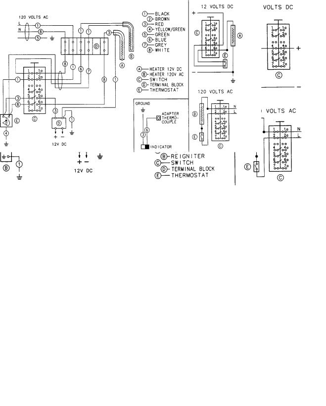
TYPICAL MANUAL 2-WAY WITH REIGNITOR
FOR REFRIGERATORS WITH TOP MOUNT CONTROLS
TYPICAL MANUAL 3-WAY WITH PIEZO IGNITOR
FOR REFRIGERATORS WITH TOP MOUNT CONTROLS
26
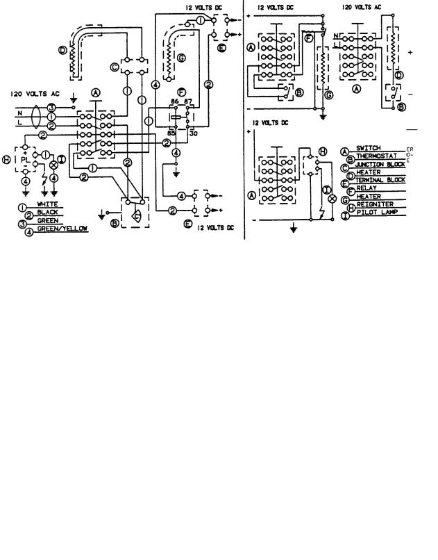
TYPICAL MANUAL 3-WAY WITH REIGNITOR
FOR REFRIGERATORS WITH TOP MOUNT CONTROLS
TYPICAL MANUAL 3-WAY WITH REIGNITER AND RELAY
FOR REFRIGERATORS WITH BOTTOM MOUNT CONTROLS
27

TYPICAL MANUAL 3-WAY WITH REIGNITER
FOR REFRIGERATORS WITH BOTTOM MOUNT CONTROLS
TYPICAL MANUAL 2-WAY WITH PIEZO IGNITOR
FOR REFRIGERATORS WITH TOP MOUNT CONTROLS
28
 Loading...