


|
INSTALLATION AND |
|
|
® |
|
|
|
OPERATING INSTRUCTIONS |
|
|
|
REFRIGERATOR FOR LP-GAS AND ELECTRIC OPERATION
RM 2352 RM 2353
FOR YOUR SAFETY
If you smell gas:
1.Open windows.
2.Don’t touch electrical switches.
3.Extinguish any open flame.
4.Immediately call your gas supplier.
FOR YOUR SAFETY
Do not store or use gasoline or other flammable vapors and liquids in the vicinity of this or any other appliance.
WARNING: Improper installation, adjustment, alteration, service or maintenance can cause injury or property damage. Refer to this manual. For assistance or additional information consult a qualified installer, service agency or the gas supplier.
Contents: |
|
|
Page |
Installation |
4 |
Operating Instructions |
9 |
Maintenance & Service |
11 |
AVIS
Cet appareil doit être réparé seulement par un réparateur autorisé. Modification de l’appareil pourrait être extrèmement dangeruse, et pourrait causer mal ou mort.
|
|
|
® |
|
|
|
|
Corporate Office |
|
|
|
|
|
|
|
2320 Industrial Parkway Elkhart, IN 46515 |
|
||
USA |
|
|
For Service Center Assistance |
CANADA |
Service Office |
|
|
Call: 800-544-4881 |
Dometic Distribution Inc. |
Dometic Corporation |
|
|
|
866 Langs Drive |
509 South Poplar Street |
|
|
|
Cambridge, Ontario |
LaGrange, IN 46761 |
|
|
|
N3H 2N7 Canada |
Phone: 260-463-4858 |
|
|
|
Phone: 519-653-4390 |
825 12 08-00

Heater(s)
Flue baffle
12 volt
terminal block, 
 Protection cover 3-Way only
FIG. 1 |
Manual gas |
Inlet fitting |
Screw for burner cover |
shutoff valve |
|
Burner jet |
|
|
|
|
|
|
|
Flexible cord |
|
Refrigerator control panel
A E D C B
Travel latch
LEGEND
A. ON/OFF, Fuel Selector Switch
B. Thermostat Knob, Gas/Electric
C. Flame Failure Safety Valve Push-button
D. Piezo Igniter
E. Flame Indicator
FIG. 2
3
INSTALLATION
GENERAL INSTRUCTION
This appliance is designed for storage of foods and storage of frozen foods and making ice.
The refrigerators outlined herein have been design certified by A.G.A. under the ANSI Z21.19 Refrigerator Standard for installation in a mobile home or recreational vehicle and are approved by the Canadian Gas Association.
The certifications are, however contingent on the installation being made in accordance with the following instructions as applicable.
In the U.S.A., the installation must conform with:
1.National Fuel Gas Code ANSI Z223.1 - (latest edition).
2.Manufactured Home Construction and Safety Standard Title 24 CFR, Part 3280.
3.Recreational Vehicles ANSI A119.2 - (latest edition).
The unit must be electrically grounded in accordance with the National Electric Code ANSI/NFPA 70 - (latest edition) when installed, if an external alternating current electrical source is utilized.
4. Any applicable local code.
In CANADA, the installation must conform with:
1.Current CAN/CGA B149 Gas Installation Codes
2.Current CSA Standard Z240.4 GAS-EQUIPPED RECREATIONAL VEHICLES AND MOBILE HOUSING.
3.Where a flexible metal connector is used, it must comply with the provisions of the current Standard CAN1-6.10, METAL CONNECTORS FOR GAS APPLIANCES.
4.Any applicable local code
The unit must be electrically grounded in accordance with the current CANADIAN ELECTRICAL CODE C22 Parts 1 and 2.
VENTILATION
The installation shall be made in such a manner as to separate the combustion system from the living space of the mobile home or recreational vehicle. Openings for air supply or for venting of combustion products shall have a minimum dimension of not less than 1/4 inch. Proper installation requires one lower fresh air intake and one upper exhaust vent. The ventilation kits shown in this instruction manual have been certified for use with the refrigerator models listed in the Table. For “Certified Vent System Kits” see page 8.
The ventilation kits must be installed and used without modification. An opening toward the outside at floor level in the refrigerator compartment must be provided for ventilation of heavier-than-air fuel gases. The lower vent of the recommended kits is provided with proper size openings. The flow of combustion and ventilating air must not be obstructed.
The lower side vent is fitted with a panel, which provides an adequate access opening for ready serviceability of the burner and control manifold of the refrigerator. This should be centered on the back of the refrigerator.
CERTIFIED INSTALLATION
Certified installations require one roof vent and one lower side vent or optional one upper side vent and one lower side vent. For “Certified Vent System Kits” see page 8. For further information contact your dealer or distributor.
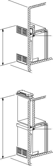
METHODS OF INSTALLATION
The method of installation is shown in FIG. 3a and 3b. It is essential that all maximum or minimum dimensions be strictly maintained, as the performance of the refrigerator is dependent on adequate flow of air over the rear of the refrigerator.
Condenser
Minimum ventilation height
FIG. 3a
Minimum ventilation height
Condenser
FIG. 3b
4
VENTILATION HEIGHTS
Refer to FIG. 3a, 3b and 4.
Refrigerator |
Minimum ventilation heights in inches and mm. |
||
model |
|
|
|
installation with |
Installation with roof |
||
|
|||
RM 2352 |
upper and lower |
vent and lower side |
|
RM 2353 |
side vent |
vent |
|
|
|
|
|
inch |
34 |
31 |
|
mm |
864 |
787 |
|
|
|
|
|
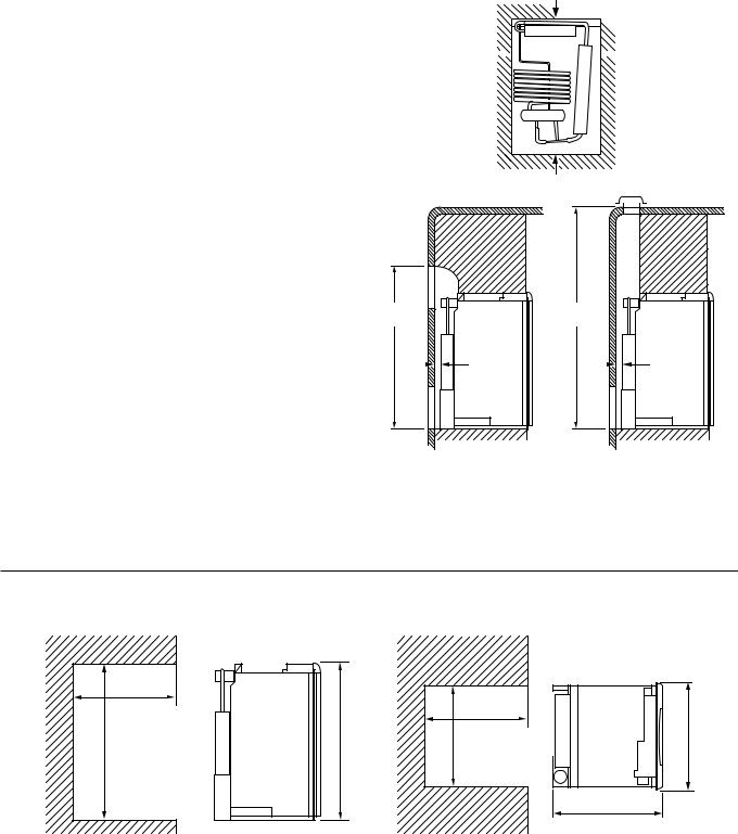
CLEARANCES
Minimum clearances in inches to combustible materials
are: |
|
|
G: |
Top |
0 |
K: |
Side |
0 |
L: |
Bottom 0 |
|
M: |
Rear |
1 |
N: |
See NOTE: “N” below. |
|
NOTE: Clearance “M” is between the rearmost part of the refrigerator and the wall behind the refrigerator.
NOTE: Ventilation height “N”
With upper and lower side vent is “N” the distances between the bottom of the lower side vent to the top of the upper side vent.
With roof vent and lower side vent is “N” the distance between the bottom of the lower side vent to the roof material.
For ventilation height, see table VENTILATION HEIGHTS.
See Figures 3a, 3b and 4.
G
K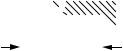 K
K
L
N |
M |
N |
M |
FIG. 4
FIG. 5
Side view |
View from above |
|
D |
|
|
|
|
|
D |
H |
A |
W |
B |
|
|||
|
|
|
C |
|
|
|
Overall |
|
|
|
Recess |
|
|
Refrigerator |
|
|
Dimensions |
|
|
Dimensions |
|
||
Model |
|
|
|
|
|
|
|
|
|
|
|
Height |
Width |
|
Depth |
Height |
|
Width |
Depth |
|
|
A |
B |
|
C |
H |
|
W |
D |
RM 2352 |
inch |
30-5/32 |
21-7/8 |
|
22-23/32 |
29-3/4 |
|
20-1/2 |
21-3/8 |
RM 2353 |
|
|
|
|
|
|
|
|
|
|
mm |
766 |
556 |
|
577 |
756 |
|
521 |
542 |
This method of installation and these clearances will give you adequate space for service and proper installation.
5
 Loading...