


RECORD THIS INFORMATION FOR FUTURE REFERENCE
BEFORE INSTALLING THE UNIT:
Model No. _______________ |
_____________________ Serial No. |
Date Purchased __________ |
Place of Purchase ______________ |
|
|
|
|
|
AMERICANA |
||||||
USA |
|
|
|
Model RM2652 & RM2852 |
|||||||
|
|
|
|
|
|
|
|
|
|
|
|
SERVICE OFFICE |
|
|
|
|
|
|
|
|
|
|
|
The Dometic Corp. |
|
|
|
REFRIGERATOR FOR LP/GAS |
|||||||
509 So. Poplar St. |
|
|
|
||||||||
LaGrange, IN 46761 |
|
|
|
||||||||
219-463-4858 |
|
|
|
AND ELECTRIC OPERATION |
|||||||
|
|
|
|
||||||||
CANADA |
|
|
|
|
|
|
|
|
|
|
|
Dometic Dist. |
|
|
|
|
|
|
|
|
|
|
|
866 Langs Dr. |
|
|
|
|
|
|
|
|
|
|
|
Cambridge, Ontario |
|
|
|
|
|
|
|
|
|
|
|
|
|
|
|
|
|
|
|
|
|
|
|
CANADA N3H 2N7 |
|
|
|
|
|
|
|
|
|
|
|
|
|
|
|
|
|
|
|
|
|
|
|
519-653-4390 |
|
|
|
|
|
|
|
|
|
|
|
|
FOR YOUR SAFETY |
|
|
! WARNING |
|
|
|||||
For Service Center |
|
|
|
|
|
||||||
If you smell gas: |
|
Improper installation, adjustment, |
|
||||||||
Assistance Call: |
|
|
|||||||||
800-544-4881 |
1. |
Shut off gas supply at the |
|
alteration, service or maintenance |
|
||||||
|
|
main LP gas tank valve. |
|
can cause injury or property dam- |
|
||||||
|
2. |
Open windows. |
|
age. Refer to this manual. For assis- |
|
||||||
|
3. |
Don't touch electrical |
|
tance or additional information |
|
||||||
|
|
switches. |
|
consult a qualified installer, service |
|
||||||
|
4. Extinguish any open flame. |
|
agency or the gas supplier. |
|
|||||||
|
5. Immediately call your gas |
|
|
|
|
|
|
|
|||
|
|
|
|
|
|
|
|
||||
|
|
|
|
! AVIS |
|
|
|
||||
|
|
supplier or service agency. |
|
|
|
|
|
|
|||
|
|
|
|
|
|
Cet appareil doit être réparé |
|
||||
|
|
|
|
|
|
|
|||||
|
|
|
|
|
|
seulement par un réparateur |
|
||||
|
|
|
|
|
|
autorisé. Modification de l'appareil |
|
||||
|
|
FOR YOUR SAFETY |
|
|
|||||||
|
|
|
pourrait être extrèmement |
|
|||||||
|
Do not store or use gasoline |
|
|
||||||||
|
|
dangeruse, et pourrait causer mal |
|
||||||||
|
or other flammable vapors |
|
|
||||||||
|
|
ou mort. |
|
||||||||
|
and liquids in the vicinity of |
|
|
||||||||
|
|
|
|
|
|
|
|
||||
|
|
|
|
|
|
|
|
||||
|
this or any other appliance. |
|
|
|
|
|
|
|
|||
|
|
|
|
|
|
|
|
|
|
|
|
REFRIGERATOR
INSTALLATION & |
|
|
MODEL |
|||
OPERATING INSTRUCTIONS |
||||||
RM2652 |
||||||
|
|
|
|
|
||
|
|
|
|
|
||
|
|
|
|
|
RM2852 |
|
|
|
INDEX |
Page |
|
||
|
|
|
|
|||
|
|
Installation .............................. |
2 |
|
|
|
FormNo.3106406.0066/95 |
|
Operating Instructions ............ |
8 |
|
|
|
TheDometicCorp. |
|
Maint. & Service ..................... |
12 |
|
|
|
LaGrange,IN46761 |
|
|
|
|
IMPORTANT INSTRUCTIONS |
|
|
|
|
|
|||
Copyright1995TheDometicCorporation |
|
|
|
|
||
|
|
|
|
READ CAREFULLY |
||
|
|
|
1 |
|
||
|
|
|
|
|
|
|
1. GENERAL INSTRUCTIONS
This appliance is designed for storage of foods and storage of frozen foods and making ice.
The refrigerators outlined herein have been design certified by A.G.A. under ANSI Z21 .19 Refrigerator Standard for installation in a mobile home or recreational vehicle and are approved by the Canadian Gas Association.
The certifications are, however, contingent on the installation being made in accordance with the following instructions as applicable.
In the U.S.A., the installation must conform with:
1.National Fuel Gas Code ANSI Z223.1-(latest edition)
2.Manufactured Home Construction and Safety Standard, Title 24 CFR, Part 3280
3.Recreational Vehicles ANSI Al 19.2-(latest edition).
The unit must be electrically grounded in accordance with the National Electric Code ANSI/NFPA 70-(latest edition) when installed if an external alternating current electrical source is utilized.
4. Any applicable local code.
In Canada, the installation must conform with:
1.Current CGA B 149 Gas Installation Codes
2.Current CSA Standard Z 240.4 GAS-EQUIPPED RECREATIONAL VEHICLES AND MOBILE HOUSING
3.Any applicable local code
The unit must be electrically grounded in accordance with the CANADIAN ELECTRICAL CODE C 22 Parts 1 and 2.
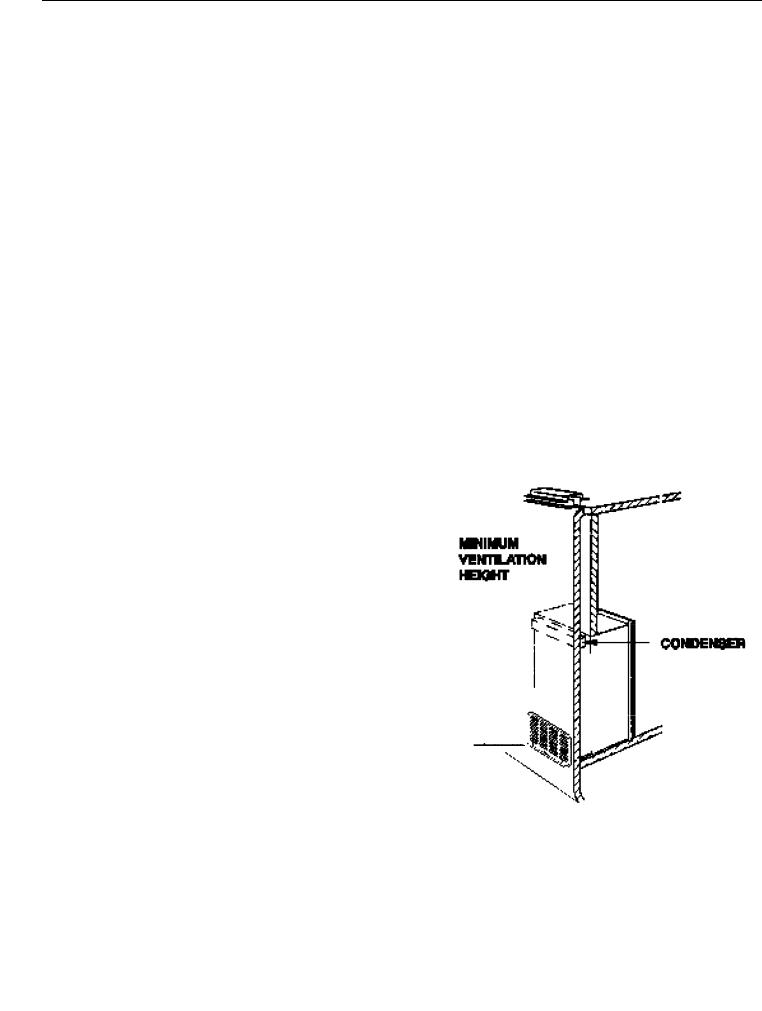
2. VENTILATION
The installation shall be made in such a manner as to separatethecombustion system from the living space of the mobile home or recreational vehicle. Louveropeningsforair supply or for venting of combustion products shall have a minimum dimension of not less than 1/4 inch.
Proper installation requires one fresh air intake and one upper exhaust vent. The ventilation kits shown in this instruction manual have been certified for use with the refrigerator model listed in the Table. For “Certified Vent System Kits” see Section B. The ventilation kits must be installed and used without modification. An opening toward theoutsideatfloor level in the refrigeratorcompartment must be provided forventilation of heavier-than-air fuel gases. The lower vent of the recommended kits is provided with proper size openings. The flow of combustion and ventilation air must not be obstructed.
The lower side vent is fitted with a panel which provides an adequate access opening for ready serviceability of the burner and control manifold of the refrigerator. This should be centered on the back of the refrigerator.
3. CERTIFIED INSTALLATION
Certified installations require one roof vent and one lower side vent.
For certified vent system kits, see Section B.
For further information, contact your dealer or distributor.
4. METHOD OF INSTALLATION
The method of installation is shown in FIG. 1. It is essential that all maximum or minimum dimensions are strictly maintained as the performanceof the refrigerator is dependent on adequate flow of air over the rear of the refrigerator.
NOTE: The upper vent should be centered over the condenser coil at the back of the refrigerator.
FIG. 1
2
5. VENTILATION HEIGHTS
Refer to FIG 1., Page 2
Installation with roof |
Minimum |
Ventilation |
|
vent and lower side vent |
heights in: |
||
|
|
|
|
REFRIGERATOR |
INCHES |
|
MM |
|
|
|
|
RM2652 |
57-3/4 |
|
1465 |
|
|
|
|
RM2852 |
63-3/4 |
|
1620 |
|
|
|
|
LOWER VENT CUTOUT
13-3/4"
21-9/16"
UPPER VENT CUTOUT
5-1/2"
23-3/4"
NOTE: All cutout dimensions are +/– 1/8".
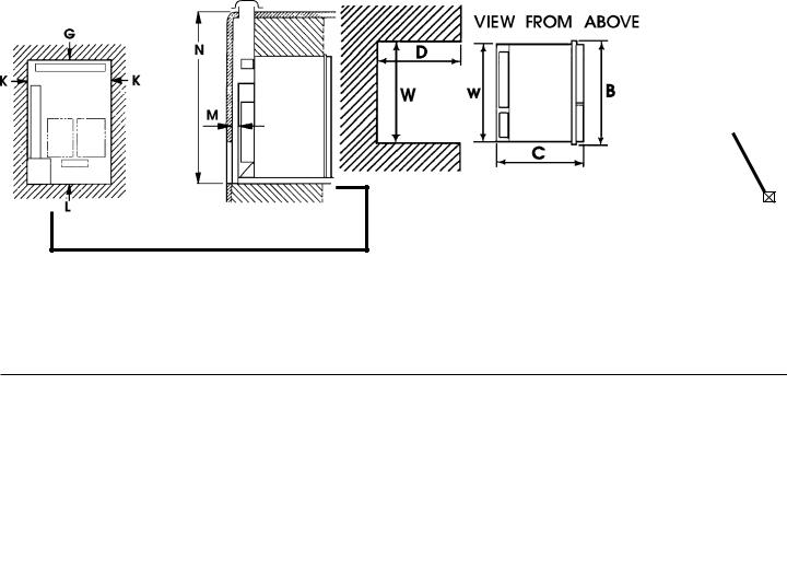
6. CLEARANCES
Minimum clearances in inches to combustible materials are:
G: |
Top |
0" |
K: |
Side |
0" |
L: |
Bottom |
0" |
M: |
Rear |
0" |
N: |
|
See NOTE |
NOTE: Clearance "M" is between the rearmost part of the refrigerator and the wall behind the refrigerator.
NOTE: Clearance "N" is the distance between the bottom of the lower vent to the roof material. For ventilation height, refer to Section A. Installation, Item 5. Ventilation Heights. See FIGS. 1 & 2.
|
NOTE: Wood Strip |
|
FIG. 2 |
MUST be in Place |
|
|
|
|
|
|
|
FIG. 3
|
|
|
|
|
|
|
|
|
|
|
|
|
|
|
|
|
|
|
|
|
|
|
|
|
|
|
|
|
|
|
|
|
|
|
|
|
|
|
|
|
|
|
|
|
|
|
|
|
|
|
|
|
|
|
|
|
|
|
|
|
|
|
|
|
|
|
|
|
|
|
|
|
|
|
|
|
|
|
|
|
|
|
|
|
|
|
|
|
|
|
|
|
|
|
|
|
|
|
|
|
|
|
|
|
|
|
|
Refrigerator |
|
|
|
|
Overall |
|
|
Recess |
|
Total |
|||||||
Model |
|
|
|
Dimensions |
|
|
Dimensions |
|
Ref. Vol. |
||||||||
|
|
|
|
|
|
|
|
|
|
|
|
|
|
|
|
|
|
|
|
|
|
Height |
|
|
Width |
Depth |
Height |
Width |
|
Depth |
|
||||
|
|
|
|
|
|
A |
|
|
B |
C |
H |
W |
|
D |
Cu. Ft. |
||
|
|
|
|
|
|
|
|
|
|
|
|
|
|
|
|
|
|
RM2652 (Inches) |
54-9/16 |
|
24-11/16 |
24-7/8 |
53-3/4 |
23-11/16 |
|
24 |
6.0 |
||||||||
|
|
|
|
|
|
|
|
|
|
|
|
|
|
|
|
|
|
|
(mm) |
1386 |
|
627 |
632 |
1365 |
601 |
|
|
608 |
|
||||||
|
|
|
|
|
|
|
|
|
|
|
|
|
|
|
|
|
|
RM2852 (Inches) |
60-5/8 |
|
24-11/16 |
24-7/8 |
59-15/16 |
23-11/16 |
|
24 |
7.3 |
||||||||
|
|
|
|
|
|
|
|
|
|
|
|
|
|
|
|
|
|
|
(mm) |
1530 |
|
627 |
632 |
1522 |
602 |
|
|
610 |
|
||||||
|
|
|
|
|
|
|
|
|
|
|
|
|
|
|
|
|
|
3
7.INSTALLING REFRIGERATOR IN
ENCLOSURE
NOTE: DO NOT install the appliance directly on carpeting. Carpeting must be removed or protected by a metal or wood panel beneath the appliance, which extends at least the full width and depth of the appliance.
Any space between the counter, storage area or ceiling can trap heat produced at the rear of the refrigerator. Any space between the top and sides of the refrigerator should be blocked for maximum refrigerator performance.
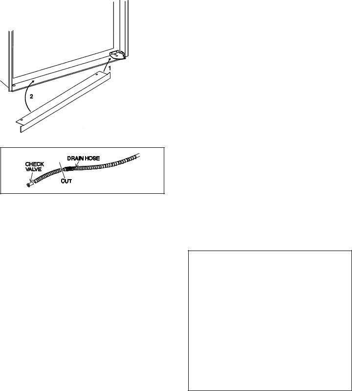
CONDENSATE WATER DRAIN HOSE: A 3/4" hole must be drilled through the flooring in the opening of the base plate on the rear of refrigerator (see FIG. 5D). The installer must make sure that the hose does not kink when run through the floor. Seal around the hose where it goes through the hole. If a longer hose is required, follow the illustration shown below:
OPTION A:
1)Remove black water check valve from hose.
2)Add additional hose
3)Reinstall black water check valve
OPTION B:
1)Cut drain hose at location shown below.
2)Install new drain hose between pieces cut.
NOTE: Black water check valve must be reinstalled to ensure proper refrigerator operation. DO NOT KINK HOSE.
OPTION C:
In vehicles where routing the drain hose through the floor is not possible, a metal clip is available. The clip is used to drain water out through the side vent.
Part No. 3106590.007 Clip for plastic side vent (Qty. 50) Part No. 3106590.015 Clip for plastic side vent (Single) Part No. 3106559.002 Clip for metal side vent (Qty. 50) Part No. 3106559.010 Clip for metal side vent (Single)
INSTALLATION: The refrigerator must be installed in a substantial enclosure and must be level. When installing the refrigerator in the enclosure, all areas within the recess in which the refrigerator is installed must be sealed. Make sure that there is a complete seal between the front frame of the refrigerator and the top, sides and bottom of the enclosure. A length of sealing strip is applied to the rear surface of the front frame for this purpose. Also apply a sealing strip to the foremost floor of the enclosure and apply a second sealing strip to the bottom of the trim strip on the front base as shown in FIG. 4. The sealing should provide complete isolation of the appliance's combustion system from the vehicle interior.
A wood strip must be in place across the upper opening of the enclosure. The top frame of the refrigerator will be anchored to the wood strip with screws. See FIG. 2.
The dimensions shown in FIG. 3 will give you adequate space for service and proper installation.
NOTE: If the door is hinged and it needs be changed to the opposite side, it must be done before the refrigerator is installed in the enclosure. See Step. 13.
FIG. 4
NOTE: Be careful not to damage the sealing strip applied to the floor of the enclosure when the refrigerator is put in place.
The refrigerator is secured in the enclosure with six screws. They must be installed in the following order:
a.First: Two screws are installed in front decoration strip and through the front base.
1)The front strip is to be installed after the refrigerator is set into the alcove. The strip is shipped as a loose part.
2)Install the lower front strip by sliding it under the bottom hinge plate as shown in FIG. 5. The hinge plate can be on the right or left side depending on the door swing.
FIG
4

3)When the front strip is in place, install one screw through the hinge and into the floor. The second screw is installed with a washer on the opposite side. (See FIG. 5A)
FIG. 5A
b. Second: Install the two screws in the top frame.
1)The top decoration panel must be removed from the refrigerator before the screws can be installed. Open refrigerator door and gently push the tabs out of the hole in the hinge with flat blade screwdriver. See FIG. 5B.
2)Carefully tilt the top decoration panel and lift up to remove from top frame. See FIG. 5B.
FIG. 5B
3)Install the second two screws in the top frame as shown in FIG. 5C.
FIG. 5C
4)Replace the top decoration panel. Be careful not to pinch the wires. Make sure the tabs snap back into the holes in the hinge plate.
C.Third: Two screws installed as shown in rear base. See FIG. 5D.
FIG. 5D
Hole for
Drain Water
Hose
Failure to follow the sequence in securing the refrigerator in the enclosure can cause leakage between the frame and cabinet.
8. GAS CONNECTION
Hook up to the gas supply line is accomplished at the manual gas shutoff valve, which is furnished with a 3/8" SAE (UNF 5/8" – 18) male flare connection. All completed connections should be checked for leaks with a noncorrosive leak detector. (See FIG. 6 – Gas tubing may have a different orientation than shown).
! WARNING
DO NOT USE A FLAME
TO CHECK FOR GAS LEAKS.
The gas supply system must incorporate a pressure regulator to maintain a supply pressure of not more than 13-1/2 inches water column (static) no load.
 PRESSURE
LP GAS REGULATOR
CYLINDER
TO
REFRIGERATOR
When testing the gas supply system at test pressures in excess of 1/2 psig, the refrigerator and its individual shutoff valve must be disconnected from the gas supply piping system.
5
 Loading...