


Dometic MCA1215, MCA1225, MCA1235, MCA1250, MCA1280 Service Manual
...ENERGY & LIGHTING PERFECTCHARGE
MCA1215, MCA1225, MCA1235, MCA1250, MCA1280, MCA2415, MCA2425, MCA2440
EN |
Battery charger |
|
|
Installation and Operating Manual . . . . . . . . 8 |
|
DE |
Batterielader |
|
|
Montageund Bedienungsanleitung . . . . .35 |
|
|
Chargeur de batteries |
|
FR |
|
|
|
Instructions de montage |
|
|
et de service . . . . . . . . . . . . . . . . . . . . . . . . |
.64 |
|
Cargador de batería |
|
ES |
|
|
|
Instrucciones de montaje y de uso . . . . . . .95 |
|
|
Carregador de baterias |
|
PT |
|
|
|
Instruções de montagem e manual de |
|
|
instruções . . . . . . . . . . . . . . . . . . . . . . . . . . |
125 |
|
Caricatore per batterie |
|
IT |
|
|
|
Istruzioni di montaggio e d’uso . . . . . . . . 153 |
|
NL |
Acculader |
|
|
Montagehandleiding en |
|
|
gebruiksaanwijzing . . . . . . . . . . . . . . . . . . |
182 |
DA |
Batterilader |
|
SV Batteriladdare
Monteringsoch bruksanvisning . . . . . . . 236
NO Batterilader
Monteringsog bruksanvisning . . . . . . . . 262
FI Akkulaturi
Asennusja käyttöohje . . . . . . . . . . . . . . . 288
RU Устройство для заряда аккумуляторных батарей
Инструкция по монтажу и эксплуатации 314
|
Ładowarka akumulatorowa |
|
PL |
|
|
|
Instrukcja montażu i obsługi. . . . . . . . . . . |
343 |
SK |
Nabíjačka batérií |
|
|
Návod na montáž a uvedenie |
|
|
do prevádzky. . . . . . . . . . . . . . . . . . . . . . . |
373 |
CS |
Nabíječka baterií |
|
|
Návod k montáži a obsluze . . . . . . . . . . . |
401 |
HU |
Akkumulátortöltő |
|
|
Szerelési és használati útmutató . . . . . . . 427 |
|
Monteringsog betjeningsvejledning . . . 210

MCA1215 – MCA2440 |
|
|
|
|
|
|
|
|
||||
1 |
|
|
|
|
|
|
|
|
MCA1215 |
|
||
6 |
|
|
|
5 |
|
|
|
|
4 |
3 |
2 |
1 |
|
|
|
|
|
|
|
|
|
|
|
|
|
1 |
2 |
3 |
|
STATUS |
|
|
|
|
|
TEMP/LIN1 |
LIN2 |
|
|
|
|
|
|
|
|
|
|
||||
|
|
|
|
1 |
2 |
3 |
4 |
|
5 |
|
|
|
|
|
|
|
DC OUTPUT |
|
|
|
AC INPUT |
|
|||
|
|
|
|
|
|
|
|
|
|
|
ESB |
|
|
|
7 |
|
8 |
|
|
|
9 |
|
|
||
|
|
|
|
MCA1225/1235/2415 |
|
|||||||
6 |
|
5 |
|
4 |
|
|
|
3 |
2 |
|
||
|
|
|
|
|
|
|
|
|
|
|
|
1 |
1 |
2 |
3 |
4 |
STATUS |
|
|
|
|
|
TEMP/LIN1 |
LIN2 |
|
|
|
|
|
|
|
|
|
|||||
|
|
|
|
1 |
2 |
3 |
4 |
|
5 |
|
|
|
|
|
|
|
DC OUTPUT |
|
|
|
AC INPUT |
|
|||
|
|
|
|
|
|
|
|
|
|
|
ESB |
|
|
7 |
|
8 |
|
|
|
|
9 |
|
|
||
|
|
|
MCA1250/1280/2425/2440 |
|
||||||||
6 |
|
|
|
5 |
|
|
|
4 |
3 |
2 |
|
|
|
|
|
|
|
|
|
|
|
|
|
|
1 |
|
1 |
2 |
3 4 |
STATUS |
|
|
|
|
|
TEMP/LIN1 |
LIN2 |
|
|
|
|
|
|
|
|
|
|
||||
|
|
|
|
1 |
|
2 |
3 |
4 |
5 |
|
AC INPUT |
|
|
|
|
|
|
|
|
|
|
|
|
|
|
|
|
|
|
DC OUTPUT |
|
|
|
|
|
|
|
|
|
|
|
7 |
|
|
|
|
|
|
8 |
|
|
|
|
|
|
|
|
|
|
|
|
|
|
3 |

|
MCA1215 – MCA2440 |
2 |
MCA1215/1225/1235/2415 |
|
|
1 |
2 |
|
MCA1250/1280/2425/2440 |
1 |
2 |
4

MCA1215 – MCA2440 |
|
3 |
MCA12xx |
LIN |
|
MPC01 |
MCA-HS1 (IBS) |
4 |
MCA12xx |
LIN |
|
|
|
|
|
|
MCA-RC1 |
|
|
|
|
|
|
|
|
|
|
|
|
|
|
|
|
|
|
|
|
|
|
|
|
|
|
|
|
|
|
|
|
|
|
|
MCA-HS1 (IBS) MCA-TS1 |
|||
|
|
|
|
|
||||
5

|
|
|
|
MCA1215 – MCA2440 |
5 |
1 |
MCA12xx |
|
|
|
LIN |
|
|
2 |
7 |
6 |
5 |
4 |
3 |
6 |
1 |
MCA24xx |
|
2 |
|
|
|
||
|
TEMP/LIN1 |
|
|
|
|
LIN2 |
|
|
|
3 |
MCA-RC1 |
|
|
|
MCA-TS1 |
|
|
|
|
||
7 |
8 |
|
|
|
9 |
TEMP/LIN 1/LIN 2 |
|
CN 2 |
|
ESB |
|
|
1 |
2 |
3 |
4 |
5 |
1 |
6 |
|
|
|
|
|
RJ-11 6P6C |
|
|
|
|
6

MCA1215 – MCA2440
0
Sleep
Mode
On / Off
MCA-RC1
1
2
3
MCA-RC1
|
|
1 |
|
|
|
|
2 |
|
|
|
|
3 |
|
|
|
|
4 |
|
|
1 |
RJ11 |
5 |
6 |
|
6 |
||||
6 |
|
1 |
a
1 2 3 4 |
STATUS |
OFF
ON
DC OUTPUT
7

MCA1215 – MCA2440
Please read this instruction manual carefully before installation and first use, and store it in a safe place. If you pass on the product to another person, hand over this instruction manual along with it.
Table of contents
1 Explanation of symbols . . . . . . . . . . . . . . . . . . . . . . . . . . . . . . . . . . . . . . . . . . .9 2 General safety instructions . . . . . . . . . . . . . . . . . . . . . . . . . . . . . . . . . . . . . . . .9 3 Intended use . . . . . . . . . . . . . . . . . . . . . . . . . . . . . . . . . . . . . . . . . . . . . . . . . .14 4 Scope of delivery . . . . . . . . . . . . . . . . . . . . . . . . . . . . . . . . . . . . . . . . . . . . . .14 5 Accessories . . . . . . . . . . . . . . . . . . . . . . . . . . . . . . . . . . . . . . . . . . . . . . . . . . .15 6 Technical description . . . . . . . . . . . . . . . . . . . . . . . . . . . . . . . . . . . . . . . . . . .15 7 Installing the device . . . . . . . . . . . . . . . . . . . . . . . . . . . . . . . . . . . . . . . . . . . .18 8 Connecting the device . . . . . . . . . . . . . . . . . . . . . . . . . . . . . . . . . . . . . . . . . 20 9 Using the device . . . . . . . . . . . . . . . . . . . . . . . . . . . . . . . . . . . . . . . . . . . . . . 26 10 Maintaining and cleaning the device . . . . . . . . . . . . . . . . . . . . . . . . . . . . . . 28 11 Troubleshooting . . . . . . . . . . . . . . . . . . . . . . . . . . . . . . . . . . . . . . . . . . . . . . 29 12 Warranty . . . . . . . . . . . . . . . . . . . . . . . . . . . . . . . . . . . . . . . . . . . . . . . . . . . . 30 13 Disposal . . . . . . . . . . . . . . . . . . . . . . . . . . . . . . . . . . . . . . . . . . . . . . . . . . . . . 30 14 Technical data . . . . . . . . . . . . . . . . . . . . . . . . . . . . . . . . . . . . . . . . . . . . . . . . .31
8
EN

MCA1215 – MCA2440 |
Explanation of symbols |
1Explanation of symbols
DDANGER!
Safety instruction: Failure to observe this instruction will cause fatal or serious injury.
!WARNING!
Safety instruction: Failure to observe this instruction can cause fatal or serious injury.
!CAUTION!
Safety instruction: Failure to observe this instruction can lead to injury.
ANOTICE!
Failure to observe this instruction can cause material damage and impair the function of the product.
INOTE
Supplementary information for operating the product.
2General safety instructions
The manufacturer accepts no liability for damage in the following cases:
•Faulty assembly or connection
•Damage to the product resulting from mechanical influences and excess voltage
•Alterations to the product without express permission from the manufacturer
•Use for purposes other than those described in the operating manual
!WARNING!
Note the following basic safety information when using electrical devices to protect against:
•Electric shock
•Fire hazards
•Injury
9
EN

General safety instructions |
MCA1215 – MCA2440 |
2.1General safety
DDANGER!
•In the event of fire, use a fire extinguisher which is suitable for electrical devices.
!WARNING!
•Only use the device as intended.
•Disconnect the device from the mains:
–Before cleaning and maintenance
–After use
–Before changing a fuse
•If you disassemble the device:
–Detach all connections
–Make sure that no voltage is present at any of the inputs and outputs
•The device may not be used if the device itself or the connection cable are visibly damaged.
•If this power cable for this device is damaged, it must be replaced by the manufacturer, customer service or a similarly qualified person in order to prevent safety hazards.
•This device may only be repaired by qualified personnel. Inadequate repairs may cause serious hazards.
•This device can be used by children aged 8 years or over, as well as by persons with diminished physical, sensory or mental capacities or a lack of experience and/or knowledge, providing they are supervised or have been taught how to use the device safely and are aware of the resulting risks.
•Electrical devices are not toys.
Always keep and use the appliance out of the reach of children.
•Children must be supervised to ensure that they do not play with the device.
ANOTICE!
•Before start-up, check that the voltage specification on the type plate is the same as that of the power supply.
•Ensure that other objects cannot cause a short circuit at the contacts of the device.
•Never pull the plug out of the socket by the connection cable.
•Store the device in a dry and cool place.
10
EN
MCA1215 – MCA2440 |
General safety instructions |
2.2Safety when installing the device
DDANGER!
•Never mount the device anywhere where there is a risk of gas or dust explosion.
!CAUTION!
•Ensure that the device is standing firmly.
The device must be set up and fastened in such a way that it cannot tip over or fall down.
ANOTICE!
•Do not expose the device to a heat source (such as direct sunlight or heating). Avoid additional heating of the device in this way.
•Set up the device in a dry location where it is protected against splashing water.
2.3Safety when connecting the device electronically
DDANGER! Danger of electrocution
•For installation on boats:
If electrical devices are incorrectly installed on boats, corrosion damage might occur. Have the device installed by a specialist (marine) electrician.
•If you are working on electrical systems, ensure that there is somebody close at hand who can help you in emergencies.
!WARNING!
•Always use sockets which are grounded and secured by residual current circuit breakers.
•Make sure that the lead has a sufficient cross-section.
•Lay the cables so that they cannot be damaged by the doors or the bonnet.
Crushed cables can lead to serious injury.
!CAUTION!
•Lay the cables so that they cannot be tripped over or damaged.
11
EN

General safety instructions |
MCA1215 – MCA2440 |
ANOTICE!
•Use ductwork or cable ducts if it is necessary to lay cables through metal panels or other panels with sharp edges.
•Do not lay the 230 V mains cable and the 12 V DC cable in the same duct.
•Do not lay the cable so that it is loose or heavily kinked.
•Fasten the cables securely.
•Do not pull on the cables.
2.4Operating the device safely
DDANGER! Danger of electrocution
•Do not touch exposed cables with your bare hands. This applies especially when operating the device from the AC mains.
•To be able to disconnect the device quickly from the mains, the socket must be close to the device and be easily accessible.
!WARNING!
•Only use the device in closed, well-ventilated rooms.
•Do not operate the device in systems with lead acid batteries. These batteries give off explosive hydrogen gas that can be ignited by sparks on electrical connections.
!CAUTION!
•Do not operate the device
–In salty, wet or damp environments
–In the vicinity of corrosive fumes
–In the vicinity of combustible materials
–In areas where there is a danger of explosions.
•Before starting the device, ensure that the power supply line and the plug are dry.
•Always disconnect the power supply when working on the device.
•Please observe that parts of the device may still conduct voltage even if the fuse has blown.
•Do not disconnect any cables when the device is still in use.
ANOTICE!
•Make sure the air inlets and outlets of the device are not covered.
•Ensure good ventilation.
12
EN

MCA1215 – MCA2440 |
General safety instructions |
2.5Safety precautions when handling batteries
!WARNING!
•Batteries contain aggressive and caustic acids. Avoid battery fluid coming into contact with your body. If your skin does come into contact with battery fluid, wash the part of your body in question thoroughly with water.
If you sustain any injuries from acids, contact a doctor immediately.
!CAUTION!
•When working on the batteries, do not wear any metal objects such as watches or rings.
Lead acid batteries can cause short circuits which can cause serious injuries.
•Danger of explosions!
Never attempt to charge a frozen or defective battery.
Place the battery in a frost-free area and wait until the battery has acclimatised to the ambient temperature. Then start the charging process.
•Wear goggles and protective clothing when you work on batteries. Do not touch your eyes when you are working on the battery.
•Do not smoke and ensure that no sparks can arise in the vicinity of the engine or battery.
ANOTICE!
•Only use rechargeable batteries.
•Prevent any metal parts from falling on the battery. This can cause sparks or short-circuit the battery and other electrical parts.
•Make sure the polarity is correct when connecting the battery.
•Follow the instructions of the battery manufacturer and those of the manufacturer of the system or vehicle in which the battery is used.
•If you need to remove the battery, first disconnect the earth connection. Disconnect all connections and all consumers from the battery before removing it.
13
EN

Intended use |
MCA1215 – MCA2440 |
3Intended use
The PerfectCharge MCA360 battery charger can charge or supply a retention voltage to batteries which are used to generate power in vehicles or on boats.
The MCA charger can be used to continuously charge supply or starter batteries. This allows the batteries to be charged and to maintain a high charge level:
•12 V batteries: MCA1215, MCA1225, MCA1235, MCA1250, MCA1280
•24 V batteries: MCA2415, MCA2425, MCA2440
The MCA battery charger are designed to charge the following battery types:
•Lead starter batteries
•Lead gel batteries
•Absorbed glass mat (AGM) batteries
Never use the devices to charge other battery types (such as NiCd or NiMH).
!WARNING! Danger of explosions
•Do not charge batteries with a cell short circuit. The oxyhydrogen they produce can cause explosions.
•Do not charge lead batteries in unventilated rooms. The oxyhydrogen they produce can cause explosions.
•Do not charge nickel cadmium and non-rechargeable batteries with the charger. The cases of these batteries can burst explosively.
4Scope of delivery
Quantity Description
1Battery charger
2230 V power cable
3Installation and operating manual
Check before starting up the device that all parts are available belonging to the scope of delivery.
14
EN

MCA1215 – MCA2440 |
Accessories |
5Accessories
Available as accessory (not included in scope of delivery):
Description |
Reference no. |
|
|
Remote Control MCA-RC1 |
9600000100 |
|
|
Temperature sensor MCA-TS1 |
9600000099 |
|
|
Battery sensor MCA-HS1 (IBS) |
9600000101 |
|
|
Battery Management System PerfectControl MPC01 |
9600000122 |
|
|
6Technical description
The low weight and compact construction of the battery charger allow for easy installation in mobile homes, commercial vehicles or motor and sailing yachts. It charges batteries that are used on board vehicles or boats to generate power or supplies them with a retention voltage so that they do not discharge.
A control lamp on the device enables constant monitoring in the battery charger.
The device has the following protective systems:
•Short circuit
•Overheating protection
•with sensor (accessory): Battery overheating
The device can also be integrated into a LIN bus using two connections.
The cooling system uses fans whose speed depends on the charging power and can be switched off using an external switch.
15
EN

Technical description |
MCA1215 – MCA2440 |
6.1Device versions
The PerfectCharge MCA battery chargers are available in different versions.
Your MAC battery charger can be used to charge batteries up to a specified battery capacity (see chapter “Technical data” on page 31):
•MCA1215: suitable for charging one supply battery and one starter battery
•MCA1225, MCA1235: suitable for charging up to two supply batteries and one starter battery
•MCA1250, MCA1280: suitable for charging up to three supply batteries
•MCA2415: suitable for charging up to two supply batteries
•MCA2425, MCA2440: suitable for charging up to three supply batteries
For the identification of your device, see the reference number on the type plate.
6.2Connections and controls
INOTE
The version for continental Europe is depicted.
No. in |
Explanation/function |
|
fig. 1, page 3 |
||
|
||
|
|
|
1 |
Mains connection |
|
|
|
|
2 |
LIN2 bus connection |
|
|
|
|
3 |
TENMP/LIN1 bus connection |
|
|
|
|
4 |
CN2 socket for Alarm and Fan |
|
|
|
|
5 |
Status LED |
|
|
|
|
6 |
DIP switch |
|
|
|
|
7 |
Battery terminals (+) |
|
|
|
|
8 |
Battery terminals (–) |
|
|
|
|
9 |
Starter battery connection |
|
|
(MCA1215, MCA1225, MCA1235 only) |
|
|
|
16
EN
MCA1215 – MCA2440 |
Technical description |
No. in
Explanation/function
fig. 2, page 4
1On/Off switch
2Fan
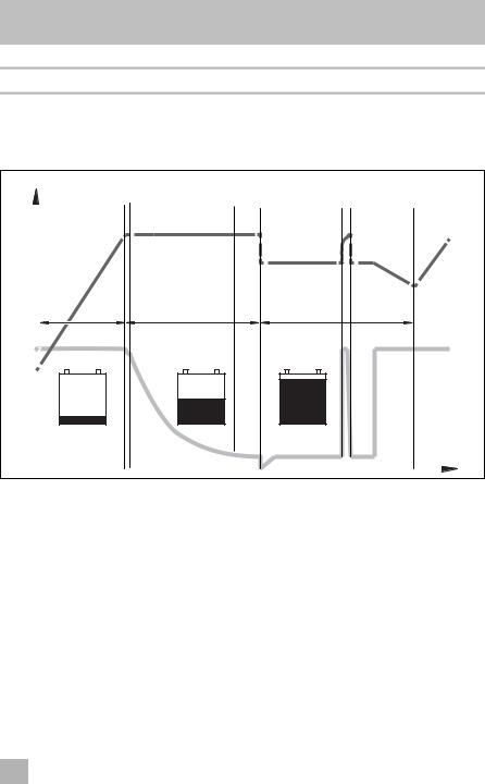
6.3Battery charging function
The charging characteristics are referred to as modified IU0U characteristics.
U/V |
1 |
2 |
3 |
4 |
5 |
6 |
|
I/A |
|||||||
|
|
|
|
|
|
||
|
|
|
|
|
|
U |
|
|
I |
|
U0 |
|
|
U |
|
|
100 % |
|
|
|
|
I |
|
|
|
|
|
|
|
||
|
|
|
|
|
6 % |
|
|
|
|
|
|
|
|
t |
1: I phase (bulk)
At the beginning of the charging process, the flat battery is charged with a constant current (100 % charge current) until the battery voltage reaches the charging voltage. The charging current decreases when the battery has reached this charging level.
17
EN

Installing the device |
MCA1215 – MCA2440 |
2, 3, 4: U0 phase (absorption)
Now the three-stage absorption charging process (U0 phase) begins, where the duration depends on the battery. The voltage remains constant (U0). In the first
2 minutes, the charging of the battery is determined. Then the main charging phase begins when the battery is fully charged.
Once the battery is completely charged, or the charging current is below 6 % of the rated charging current for 15 minutes, the U0 phase has finished.
5: U phase (float)
After the U0 phase, the battery charger switches to conservation charging function (U phase).
If DC loads are connected, they are powered by the device. Only if the power required exceeds the capacity of the device is this surplus power provided by the battery. The battery is then discharged until the device re-enters the I phase and charges the battery.
6: 12-day conditioning
Every 12 days, the battery charger switches back to phase 1 for 85 min in order to revive the battery. This prevents any fatigue symptoms such as sulphation.
7Installing the device
When selecting the installation location, observe the following instructions:
•The device can be installed horizontally or vertically.
•Do not install the device
–In wet or damp environments
–In dusty environments
–In the vicinity of combustible materials
–In areas where there is a danger of explosions.
•The place of installation must be well ventilated. A ventilation system must be available for installations in small, enclosed spaces. The clearance around the device must be at least 25 cm.
•The air inlet on the underside and the air outlet on the back of the device must remain clear.
•For ambient temperatures higher than 40 °C (such as in engine or heating compartments, or direct sunlight), the heat from the device under load can lead to reduced output.
18
EN

MCA1215 – MCA2440 |
Installing the device |
•The device must be installed on a level and sufficiently sturdy surface.
•Do not install the device in the same area as the batteries.
•Do not install the device above batteries, because they can emit corrosive sulphur fumes that will damage the device.
ANOTICE!
Before drilling any holes, make sure that no electrical cables or other parts of the vehicle can be damaged by drilling, sawing and filing.
For installation and mounting you will need the following tools:
•Pen for marking
•Drill bit set
•Drill
•Screwdriver
To secure the device in place you will need:
•Machine bolts (M4) with washers and self-locking nuts or
•self-tapping screws or wood screws.
Fasten the device as follows:
Hold the device against the installation location.
Mark the fastening points.
Fasten the device with one screw through each hole in the holders.
19
EN

Connecting the device |
MCA1215 – MCA2440 |
8Connecting the device
8.1Connecting to battery and power supply
Connecting the battery
Observe the following instructions when connecting the battery:
!CAUTION!
•Avoid coming into contact with the battery fluid.
•Batteries with a cell short circuit may not be charged, as explosive gases may form due to overheating of the battery.
•Make sure the battery terminals are clean when connecting them.
•Make sure the plug connector is fitted securely.
•Select a connection cable with a sufficient cross-section (see chapter “Technical data” on page 31).
•Lay the cables in accordance with VDE°100 (Germany).
•Connect the negative cable directly to the negative terminal of the battery, and not to the chassis of a vehicle or boat.
•Use the following cable colours:
–Red: positive connection
–Black: negative connection
•Do not reverse the polarity. Reversing the polarity can cause damage to the device.
Lay the positive cable from the battery charger to the positive terminal of the battery and connect it.
Lay the negative cable from the battery charger to the negative terminal of the battery and connect it.
Connecting the 230 V power supply
Plug the 230 V connection cable included in the delivery into the MCA battery charger‘s “AC INPUT” socket.
Connect the device with the he 230 V connection cable to a 230 V socket which is protected by a residual current circuit breaker.
20
EN
MCA1215 – MCA2440 |
Connecting the device |
8.2Charge versions
fig. 3, page 5
Battery sensor |
Perfect Control |
MCA-HS1 (IBS) |
MPC01 |
(12 V only) |
(12 V only) |
– |
– |
|
|
|
– |
|
|
|
|
– without; with
Charging the battery
fig. 4, page 5
Remote control |
Temperature sensor |
MCA-RC1 |
MCA-TS1 or |
|
Battery sensor |
|
MCA-HS1 (IBS) |
|
(12 V only) |
|
|
– |
– |
|
|
|
– |
|
|
– |
|
|
|
|
|
|
|
Connect the battery to the “DC OUTPUT” socket of the MCA battery charger.
• Make sure the polarity of the connections is correct.
Charging the starter battery (MCA1215, 1225, 1235 only)
Connect the starter battery to the “ESB” socket of the MCA battery charger.
• Make sure the polarity of the connections is correct.
Charging using the temperature sensor MCA-TS1 (accessory)
Connect the temperature sensor to the TEMP/LIN connection.
The charging voltage is adjusted according to the temperature measured.
Charging using the IBS battery sensor MCA-HS1 (accessory) (12 V only)
Connect the battery sensor to the TEMP/LIN connection.
The battery sensor transmits the battery temperature and the battery voltage to the charger via the LIN communication port. The charging voltage is regulated according to the temperature. Any potential loss of voltage in the connecting cables is also compensated.
21
EN

Connecting the device |
MCA1215 – MCA2440 |
Charging using the battery management system PerfectControl MPC01 (accessory) (12 V only)
Set the DIP switches 1 to 3 on the MCA battery charger to “ON” (chapter “Setting the DIP switches” on page 24).
You can find detailed information in the operating manual for MPC01.
Charging using the remote control MCA-RC1 (accessory)
INOTE
The length of the RJ-11 cable may not exceed 7 m.
Insert one end of the RJ-11 cable into the socket (fig. 0 3, page 7) of the MCA-RC1.
Insert the other end of the RJ-11 cable into the TEMP/LIN1 socket on the MCA battery charger.
8.3Wiring diagrams
Example of a wiring diagram, 12 V: see fig. 5, page 6.
No. in
Explanation/function
fig. 5, page 6
1MCA charger
2Consumer
3PerfectControl MPC01
412 V battery sensor IBS
512 V battery
6Fuse
7Starter battery
Example of a wiring diagram, 24 V: see fig. 6, page 6.
No. in
Explanation/function
fig. 6, page 6
1MCA charger
212 V battery
3Starter battery
22
EN

MCA1215 – MCA2440 |
Connecting the device |
8.4Pin assignment
The pins for the TEMP/LIN1 bus socket are assigned as follows:
Pin in
Allocation
fig. 7, page 6
1R_VCC
2GND
3TEMP
4BAT –
5LIN BUS DATA I/O
6BAT +
The pins for the LIN2 bus socket are assigned as follows:
Pin in
Allocation
fig. 7, page 6
1R_VCC
2BAT –
3NC
4BAT –
5LIN BUS DATA I/O
6BAT +
The pins for the CN2 socket (alarm signal and fan control) are assigned as follows:
Pin in |
Allocation |
|
fig. 8, page 6 |
||
|
||
|
|
|
1 |
NC (Normally Closed): normally closed contact |
|
|
|
|
2 |
NO (Normally Open): normally open contact |
|
|
|
|
3 |
COM (Common): common contact |
|
|
|
|
4 |
Sleep mode control |
|
|
|
|
5 |
GND |
|
|
|
|
4 – 5 bridged |
Sleep mode on |
|
|
|
|
4 – 5 open |
Sleep mode off |
|
|
|
23
EN

Connecting the device |
MCA1215 – MCA2440 |
The pins for the ESB socket (starter battery connection) are assigned as follows:
Pin in
Allocation
fig. 9, page 6
+VCC
–GND
8.5Setting the DIP switches
You can adjust the device using the DIP switch.
S1 is used to set the voltage at which the device switches over from the I phase (bulk) to the U0 phase (absorption) (also see chapter “Battery charging function” on page 17). S3 must be set to “OFF”.
S2 is used to set the retention voltage. S3 must be set to “OFF”.
When a battery sensor is connected, the output voltages is adapted to the temperature for these two functions:
•MCA 12xx: –20 mV/°C
•MCA 24xx: –40 mV/°C
S3 activates the power mode when either S1 or S2, or both, are set to “Off”. In power mode, the short circuit, overvoltage and overheating protection are controlled by the internal sensor.
When S1, S2 and S3 are set to “On”, then the function control by external devices is activated. Among others the type of battery and the charging voltage are set using the external device in this mode.
S4 regulates the fan function. When S4 is set to “On”, then the fan is switched to sleep mode (noise-reduced mode). When S4 is set to “Off”, then the fan is not regulated.
24
EN

MCA1215 – MCA2440 |
Connecting the device |
Use the DIP switches (fig. a page 7) to set the required functions and values:
– To set the switchover voltage:
Switch 1 |
Switch 3 |
Switchover voltage |
|
|
|
ON |
OFF |
14.4 V / 28.8 V |
|
|
|
OFF |
OFF |
14.7 V / 29.4 V |
|
|
|
– To set the retention voltage:
Switch 2 |
Switch 3 |
Retention voltage |
|
|
|
ON |
OFF |
13.5 V / 27.0 V |
|
|
|
OFF |
OFF |
13.8 V / 27.6 V |
|
|
|
– To set the power mode:
Switch 1 |
Switch 2 |
Switch 3 |
Constant voltage |
|
|
|
|
MCA12.. |
MCA24.. |
|
|
|
|
|
OFF |
OFF |
ON |
13.2 V |
26.4 V |
|
|
|
|
|
OFF |
ON |
ON |
13.8 V |
27.6 V |
|
|
|
|
|
ON |
OFF |
ON |
14.4 V |
28.8 V |
|
|
|
|
|
–Enabling the control for external devices (such as MPC01, does not apply to MCA-RC1):
Switch 1 |
Switch 2 |
Switch 3 |
|
|
|
ON |
ON |
ON |
|
|
|
– To activate sleep mode:
Switch 4
ON
25
EN

Using the device |
MCA1215 – MCA2440 |
9Using the device
Set the On/off switch to “On”.
To switch off the device set the On/off switch to “On”.
Depending on the charging condition of the battery, the battery charger starts charging or supplies a retention voltage.
The “Status” LED (fig. 1 5, page 3) displays the operating status (see following table and chapter “Battery charging function” on page 17).
Display |
Meaning |
|
|
Orange, quickly flashing |
Phase 1 |
|
|
Orange, slowly flashing |
Phase 2 |
|
|
Orange, constantly lit |
Phase 3 |
|
|
Green, constantly lit |
Phase 4 |
|
|
Green, slowly flashing |
Phase 5 |
|
|
Red, constantly lit |
Short circuit or defective fuse |
|
|
Red, quickly flashing |
Battery or battery charger is overheating |
|
|
Red, slowly flashing |
Battery undervoltage or overload |
|
|
Red, 1x Quick flash, 2x Long flash |
Fan fault |
|
|
Red, slow double flash |
Fault at the starter battery connection |
|
|
INOTE
In the event of a fault (the Status LED is red), refer to chapter “Troubleshooting” on page 29).
26
EN

MCA1215 – MCA2440 |
Using the device |
When you have connected the remote control MCA-RC1 (accessory)
Activate or deactivate sleep mode (noise reduced mode) using the “Sleep Mode” button (fig. 0 2, page 7).
The fan is not regulated in sleep mode.
The LED (fig. 0 1, page 7) on the MCA-RC1 indicates the operating status (see following table).
Mode |
Display |
Meaning |
|
|
|
Sleep mode activated |
Orange, constantly lit |
Phase 1 to 5 |
|
|
|
Sleep mode |
Green, slowly |
Phase 1 to 4 |
deactivated |
flashing |
|
|
|
|
|
Green, constantly lit |
Phase 5 |
|
|
|
Fault |
Red, constantly lit |
Short circuit or defective fuse |
|
|
|
|
Red, quickly flashing |
Battery or battery charger is overheating |
|
|
|
|
Red, slowly flashing |
Battery undervoltage or overload |
|
|
|
|
Red, double flash |
Fan fault |
|
|
|
|
Red, slow double |
Fault at the starter battery connection |
|
flash |
|
|
|
|
INOTE
In the event of a fault (the Status LED is red), refer to chapter “Troubleshooting” on page 29).
27
EN

Maintaining and cleaning the device |
MCA1215 – MCA2440 |
10 Maintaining and cleaning the device
ANOTICE!
Do not use any sharp or hard objects for cleaning since they may damage the device.
Disconnect the device from the 230 V power supply.
Disconnect the device from the battery.
Prevent the device from being switched on.
Occasionally clean the device with a damp cloth.
Regularly clean the vents.
Check the electrical wiring at least once a year.
Repair any defects such as loose connections or burnt cables.
28
EN

MCA1215 – MCA2440 |
Troubleshooting |
11 Troubleshooting
The “Status” LED (fig. 1 5, page 3) displays the fault:
LED display |
Cause |
Red, slowly flashing |
Battery undervoltage or bat- |
|
tery overload |
Remedy
Check the battery.
Switch the battery charger off and on again.
|
Defective battery |
Replace the battery. |
|
|
|
Red, slowly flashing |
Overheating |
Improve the ventilation of the bat- |
|
|
tery charger or battery. |
|
|
Make sure that no ventilation open- |
|
|
ings are covered. |
|
|
If necessary, reduce the ambient |
|
|
temperature. |
|
|
|
Red, permanently lit |
Short circuit or reversed |
Connect the battery charger with |
|
polarity |
the correct polarity. |
|
|
Rectify the short circuit. |
|
|
Check if the fuse has triggered and |
|
|
replace it if necessary. |
|
|
|
Red, double flash |
Fan fault |
Check the fan for dirt or damage. |
|
|
|
Red, slow double |
Fault at the starter battery |
Check the starter battery connec- |
flash |
connection |
tion for a short circuit. |
|
|
|
INOTE
If you have detailed questions on the battery specifications, please contact the battery manufacturer.
29
EN

Warranty |
MCA1215 – MCA2440 |
12 Warranty
The statutory warranty period applies. If the product is defective, please contact the manufacturer's branch in your country (see the back of the instruction manual for the addresses) or your retailer.
For repair and guarantee processing, please include the following documents when you send in the device:
•A copy of the receipt with purchasing date
•A reason for the claim or description of the fault
13 Disposal
Place the packaging material in the appropriate recycling waste bins wherever possible.
MIf you wish to finally dispose of the product, ask your local recycling centre or specialist dealer for details about how to do this in accordance with the applicable disposal regulations.
30
EN
 Loading...