


RM2852
INST ALLATION AND
OPERATING INSTRUCTIONS
REFRIGERATOR FOR LP-GAS AND ELECTRIC OPERATION
RM2652 RM2852
USA Corporate Office CANADA
Service Office 2320 Industrial Parkway Elkhart, IN 46515 Dometic Distribution Inc.
Dometic Corporation 866 Langs Drive
2320 Industrial Parkway Cambridge, Ontario
Elkhart, IN 46515 For Service Center Assistance N3H 2N7 Canada
Phone: 574-294-251 1 Call: 800-544-4881 Phone: 519-653-4390
822701206 MO-FO 0327 (French 3309599.003)
®
®
Contents:
Page
Installation 4
Operating Instructions 8
Maintenance & Service 12
FOR YOUR SAFETY
If you smell gas:
1. Open windows.
2. Don’t touch electrical switches.
3. Extinguish any open flame.
4. Immediately call your gas supplier .
FOR YOUR SAFETY
Do not store or use gasoline or other
flammable vapors and liquids in the
vicinity of this or any other appliance.
W ARNING: Improper installation,
adjustment, alteration, service or
maintenance can cause injury or
property damage. Refer to this
manual. For assistance or additional
information consult a qualified
installer, service agency or the gas
supplier.
Pour votre sécurité
Si vous sentez une odeur de gaz:
1. Ouvrez les fenêtres.
2. Ne touchez à aucun interrupteur.
3. Éteignez toute flamme nue.
4. Avertissez immédiatement votre fournis-
seur de gaz.
Pour votre sécurité
Ne pas entreposer ni utiliser de l’essence ni
d’autres vapeurs ou liquides inflammables à
proximité de cet appareil ou de tout autre
appareil.
Avertissement: Une installation, un réglage,
une modification, une réparation ou un
entretien non conforme aux normes peut
entraîner des blessures ou des dommages
matériels. Lisez attentivement le mode d’em-
ploi fourni avec l’appareil. Pour obtenir de
l’aide ou des renseignements supplémentai-
res, consultez un installateur ou un service
d’entretien qualifié ou le fournisseur de gaz.

3
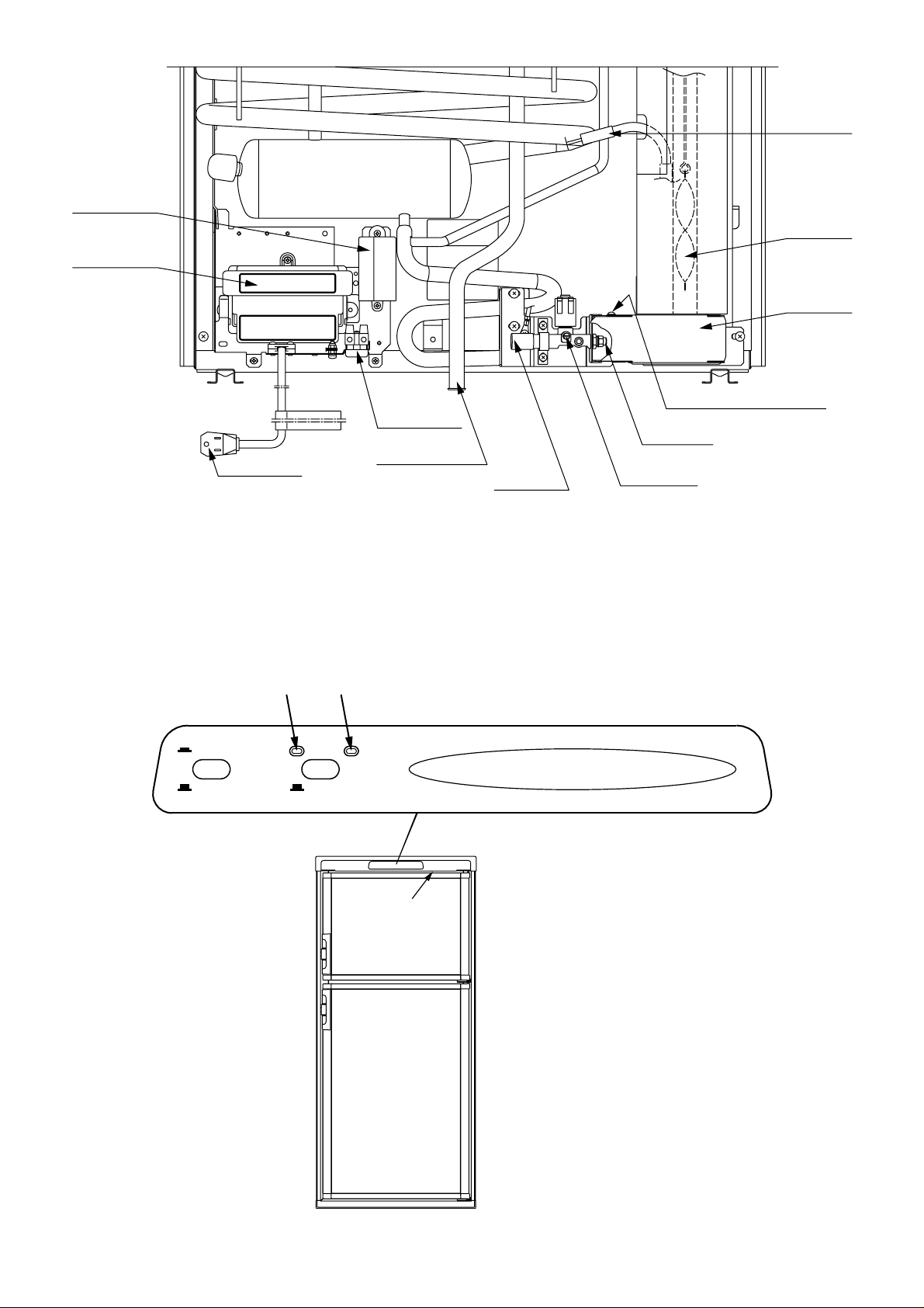
Refrigerator control panel
FIG. 2
CHECK
GAS
AUTO
ON
OFF
AUTOMATIC REFRIGERATOR TEMPERATURE CONTROL
12
AB
C
LEGEND
1. Main Power Button ON/OFF
2. AUT O/GAS Mode Selector Button
A. AUT O Mode Indicator Lamp
B. CHECK Indicator Lamp
(GAS Mode Only)
C. Climate Control Switch
12V DC
Cover,
Reigniter
Power module
cover
FIG. 1
Flexible cord
12 volt
Terminal block
Drain water hose
Inlet fitting
Manual gas
shutoff valve
Burner jet
Screw for protection cover
Protection
cover
Flue baffle
Heater
4
INSTALLATION
GENERAL INSTRUCTION
This appliance is designed for storage of foods and
storage of frozen foods and making ice.
This appliance is certified under the latest edition of
ANSI Z21.19•CSA 1.4 Refrigerators using gas fuel.
The installation must conform with local codes, or in
absence of local codes, the following standards as ap-
plicable.
In the U.S. the installation must conform with:
1. National Fuel Gas Code, ANSI Z223.1/NFPA 54
(latest edition).
2. Recreational Vehicles Code, ANSI A119.2 (latest
edition)
3. Manufactured Home Construction and Safety
St andard, T itle 24 CFR, Part 3280.
If an external electrical source is utilized, the refrigera-
tor, when inst alled, must be electrically grounded in ac-
cordance with local codes or, in the absence of local
codes, the National Electrical Code, ANSI/NFP A 70 - (lat-
est edition).
In CANADA, the installation must conform with:
1. Natural Gas and Propane Installation Code,
CSA B149.1
2. CSA Z240 R V Series, Recreational Vehicles.
3. Current CSA Z240.4, Gas-equipped Recreational
Vehicles and Mobile Housing.
If an external electrical source is utilized, the refrigera-
tor, when inst alled, must be electrically grounded in ac-
cordance with local codes or, in the absence of local
codes, the Canadian Electrical Code, CSA C22.1, Part s
I and II - (latest edition).
VENTILATION
The installation shall be made in such a manner as to
separate the combustion system from the living space
of the mobile home or recreational vehicle. Openings
for air supply or for venting of combustion products shall
have a minimum dimension of not less than 1/4 inch.
Proper installation requires one lower fresh air intake
and one upper exhaust vent. The ventilation kits shown
in this instruction manual have been certified for use
with the refrigerator models listed in the Table.
For “Certified Vent System Kit s” see page 15.
The ventilation kits must be installed and used without
modification. An opening toward the outside at floor level
in the refrigerator compartment must be provided for
ventilation of heavier-than-air fuel gases. The lower vent
of the recommended kits is provided with proper size
openings. The flow of combustion and ventilating air must
not be obstructed.
The lower side vent is fitted with a panel, which provides
an adequate access opening for ready serviceability of
the burner and control manifold of the refrigerator. This
should be centered on the back of the refrigerator.
GAS CONNECTION
Hook up to the gas supply line is accomplished at the
manual gas valve, which is furnished with a 3/8" SAE
(UNF 5/8" -18) male flare connection. All completed con-
nections should be checked for leaks with soapy water.
DO NOT use a flame to check for gas leaks.
The gas supply system must incorporate a pressure regu-
lator to maintain a supply pressure of not more than 11
inches water column.
When testing the gas supply system at test pressures in
excess of 1/2 psi, the refrigerator and its individual shutoff
valve must be disconnected from the gas supply piping
system.
When testing the gas supply system at pressures less
than or equal to 1/2 psi, the appliance must be isolated
from the gas supply piping system by closing its indi-
vidual manual shutoff valve.
In case detailed instructions on the installation and con-
nection to the gas supply are required, contact your
dealer or distributor.
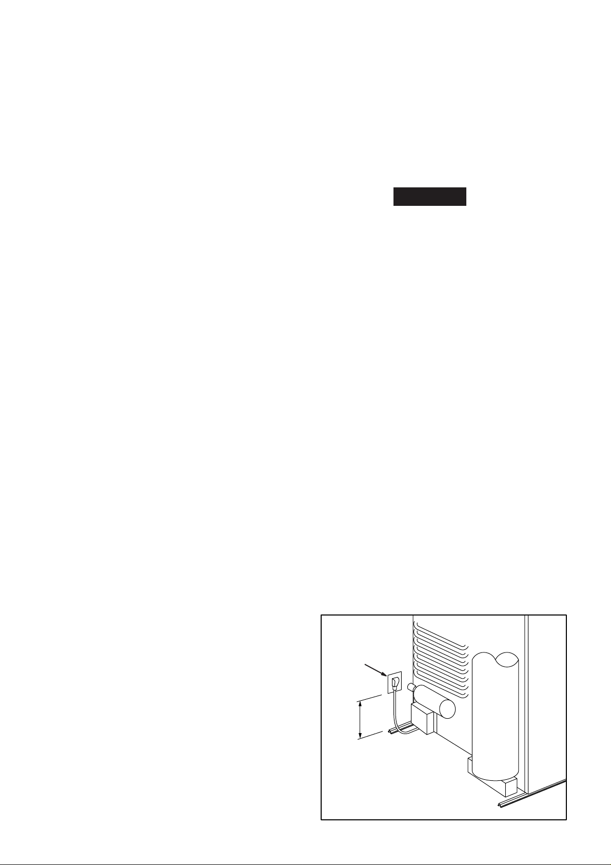
ELECTRICAL CONNECTION
120 Volts AC Connection
The refrigerator is equipped with a three-prong (ground-
ing) plug for your protection against shock hazards and
should be plugged directly into a properly grounded
three-prong receptacle. DO NOT cut or remove the
grounding prong from this plug. The free length of the
cord is 2 feet and therefore recommended that the re-
ceptacle be located to the left side of the refrigerator
(viewed from the rear) and approximately 6 inches from
the floor (see FIG. 3). This allows easy access through
the vent door. The cord should be routed to avoid direct
contact with the burner cover, flue cover or any other
components that could damage the cord insulation.
! WARNING
6”
120 Volt AC
receptacle
FIG. 3
5
12 Volts DC Connection
This refrigerator model is not designed for 12 volt DC
operation of the cooling system; however, a continuous
12 volt DC must be supplied to the refrigerator to oper-
ate the controls. Use a minimum of a 14 gauge wire
between the battery and refrigerator to supply the con-
trol voltage.
The connection is made to the positive (+) and negative (-)
terminals located at the rear of the refrigerator. (See
FIG. 1).
Correct polarity must be observed when connecting to
the DC supply .
Do not use the chassis or vehicle frame as one of the
conductors. Connect two wires at the refrigerator and
route to the DC supply .
INSTALLING REFRIGERATOR IN
ENCLOSURE
NOTE: DO NOT install the appliance directly on
carpeting. Carpeting must be removed or
protected by a metal or wood panel beneath
the appliance, which extends at least full
width and depth of the appliance.
NOTE: A wood strip must be in place across the upper
opening of the enclosure. The top frame of the refrigera-
tor will be anchored to the wood strip with screws.
See FIG. 10.
The refrigerator must be installed in a substantial enclo-
sure and must be level. When installing the refrigerator
in the enclosure, all areas within the recess in which the
refrigerator is installed must be sealed.
Make sure that there is a complete seal between the
front frame of the refrigerator and the top, sides and
bottom of the enclosure. A length of sealing strip is ap-
plied to the rear surface of the front frame for this pur-
pose, see FIG. 4.
The sealing should provide a complete isolation of the
appliance’s combustion system from the vehicle interior .
NOTE: Be careful not to damage the sealing strip when
the refrigerator is put in place.
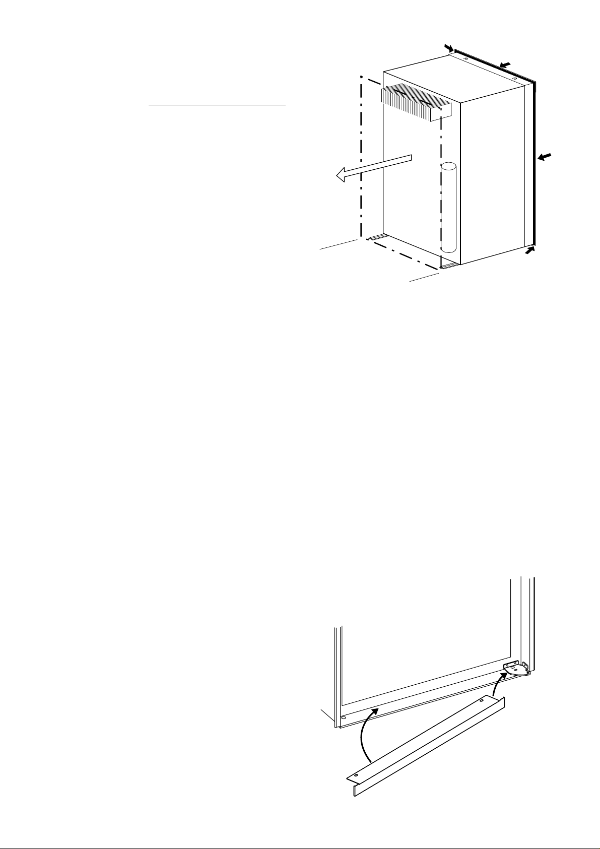
Securing the Refrigerator
After the refrigerator is put in place, (ensuring a com-
bustion seal at the front frame), the refrigerator is to be
secured in the enclosure with six screws (not included).
The screws have to be installed in the following order:
STEP 1: T wo screws installed through the front base,
which includes the lower front strip installation.
The refrigerator is provided with a lower front strip
(shipped as a loose part). The front strip is to be attached
after the refrigerator is set into the cutout opening.
1. Install the lower front strip by sliding it under the
bottom hinge plate, as shown in FIG. 5. The hinge
plate can be on the right or left side depending on
the door swing.
2
1
FIG. 5
FIG. 4
6
2. Once the lower front strip is slipped under the
hinge, the part is possible to swing into place as
shown in FIG. 6.
3. Secure the refrigerator and the lower front strip with
two screws:
One screw through the hinge, and on the opposite
side one screw through the lower front strip. (FIG. 6).
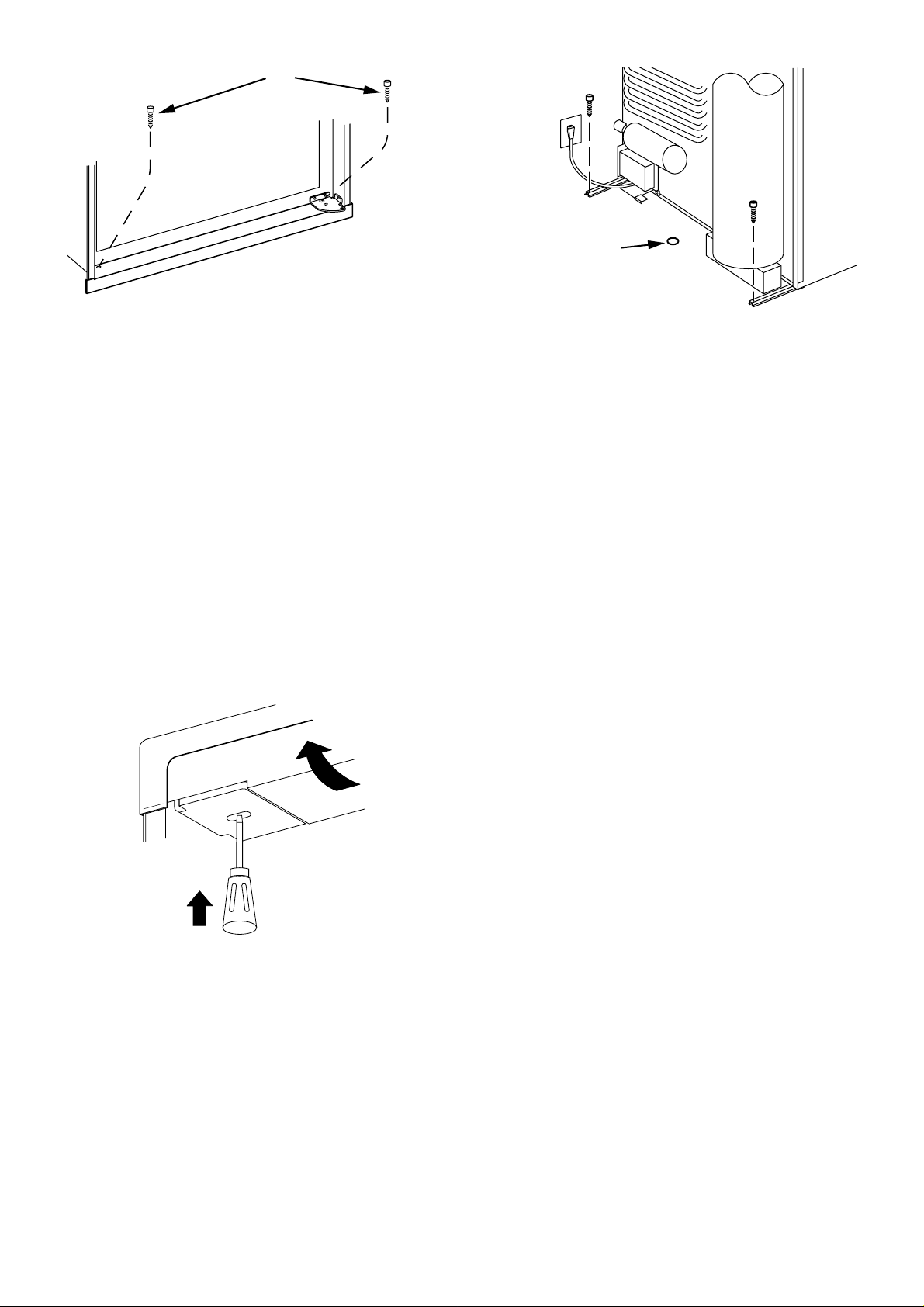
STEP 2: Two screws installed in the top frame.
The top decoration panel must be removed from the re-
frigerator before the screws can be installed.
Open the door and gently push the tabs out of the hole
in the hinge with a flat blade screwdriver, (both sides).
See FIG. 7.
Carefully tilt the top decoration panel and lift up to re-
move from top frame. Be careful not to damage the cir-
cuit board and wires.
Any space between the counter , storage area or ceiling
and top of the refrigerator greater than 1-1/2 inches
should be blocked. The heat produced at the rear of the
refrigerator will become trapped in this space, making
the top of the refrigerator hot and reduce the efficiency
of the refrigerator.
Drain water hose
A hole must be drilled through flooring see FIG. 8.
The installer MUST make sure that the hose does not
kink when run through the floor. Seal around the hose
that goes through the drilled hole. If a longer hose than
supplied is required to get the water to drain outside of
the vehicle, the installer will have to supply the extra
length of hose.
TESTING LP GAS SAFETY SHUTOFF
The gas safety shutoff must be tested after the re-
frigerator is connected to the LP gas supply .
To test the gas safety shutoff, proceed as follows:
1. Start the refrigerator according to the instructions
without connecting to 120 volts AC.
2. Check that the gas flame is lit. In AUT O mode the
AUTO mode indicator lamp (A) is on.
3. Close the manual gas shutoff valve at the back of
the refrigerator. (See FIG. 1).
4. Wait for one minute. The CHECK indicator lamp (B)
should be on, and the flame extinguished.
5. Remove protection cover (see FIG. 1) and open the
manual gas shutoff valve. Do not change any button
positions on the control panel. Apply a non-corrosive
commercial bubble solution to the burner jet orifice.
6. No bubbles should appear at the opening of the
burner jet orifice. The presence of bubbles indi-
cates a defective gas safety shutoff, and service is
required.
7. If no bubbles were present at the burner jet orifice,
it should be rinsed with fresh water. Be careful not
to damage the burner jet orifice. Replace cover and
press the main power ON/OFF button (1) OFF and
back ON. Normal operation of the burner should
return. Allow the burner to operate for a minimum
of 5 minutes.
3
FIG. 6
FIG. 7
1
2
Install the two screws in the top frame, the holes are
accessible from underneath.
Seal the opening for the screws with aluminum tape.
Replace the top decoration panel. Be careful not to pinch
the wires behind the panel.
Make sure the tabs snap back into the holes in the hinge
plate.
STEP 3: Two screws installed in the rear base.
See FIG. 8
Failure to follow the sequence in securing the refrigerator
in the enclosure can cause leakage between the frame
and cabinet.
FIG. 8
Hole for drain water hose
 Loading...