


DRIVING SUPPORT MAGICCOMFORT
MSH300, MSH301
EN Retrofit insert seat heater
Installation and Operating Manual . . . . . . . . 9
|
Nachrüstbare Einbau-Sitzheizung |
|
DE |
|
|
|
Montageund Bedienungsanleitung . . . . .20 |
|
|
Calefacción del asiento como |
|
FR |
|
|
|
aditamento adicional |
|
|
Instructions de montage |
|
|
et de service . . . . . . . . . . . . . . . . . . . . . . . . . |
31 |
|
Chauffage de siège, montage |
|
ES |
|
|
|
ultérieur |
|
|
Instrucciones de montaje y de uso . . . . . . .43 |
|
|
Aquecimento de banco para |
|
PT |
|
|
|
retromontagem |
|
|
Instruções de montagem e manual de |
|
|
instruções . . . . . . . . . . . . . . . . . . . . . . . . . . . |
55 |
|
Riscaldamento sedili addizionale |
|
IT |
|
|
|
Istruzioni di montaggio e d’uso . . . . . . . . . 67 |
|
|
In te bouwen stoelverwarming |
|
NL |
|
|
DA
SV
NO
FI
RU
PL
SK
CS
HU
Sædevarme til eftermontering
Monteringsog betjeningsvejledning. . . . 90
Stolvärmeanordning för montering i efterhand
Monteringsoch bruksanvisning . . . . . . . 101
Ettermonterbar setevarmer
Monteringsog bruksanvisning . . . . . . . . 112
Jälkikäteen asennettava istuinlämmitys
Asennusja käyttöohje . . . . . . . . . . . . . . . 123
Встраиваемый комплект обогрева сидений
Инструкция по монтажу и эксплуатации 134
System podgrzewania foteli do montażu
Instrukcja montażu i obsługi. . . . . . . . . . . 145
Vyhrievanie sedadla určené pre dodatočnú montáž
Návod na montáž a uvedenie
do prevádzky. . . . . . . . . . . . . . . . . . . . . . . 157
Vestavné vyhřívání sedadla
Návod k montáži a obsluze . . . . . . . . . . . 168
Utólag beszerelhető ülésfűtés
Szerelési és használati útmutató . . . . . . . 179
Montagehandleiding en
gebruiksaanwijzing . . . . . . . . . . . . . . . . . . .79
MSH300, MSH301 |
|
|
|
1 |
1 |
2 |
3 |
|
|||
4 |
|
5 |
6 |
7 |
8 |
|
9 |
10 |
|
11 |
12 |
13 |
|
14 |
15 |
|
|
|
3 |
MSH300, MSH301
2 |
3 |
4 |
2 |
1 5
3 |
4 |
|
1 |
|
2 |
|
|
|
|
5 |
6 |
|
|
|
|
– |
|
|
|
30 |
cm |
|
|
35 |
|
|
|
|
|
4

MSH300, MSH301 |
|
|
7 |
8 |
9 |
0 |
a |
b |
c |
d |
de |
f |
|
g |
5
MSH300, MSH301
h
MSH300
|
bk |
|
|
bu |
|
|
|
|
|
|
5 A |
|
|
bk |
15 A |
|
|
|
|
bk |
bu |
|
(31) |
R |
L |
|
|
og
rd
+12 V (15)
+12 V (30)
6
MSH300, MSH301
i
MSH301
bu |
|
|
|
|
|
|
5 A |
|
|
bk |
15 A |
|
|
|
|
R |
bu |
|
(31) |
L |
|
|
og
rd
+12 V (15)
+12 V (30)
|
EN |
DE |
FR |
ES |
PT |
IT |
NL |
DA |
SV |
|
|
|
|
|
|
|
|
|
|
bu |
Blue |
Blau |
Bleu |
Azul |
Azul |
Blu |
Blauw |
Blå |
Blå |
|
|
|
|
|
|
|
|
|
|
og |
Orange |
Orange |
Orange |
Naranja |
Cor de laranja |
Arancione |
Oranje |
Orange |
Orange |
|
|
|
|
|
|
|
|
|
|
rd |
Red |
Rot |
Rouge |
Rojo |
Vermelho |
Rosso |
Rood |
Rød |
Röd |
|
|
|
|
|
|
|
|
|
|
bk |
Black |
Schwarz |
Noir |
Negro |
Preto |
Nero |
Zwart |
Sort |
Svart |
|
|
|
|
|
|
|
|
|
|
|
NO |
FI |
RU |
PL |
SK |
CS |
HU |
|
|
|
|
|
|
|
|
bu |
Blå |
Sininen |
Синий |
Niebieski |
Modrá |
Modrá |
Kék |
|
|
|
|
|
|
|
|
og |
Oransje |
Oranssi |
Оранжевый |
Pomarańczowy |
Oranžová |
Oranžová |
Narancs |
|
|
|
|
|
|
|
|
rd |
Rød |
Punainen |
Красный |
Czerwony |
Červená |
Červená |
Piros |
|
|
|
|
|
|
|
|
bk |
Svart |
Musta |
Черный |
Czarny |
Čierna |
Černá |
Fekete |
|
|
|
|
|
|
|
|
7
MSH300, MSH301
j
k
20 mm
l
2 |
1 |
8

MSH300, MSH301
Please read this instruction manual carefully before installation and first use, and store it in a safe place. If you pass on the product to another person, hand over this instruction manual along with it.
Contents |
|
|
1 |
Explanation of symbols . . . . . . . . . . . . . . . . . . . . . . . . . . . . . . . . . . . . . . . . . . |
10 |
2 |
Safety and installation instructions . . . . . . . . . . . . . . . . . . . . . . . . . . . . . . . . . |
10 |
3 |
Scope of delivery . . . . . . . . . . . . . . . . . . . . . . . . . . . . . . . . . . . . . . . . . . . . . . |
13 |
4 |
Intended use . . . . . . . . . . . . . . . . . . . . . . . . . . . . . . . . . . . . . . . . . . . . . . . . . . |
13 |
5 |
Technical description . . . . . . . . . . . . . . . . . . . . . . . . . . . . . . . . . . . . . . . . . . . |
14 |
6 |
Installing the seat heater . . . . . . . . . . . . . . . . . . . . . . . . . . . . . . . . . . . . . . . . . |
14 |
7 |
Using the seat heater . . . . . . . . . . . . . . . . . . . . . . . . . . . . . . . . . . . . . . . . . . . |
18 |
8 |
Guarantee . . . . . . . . . . . . . . . . . . . . . . . . . . . . . . . . . . . . . . . . . . . . . . . . . . . . |
19 |
9 |
Disposal . . . . . . . . . . . . . . . . . . . . . . . . . . . . . . . . . . . . . . . . . . . . . . . . . . . . . . |
19 |
10 |
Technical data . . . . . . . . . . . . . . . . . . . . . . . . . . . . . . . . . . . . . . . . . . . . . . . . . |
19 |
EN |
9 |
|
|
|
|

Explanation of symbols |
MSH300, MSH301 |
1Explanation of symbols
!WARNING!
Safety instruction: Failure to observe this instruction can cause fatal or serious injury.
ANOTICE!
Failure to observe this instruction can cause material damage and impair the function of the product.
INOTE
Supplementary information for operating the product.
2Safety and installation instructions
Please observe the prescribed safety instructions and stipulations from the vehicle manufacturer and service workshops.
The manufacturer accepts no liability for damage in the following cases:
•Faulty assembly or connection
•Damage to the product resulting from mechanical influences and excess voltage
•Alterations to the product without express permission from the manufacturer
•Use for purposes other than those described in the operating manual
ANOTICE!
To prevent the risk of short circuits, always disconnect the negative terminal of the vehicle's electrical system before working on it.
If the vehicle has an additional battery, its negative terminal should also be disconnected.
!WARNING!
Inadequate supply cable connections could result in short circuits, which could have as a consequence that:
•Cable fires occur
•The airbag is triggered
•Electronic control devices are damaged
•Electric functions fail (indicators, brake light, horn, ignition, lights)
10 |
EN |
|
MSH300, MSH301 |
Safety and installation instructions |
Please observe the following instructions:
•When working on the following cables, only use insulated cable lugs, plugs and flat push-on receptacles:
–30 (direct supply from positive battery terminal)
–15 (connected positive terminal, behind the battery)
–31 (return cable from the battery, earth)
Do not use terminal strips.
•The safest type of connection is to solder the ends of the cables together and then insulate them.
Only use insulated cable terminals, plugs and flat sockets for releasable connections. Do not use crimp terminals (cable connectors) or terminal strips.
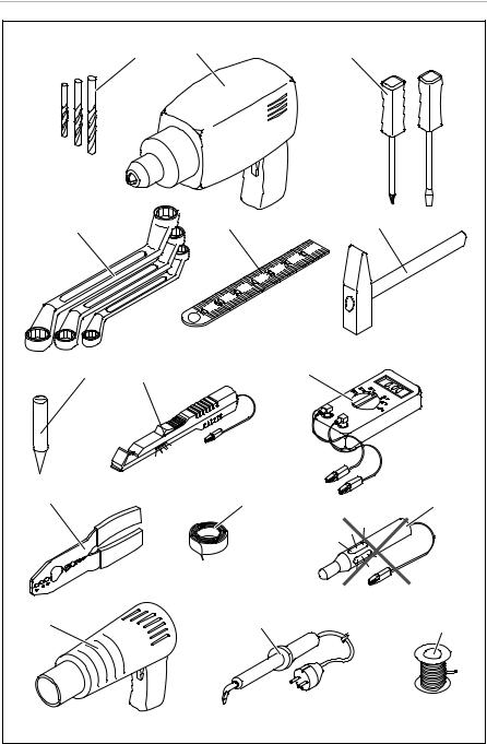
•Use a crimping tool (fig. 1 10, page 3) to connect the cables.
•When connecting to cable 31 (earth), screw the cable
–To the vehicle's earth bolt with a cable lug and a gear disc or
–To the sheet-metal bodywork with a cable lug and a self-tapping screw.
Ensure that there is a good earth connection.
If you disconnect the negative terminal of the battery, all data stored in the volatile memories will be lost.
•The following data must be set again, depending on the vehicle equipment options:
–Radio code
–Vehicle clock
–Timer
–On-board computer
–Seat position
You can find instructions for making these settings in the appropriate operating instructions.
Observe the following installation instructions:
•Secure the parts installed in the vehicle in such a way that they cannot become loose under any circumstances (sudden braking, accidents) and cause injuries to the occupants of the vehicle.
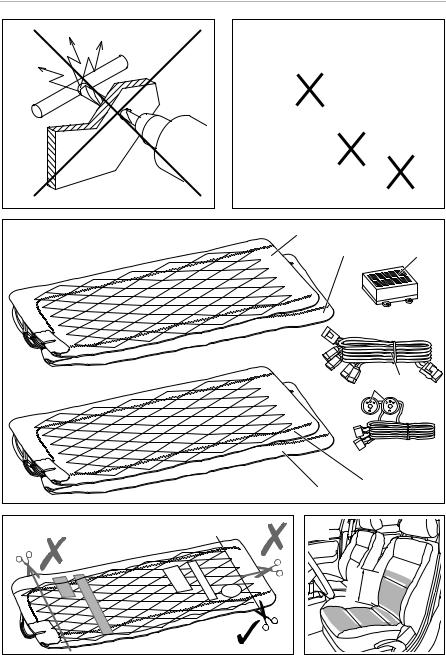
•To prevent damage, when drilling ensure that there is sufficient space on the other side for the drill head to come out (fig. 2, page 4).
•Deburr all drill holes and treat them with a rust-protection agent.
EN |
11 |
|
|
|
|

Safety and installation instructions |
MSH300, MSH301 |
Observe the following instructions when working with electrical parts:
•When testing the voltage in electrical cables, only use a diode test lamp (fig. 1 8, page 3) or a voltmeter (fig. 1 9, page 3).
Test lamps with an illuminant (fig. 1 12, page 3) take up voltages which are too high and which can damage the vehicle's electronic system.
•When making electrical connections (fig. 3, page 4), ensure that
–They are not kinked or twisted
–They do not rub on edges
–They are not laid in sharp-edged ducts without protection.
•Insulate all connections.
•Secure the cables against mechanical wear with cable binders or insulating tape, for example to existing cables.
Observe the following instructions when using the seat heater:
•Do not place any sharp or heavy objects on the seat, as the seat heater could otherwise be damaged.
•Persons with an impaired sensitivity to heat should only operate the seat heating on level 1.
•Do not place any heat insulating objects, such as blankets or coats, on the seat when the seat heater is switched on.
•The seat heater can be damaged by fluids spilt on the seat.
•Never switch the seat heater on when it is wet.
12 |
EN |
|

MSH300, MSH301 |
Scope of delivery |
3Scope of delivery
No. in
Quantity Designation Ref. no.
fig. 4, page 4
MSH300 MSH301
1 |
2 |
1 |
Seat surface heating element |
9101700038 |
2 |
2 |
1 |
Backrest heating element |
9101700039 |
|
|
|
|
|
3 |
2 |
1 |
Switch |
9101700041 |
|
|
|
|
|
4 |
1 |
1 |
Set of connecting cables |
9101700053 |
|
|
|
(black: right side |
|
|
|
|
blue: left side) |
|
|
|
|
|
|
5 |
1 |
1 |
Switchbox |
9101700051 |
|
|
|
|
|
– |
1 |
1 |
Drill template |
|
|
|
|
|
|
– |
12 |
6 |
Double-sided adhesive tape |
|
|
|
|
|
|
– |
12 |
6 |
Insulating material |
|
|
|
|
|
|
– |
1 |
1 |
Operating manual |
|
|
|
|
|
|
4Intended use
The MagicComfort seat heating MSH300 (ref. no. 9600000395) and
MSH301 (ref. no. 9600000396) are suitable for installation in the front vehicle seats of passenger vehicles, transporters and caravans.
ANOTICE!
For vehicles equipped with side airbags in the seat backrests, seat occupancy detection or child seat detection, observe the vehicle manufacturer's specifications.
EN |
13 |
|
|
|
|

Technical description |
MSH300, MSH301 |
5Technical description
The heating elements for the MagicComfort seat heating MSH300 and MSH301 can be installed in the driver’s seat and in the passenger seat.
The shape of the seat is not altered by the heating elements.
The seat heater is operated using a switch.
6Installing the seat heater
6.1Tools required (fig. 1, page 3)
For installation and assembly you will need the following tools:
•Drill bit set (1)
•Drill (2)
•Screwdriver (3)
•Set of ring or open-ended spanners (4)
•Measuring ruler (5)
•Hammer (6)
•Centre punch (7)
To make and test the electrical connection, the following tools are required:
•Diode test lamp (8) or voltmeter (9)
•Crimping tool (10)
•Insulating tape (11)
•Hot air blower (13)
•Soldering iron (14)
•Solder (15)
•Cable bushing sleeves (if necessary)
To fasten the cables you may require additional cable binders.
14 |
EN |
|

MSH300, MSH301 |
Installing the seat heater |
6.2Installing the seat heater
Removing the seat
Secure the vehicle against rolling away.
ANOTICE!
For vehicles with side air bags in the seat backrest, observe the manufacturer's instructions on removing the seats and the upholstery.
Check the suitability for installation using these installation instructions and the manufacturer's information.
Remove the fastening screws from the vehicle seat.
Lift the seat out of the vehicle.
Preparing the seat
Remove all plastic panelling from the seat to ensure the fastening of the cover fabric can be reached.
Separate the backrest from the seat (fig. 7, page 5 and fig. 8, page 5).
Open the seat cover on the seat surface.
The cover fabric is usually tucked into a seam on the frame with a wide cardboard strip or metal wire.
Remove the fasteners using a screwdriver and pliers (fig. 9, page 5 and fig. 0, page 5).
Remove any upholstery staples or cross braces (fig. a, page 5).
Open the cover of the backrest in the same way.
EN |
15 |
|
|
|
|

Installing the seat heater |
MSH300, MSH301 |
Preparing the heating elements
ANOTICE!
Insulate all the trimmed ends with the insulating material supplied to prevent a short circuit.
INOTE
•You can cut the heating elements to the required length and shorten the lengths of the two conductor paths.
•You can cut out a section of the heating element in the area of the
anchoring grooves on the seat or the backrest. Make sure the cut-out sections are only made between the two black seams (fig. 5, page 4).
•Do not cut the mat lengthways, otherwise it will not be heated in the area of the incision (fig. 5, page 4).
•The heating surface on the backrest only needs to extend approx.
30 – 35 cm above the seat, as the driver only leans against this area when sitting normally (fig. 6, page 4).
Place the heating elements on the seat and backrest.
If there are anchoring grooves in the seat or the backrest, mark these areas on the heating elements.
Mark the required lengths. Take into account the depth of the anchoring grooves, if present. The heating element is inserted in these anchoring grooves.
Trim the heating element to the required length.
Customise the cut-out sections as required.
Insulate all the trimmed ends with the insulating material.
16 |
EN |
|

MSH300, MSH301 |
Installing the seat heater |
Installing the heating element for the seat surface
Insert the heating element for the seat surface between the cover fabric and the foam core of the seat (fig. b, page 5).
If anchoring grooves are present, make sure that the cut-out sections are positioned over the anchoring grooves (fig. c, page 5) and place the heating elements in the anchoring grooves.
Fasten the heating element using double-sided adhesive tape to prevent it sliding on the foam core.
Ensure that no creases or kinks form.
Installing the heating element for the backrest
ANOTICE!
If the seats are equipped with side airbags, then there is a predetermined breaking point in the cover fabric. The seat cover must therefore not be pulled tightly or slip out of place.
Open the lower area of the backrest cover (fig. d, page 5).
Push the heating element into the gap between the seat cover and the seat cushion (fig. e, page 5).
Fasten the heating element using double-sided adhesive tape to prevent creases.
Installing the seat
Reassemble the backrest and seat.
Lift the seat into the vehicle.
Secure the vehicle seat with the fastening screws.
EN |
17 |
|
|
|
|

Using the seat heater |
MSH300, MSH301 |
Electrical connection
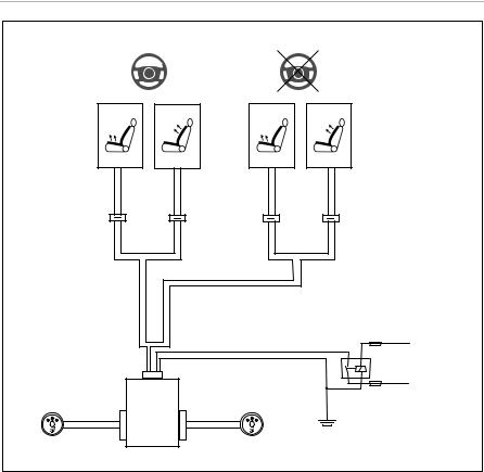
MSH300
The complete circuit diagram can be found in fig. h, page 6.
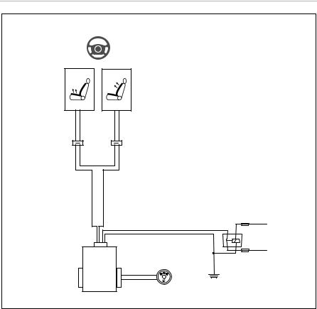
MSH301
The complete circuit diagram can be found in fig. i, page 7.
ANOTICE!
Ensure it has been securely fitted, particularly in the area of the seat rails.
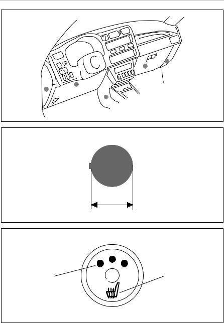
Attach the switchbox to a suitable location in the vicinity of the dashboard (fig. j, page 8).
Find a suitable place for installing the seat heater switch.
If possible, use the blanking plugs provided for this purpose.
Ensure that there is enough room behind the panel for the installation of the switch.
Mark the switch cut-out using the template provided (fig. k, page 8).
Cut out the marked area with an appropriate tool.
Install the switch into the cut-out (fig. f, page 5).
Install the ready-made wiring harness so that the cables cannot bend or fray (fig. g, page 5).
7Using the seat heater
INOTE
The seat heating logo (fig. l 1, page 8) also lights up when the seat heating is switched on.
Press the seat heater switch to turn on the seat heater:
–Press once: Level 3 (high heat output)
–Press twice: Level 2 (medium heat output)
–Press three times: Level 1 (low heat output)
One, two or three LEDs (fig. l 2, page 8) on the switch light up in red.
To switch the seat heating off: Press the switch until the LEDs (fig. l 2, page 8) on the switch go out.
18 |
EN |
|
MSH300, MSH301 |
Guarantee |
8Guarantee
The statutory warranty period applies. If the product is defective, please contact the manufacturer's branch in your country (see the back of the instruction manual for the addresses) or your retailer.
For repair and guarantee processing, please include the following documents when you send in the device:
•A copy of the receipt with purchasing date
•A reason for the claim or description of the fault
9Disposal
Place the packaging material in the appropriate recycling waste bins wherever possible.
MIf you wish to finally dispose of the product, ask your local recycling centre or specialist dealer for details about how to do this in accordance with the applicable disposal regulations.
10 |
Technical data |
|
|
|
|
|
|
|
|
MagicComfort MSH300 |
MagicComfort MSH301 |
|
|
|
|
Ref. no.: |
|
9600000395 |
9600000396 |
|
|
|
|
Operating voltage: |
12 Vg |
||
|
|
|
|
Power: |
|
adjustable to three levels, with 10 – 70 W per seat |
|
|
|
|
|
Max. power consumption: |
10 A |
5 A |
|
|
|
|
|
Dimensions: |
Seat element: 580 x 270 mm |
||
|
|
Backrest element: 580 x 270 mm |
|
|
|
|
|
EN |
19 |
|
|
|
|

MSH300, MSH301
Bitte lesen Sie diese Anleitung vor Einbau und Inbetriebnahme sorgfältig durch und bewahren Sie sie auf. Geben Sie sie im Falle einer Weitergabe des Produktes an den Nutzer weiter.
Inhaltsverzeichnis
1 Erklärung der Symbole . . . . . . . . . . . . . . . . . . . . . . . . . . . . . . . . . . . . . . . . . .21 2 Sicherheitsund Einbauhinweise . . . . . . . . . . . . . . . . . . . . . . . . . . . . . . . . . .21 3 Lieferumfang . . . . . . . . . . . . . . . . . . . . . . . . . . . . . . . . . . . . . . . . . . . . . . . . . 24 4 Bestimmungsgemäßer Gebrauch . . . . . . . . . . . . . . . . . . . . . . . . . . . . . . . . 24 5 Technische Beschreibung . . . . . . . . . . . . . . . . . . . . . . . . . . . . . . . . . . . . . . 24 6 Sitzheizung montieren . . . . . . . . . . . . . . . . . . . . . . . . . . . . . . . . . . . . . . . . . 25 7 Sitzheizung benutzen . . . . . . . . . . . . . . . . . . . . . . . . . . . . . . . . . . . . . . . . . . 29 8 Gewährleistung. . . . . . . . . . . . . . . . . . . . . . . . . . . . . . . . . . . . . . . . . . . . . . . 30 9 Entsorgung . . . . . . . . . . . . . . . . . . . . . . . . . . . . . . . . . . . . . . . . . . . . . . . . . . 30 10 Technische Daten . . . . . . . . . . . . . . . . . . . . . . . . . . . . . . . . . . . . . . . . . . . . . 30
20 |
DE |
|
MSH300, MSH301 |
Erklärung der Symbole |
1Erklärung der Symbole
!WARNUNG!
Sicherheitshinweis: Nichtbeachtung kann zu Tod oder schwerer Verletzung führen.
AACHTUNG!
Nichtbeachtung kann zu Materialschäden führen und die Funktion des Produktes beeinträchtigen.
IHINWEIS
Ergänzende Informationen zur Bedienung des Produktes.
2Sicherheitsund Einbauhinweise
Beachten Sie die vom Fahrzeughersteller und vom Kfz-Handwerk vorgeschriebenen Sicherheitshinweise und Auflagen!
Der Hersteller übernimmt in folgenden Fällen keine Haftung für Schäden:
•Montageoder Anschlussfehler
•Beschädigungen am Produkt durch mechanische Einflüsse und Überspannungen
•Veränderungen am Produkt ohne ausdrückliche Genehmigung vom Hersteller
•Verwendung für andere als die in der Anleitung beschriebenen Zwecke
AACHTUNG!
Klemmen Sie wegen der Kurzschlussgefahr vor Arbeiten an der Fahrzeugelektrik immer den Minuspol ab.
Bei Fahrzeugen mit Zusatzbatterie müssen Sie an dieser ebenfalls den Minuspol abklemmen.
!WARNUNG!
Unzureichende Leitungsverbindungen können zur Folge haben, dass durch Kurzschluss
•Kabelbrände entstehen,
•der Airbag ausgelöst wird,
•elektronische Steuerungseinrichtungen beschädigt werden,
•elektrische Funktionen ausfallen (Blinker, Bremslicht, Hupe, Zündung, Licht).
DE |
21 |
|
|
|
|

Sicherheitsund Einbauhinweise |
MSH300, MSH301 |
Beachten Sie deshalb folgende Hinweise:
•Verwenden Sie bei Arbeiten an den folgenden Leitungen nur isolierte Kabelschuhe, Stecker und Flachsteckhülsen:
–30 (Eingang von Batterie Plus direkt)
–15 (Geschaltetes Plus, hinter Batterie)
–31 (Rückleitung ab Batterie, Masse)
Verwenden Sie keine Lüsterklemmen.
•Die sicherste Verbindungsart ist, die Kabelenden miteinander zu verlöten und anschließend zu isolieren.
Verwenden Sie bei wiederlösbaren Verbindungen nur isolierte Kabelschuhe, Stecker und Flachsteckhülsen. Verwenden Sie keine Quetschverbinder (Leitungsverbinder) oder Lüsterklemmen.
•Verwenden Sie eine Krimpzange (Abb. 1 10, Seite 3) zum Verbinden der Kabel.
•Schrauben Sie das Kabel bei Anschlüssen an Leitung 31 (Masse)
–mit Kabelschuh und Zahnscheibe an eine fahrzeugeigene Masseschraube oder
–mit Kabelschuh und Blechschraube an das Karosserieblech.
Achten Sie auf eine gute Masseübertragung!
Beim Abklemmen des Minuspols der Batterie verlieren alle flüchtigen Speicher der Komfortelektronik ihre gespeicherten Daten.
•Folgende Daten müssen Sie je nach Fahrzeugausstattung neu einstellen:
–Radiocode
–Fahrzeuguhr
–Zeitschaltuhr
–Bordcomputer
–Sitzposition
Hinweise zur Einstellung finden Sie in der jeweiligen Bedienungsanleitung.
Beachten Sie folgende Hinweise bei der Montage:
•Befestigen Sie im Fahrzeug montierte Teile so, dass sie sich unter keinen Umständen (scharfes Abbremsen, Verkehrsunfall) lösen und zu Verletzungen der Fahrzeuginsassen führen können.
•Achten Sie beim Bohren auf ausreichenden Freiraum für den Bohreraustritt, um Schäden zu vermeiden (Abb. 2, Seite 4).
•Entgraten Sie jede Bohrung und behandeln Sie diese mit Rostschutzmittel.
22 |
DE |
|
MSH300, MSH301 |
Sicherheitsund Einbauhinweise |
Beachten Sie folgende Hinweise bei der Arbeit an elektrischen Teilen:
•Benutzen Sie zum Prüfen der Spannung in elektrischen Leitungen nur eine Diodenprüflampe (Abb. 1 8, Seite 3) oder ein Voltmeter (Abb. 1 9, Seite 3). Prüflampen mit einem Leuchtkörper (Abb. 1 12, Seite 3) nehmen zu hohe Ströme auf, wodurch die Fahrzeugelektronik beschädigt werden kann.
•Beachten Sie beim Verlegen der elektrischen Anschlüsse (Abb. 3, Seite 4), dass diese
–nicht geknickt oder verdreht werden,
–nicht an Kanten scheuern,
–nicht ohne Schutz durch scharfkantige Durchführungen verlegt werden.
•Isolieren Sie alle Verbindungen und Anschlüsse.
•Sichern Sie die Kabel gegen mechanische Beanspruchung durch Kabelbinder oder Isolierband, z. B. an vorhandenen Leitungen.
Beachten Sie folgende Hinweise bei der Verwendung der Sitzheizung:
•Legen Sie keine spitzen oder schweren Gegenstände auf den Sitz, da sonst die Sitzheizung beschädigt werden kann.
•Personen mit gestörtem Wärmeempfinden sollten die Sitzheizung nur in Stufe 1 betreiben.
•Legen Sie bei eingeschalteter Sitzheizung keine wärmedämmenden Gegenstände wie Decken oder Mäntel auf den Sitz.
•Die Sitzheizung kann durch verschüttete Flüssigkeiten auf dem Sitz beschädigt werden.
•Schalten Sie die Sitzheizung niemals im nassen Zustand ein.
DE |
23 |
|
|
|
|

Lieferumfang |
MSH300, MSH301 |
3Lieferumfang
Nr. in Abb. 4, |
Menge |
Bezeichnung |
Artikel-Nr. |
||
Seite 4 |
|||||
|
|
|
|
||
|
MSH300 |
MSH301 |
|
|
|
|
|
|
|
|
|
1 |
2 |
1 |
Heizelement Sitzfläche |
9101700038 |
|
|
|
|
|
|
|
2 |
2 |
1 |
Heizelement Lehne |
9101700039 |
|
|
|
|
|
|
|
3 |
2 |
1 |
Schalter |
9101700041 |
|
|
|
|
|
|
|
4 |
1 |
1 |
Anschlusskabelsatz |
9101700053 |
|
|
|
|
(schwarz: rechte Seite |
|
|
|
|
|
blau: linke Seite) |
|
|
|
|
|
|
|
|
5 |
1 |
1 |
Schaltbox |
9101700051 |
|
|
|
|
|
|
|
– |
1 |
1 |
Bohrschablone |
|
|
|
|
|
|
|
|
– |
12 |
6 |
Doppelseitiges Klebeband |
|
|
|
|
|
|
|
|
– |
12 |
6 |
Isoliermaterial |
|
|
|
|
|
|
|
|
– |
1 |
1 |
Bedienungsanleitung |
|
|
|
|
|
|
|
|
4Bestimmungsgemäßer Gebrauch
Die Sitzheizungen MagicComfort MSH300 (Art.-Nr. 9600000395) und
MSH301 (Art.-Nr. 9600000396) sind geeignet für den Einbau in die vorderen Fahrzeugsitze von Pkw, Transportern und Wohnmobilen.
AACHTUNG!
Bei Fahrzeugen mit Seitenairbags in den Sitzlehnen, Sitzbelegungserkennung oder Kindersitzerkennung sind die Herstellerangaben des Fahrzeugherstellers zu beachten.
5Technische Beschreibung
Die Heizelemente der Sitzheizungen MagicComfort MSH300 und MSH301 können in den Fahrersitz und den Beifahrersitz eingebaut werden.
Die Form des Sitzes wird durch die Heizelemente nicht verändert.
Die Bedienung der Sitzheizung erfolgt über einen Schalter.
24 |
DE |
|
MSH300, MSH301 |
Sitzheizung montieren |
6Sitzheizung montieren
6.1Benötigtes Werkzeug (Abb. 1, Seite 3)
Für Einbau und Montage benötigen Sie folgende Werkzeuge:
•Satz Bohrer (1)
•Bohrmaschine (2)
•Schraubendreher (3)
•Satz Ringoder Maulschlüssel (4)
•Maßstab (5)
•Hammer (6)
•Körner (7)
Für den elektrischen Anschluss und seine Überprüfung benötigen Sie folgende Hilfsmittel:
•Diodenprüflampe (8) oder Voltmeter (9)
•Krimpzange (10)
•Isolierband (11)
•Heißluftföhn (13)
•Lötkolben (14)
•Lötzinn (15)
•Ggf. Kabeldurchführungstüllen
Zur Befestigung der Kabel benötigen Sie ggf. noch weitere Kabelbinder.
DE |
25 |
|
|
|
|

Sitzheizung montieren |
MSH300, MSH301 |
6.2Sitzheizung montieren
Sitz demontieren
Sichern Sie das Fahrzeug gegen Wegrollen.
AACHTUNG!
Beachten Sie bei Fahrzeugen mit Seitenairbags in der Sitzlehne die Herstellerangaben zur Demontage der Sitze und Polster.
Prüfen Sie die Einbaubarkeit anhand dieser Einbauanleitung und der Herstellerinformation.
Entfernen Sie die Befestigungsschrauben des Fahrzeugsitzes.
Heben Sie den Sitz aus dem Fahrzeug.
Sitz vorbereiten
Entfernen Sie alle Kunststoffverkleidungen des Sitzes, um die Befestigungen des Bezugstoffes erreichen zu können.
Trennen Sie die Lehne von der Sitzfläche (Abb. 7, Seite 5 und Abb. 8, Seite 5).
Öffnen Sie den Sitzbezug der Sitzfläche.
Der Bezugsstoff ist meist mit einer breiten Pappe oder einem Metalldraht in einem Falz am Untergestell eingeklemmt.
Lösen Sie die Befestigungen mit einem Schraubendreher und einer Zange (Abb. 9, Seite 5 und Abb. 0, Seite 5).
Lösen Sie eventuell vorhandene Polsterklammern oder Querstreben (Abb. a, Seite 5).
Öffnen Sie genauso auch den Bezug der Lehne.
26 |
DE |
|

MSH300, MSH301 |
Sitzheizung montieren |
Heizelemente vorbereiten
AACHTUNG!
Zur Vermeidung eines Kurzschlusses müssen Sie sämtliche Schnittkanten mit dem mitgelieferten Isoliermaterial isolieren.
IHINWEIS
•Sie können die Heizelemente auf die benötigte Länge zuschneiden und dabei die beiden längs verlaufenden Leiterbahnen kürzen.
•Im Bereich von Abspanngräben auf der Sitzfläche oder an der Lehne können Sie einen Ausschnitt aus dem Heizelement schneiden.
Dabei dürfen Sie die Ausschnitte nur innerhalb der beiden schwarzen Nähte anfertigen (Abb. 5, Seite 4).
•Schneiden Sie die Matte nicht längsseitig ein, da sie sonst im Bereich des Einschnittes nicht geheizt wird (Abb. 5, Seite 4).
•Die Heizfläche an der Lehne braucht nur ca. 30 – 35 cm über die
Sitzfläche zu reichen, da sich der Fahrer bei einer normalen Sitzposition nur in diesem Bereich anlehnt (Abb. 6, Seite 4).
Legen Sie die Heizelemente auf die Sitzfläche und an die Lehne.
Zeichnen Sie bei Abspanngräben in der Sitzfläche oder an der Lehne diese Bereiche auf den Heizelementen an.
Zeichnen Sie die benötigte Länge an. Berücksichtigen Sie dabei die Tiefe von Abspanngräben, falls vorhanden. Das Heizelement wird nachher in diese Abspanngräben eingelegt.
Schneiden Sie das Heizelement auf die gewünschte Länge zu.
Fertigen Sie bei Bedarf die Ausschnitte an.
Isolieren Sie sämtliche Schnittkanten mit dem mitgelieferten Isoliermaterial.
DE |
27 |
|
|
|
|

Sitzheizung montieren |
MSH300, MSH301 |
Heizelement für die Sitzfläche montieren
Führen Sie das Heizelement für die Sitzfläche zwischen Bezugsstoff und Schaumkern der Sitzfläche ein (Abb. b, Seite 5).
Falls Abspanngräben vorhanden sind: Sorgen Sie dafür, das die Ausschnitte über den Abspanngräben positioniert sind (Abb. c, Seite 5) und legen Sie das Heizelement in die Abspanngräben ein.
Fixieren Sie das Heizelement mit doppelseitigem Klebeband gegen Verrutschen auf dem Schaumstoffkern.
Achten Sie darauf, dass sich keine Falten oder Knicke bilden.
Heizelement für die Lehne montieren
AACHTUNG!
Sind die Sitze mit Seitenairbags ausgestattet, so ist der Bezugsstoff mit Sollbruchstellen versehen. Der Sitzbezug darf daher nicht zu stark gezogen oder verschoben werden.
Öffnen Sie den Bezug der Lehne im unteren Bereich (Abb. d, Seite 5).
Schieben Sie das Heizelement in den Zwischenraum zwischen Sitzbezug und Sitzpolster ein (Abb. e, Seite 5).
Fixieren Sie das Heizelement mit doppelseitigem Klebeband faltenfrei.
Sitz montieren
Bauen Sie Lehne und Sitzfläche wieder zusammen.
Heben Sie den Sitz ins Fahrzeug.
Befestigen Sie den Fahrzeugsitz mit den Befestigungsschrauben.
Elektrisch anschließen
MSH300
Den Gesamtschaltplan finden Sie in Abb. h, Seite 6.
MSH301
Den Gesamtschaltplan finden Sie in Abb. i, Seite 7.
AACHTUNG!
Achten Sie besonders im Bereich der Sitzschienen auf eine sichere Verlegung.
28 |
DE |
|

MSH300, MSH301 |
Sitzheizung benutzen |
Befestigen Sie die Schaltbox an einer geeigneten Stelle im Bereich des Armaturenbretts (Abb. j, Seite 8).
Suchen Sie einen geeigneten Einbauort für den Sitzheizungsschalter. Wenn möglich, benutzen Sie hierfür vorhandene Blindkappen.
Stellen Sie sicher, dass hinter der Verkleidung genügend Platz für die Montage des Schalters vorhanden ist.
Zeichnen Sie den Schalterausschnitt mit der beiliegenden Schablone an (Abb. k, Seite 8).
Sparen Sie den markierten Bereich mit entsprechendem Werkzeug aus
Montieren Sie den Schalter in die Aussparung (Abb. f, Seite 5).
Verlegen Sie den vorgefertigten Kabelbaum, ohne dass die Kabel einknicken bzw. durchscheuern können (Abb. g, Seite 5).
7Sitzheizung benutzen
IHINWEIS
Das Sitzheizungslogo (Abb. l 1, Seite 8) leuchtet auch, wenn die Sitzheizung ausgeschaltet ist.
Drücken Sie den Schalter der Sitzheizung, um die Sitzheizung einzuschalten:
–einmal drücken: Stufe 3 (hohe Heizwirkung)
–zweimal drücken: Stufe 2 (mittlere Heizwirkung)
–dreimal drücken: Stufe 1 (niedrige Heizwirkung)
Eine, zwei oder drei LEDs (Abb. l 2, Seite 8) am Schalter leuchten rot.
Zum Ausschalten der Sitzheizung: Drücken Sie den Schalter so oft, bis die LEDs (Abb. l 2, Seite 8) am Schalter erlöschen.
DE |
29 |
|
|
|
|

Gewährleistung |
MSH300, MSH301 |
8Gewährleistung
Es gilt die gesetzliche Gewährleistungsfrist. Sollte das Produkt defekt sein, wenden Sie sich bitte an die Niederlassung des Herstellers in Ihrem Land (Adressen siehe Rückseite der Anleitung) oder an Ihren Fachhändler.
Zur Reparaturbzw. Gewährleistungsbearbeitung müssen Sie folgende Unterlagen mitschicken:
•eine Kopie der Rechnung mit Kaufdatum,
•einen Reklamationsgrund oder eine Fehlerbeschreibung.
9Entsorgung
Geben Sie das Verpackungsmaterial möglichst in den entsprechenden Recycling-Müll.
MWenn Sie das Produkt endgültig außer Betrieb nehmen, informieren Sie sich bitte beim nächsten Recyclingcenter oder bei Ihrem Fachhändler über die zutreffenden Entsorgungsvorschriften.
10 |
Technische Daten |
|
||
|
|
|
|
|
|
|
|
MagicComfort MSH300 |
MagicComfort MSH301 |
|
|
|
|
|
Art.-Nr.: |
|
|
9600000395 |
9600000396 |
|
|
|
|
|
Betriebsspannung: |
12 Vg |
|||
|
|
|
|
|
Leistung: |
|
|
in drei Stufen regulierbar von 10 – 70 Watt pro Sitz |
|
|
|
|
|
|
Max. Stromaufnahme: |
10 A |
5 A |
||
|
|
|
|
|
Abmessungen: |
Sitzelement: 580 x 270 mm |
|||
|
|
|
Lehnenelement: 580 x 270 mm |
|
|
|
|
|
|
30 |
DE |
|
 Loading...