


Dometic MSI912, MSI924, MSI1312, MSI1324, MSI1812 operation manual
...ENERGY & LIGHTING
SINEPOWER
MSI912, MSI924, MSI1312, MSI1324, MSI1812, MSI1824, MSI1812T, MSI1812TOE, MSI1824T
EN |
Sine wave inverter |
|
|
Installation and Operating Manual . . . . . . . 11 |
|
DE |
Sinus-Wechselrichter |
|
|
Montageund Bedienungsanleitung . . . . . 37 |
|
|
Onduleur sinusoïdal |
|
FR |
|
|
|
Instructions de montage |
|
|
et de service . . . . . . . . . . . . . . . . . . . . . . . . |
.64 |
|
Convertidor de ondas seno |
|
ES |
|
|
|
Instrucciones de montaje y de uso . . . . . . .92 |
|
|
Conversor sinusoidal |
|
PT |
|
|
|
Instruções de montagem e manual de |
|
|
instruções . . . . . . . . . . . . . . . . . . . . . . . . . . |
119 |
|
Inverter sinusoidale |
|
IT |
|
|
|
Istruzioni di montaggio e d’uso . . . . . . . . 146 |
|
NL |
Sinus ondulator |
|
|
Montagehandleiding en |
|
|
gebruiksaanwijzing . . . . . . . . . . . . . . . . . . |
174 |
DA |
Sinus ensretter |
|
SV |
Sinus växelriktare |
|
|
Monteringsoch bruksanvisning . . . . . . . 227 |
|
NO |
Sinus vekselretter |
|
|
Monteringsog bruksanvisning . . . . . . . . 253 |
|
|
Sinus -vaihtosuuntaaja |
|
FI |
|
|
|
Asennusja käyttöohje . . . . . . . . . . . . . . . |
281 |
RU |
Синусоидальный инвертор |
|
|
Инструкция по монтажу и эксплуатации 307 |
|
|
Przetwornica sinusoidalna |
|
PL |
|
|
|
Instrukcja montażu i obsługi. . . . . . . . . . . |
336 |
SK |
Sínusový menič napätia |
|
|
Návod na montáž a uvedenie |
|
|
do prevádzky. . . . . . . . . . . . . . . . . . . . . . . |
364 |
CS |
Sinusový měnič |
|
|
Návod k montáži a obsluze . . . . . . . . . . . |
390 |
HU |
Szinuszos inverter |
|
|
Szerelési és használati útmutató . . . . . . . 416 |
|
Monteringsog betjeningsvejledning . . . 201

SinePower
1
1
2
1
BREAKER


3
2
3
25 cm
25 cm
3

|
|
|
|
|
SinePower |
4 A |
|
|
|
B |
|
AC |
|
|
|
|
|
INPUT |
|
|
|
BREAKER |
|
AC |
|
|
|
|
|
OUTPUT |
|
|
|
|
|
5 |
|
|
|
|
|
|
|
|
|
1 |
1 |
|
|
|
|
REMOTE |
|
|
|
|
|
A |
|
1 |
2 |
3 |
4 |
5 |
|
|
A ENB x ENB x GND |
|
|
|
|
|
|
|
|
2 |
|
B N.O. x COM x N.C. |
|
B |
|
|
|
|
|
|
|
|
DC INPUT |
|
|
|
|
|
|
|
||
|
|
|
|
|
|
|
|
|
||
|
CHASSIS |
|
|
|
|
|
|
|
|
|
|
GROUND |
|
|
|
|
|
|
|
|
|
|
|
|
NEG (-) |
|
|
|
POS (+) |
|
||
|
5 |
4 |
3 |
|
|
|
|
|
||
6 |
MSI900, MSI1300, MSI1800 |
|
|
|
|
|
|
|
1 |
|
|
|
|
|
|
|
|
|
|
||
|
|
|
|
|
|
|
|
|
|
2 |
|
|
|
|
|
|
|
|
|
ON |
3 |
|
|
|
|
|
|
|
|
|
OFF |
|
|
|
|
|
|
|
|
|
|
REMOTE |
|
|
|
|
|
|
|
|
|
LOAD |
4 |
|
|
|
|
|
|
|
|
STATUS |
|
||
|
AC OUTPUT |
|
OUT |
VOLT. |
FREQ. |
POWER |
SAVING |
N.A. OPTION |
|
|
|
|
|
|
|
|
|
|
1 |
|
|
|
|
|
|
|
|
|
|
|
|
|
|
|
|
|
|
|
|
|
|
0 |
|
|
|
|
1 |
2 |
3 |
4 |
5 |
6 |
7 8 |
|
|
5 |
|
|
|
|
|
|
|
|
|
4 |
|
|
|
|
|
|
|
|
|
|
SinePower |
|
|
|
|
|
|
|
|
|
|
|
|
|
7 |
MSI1800T |
|
|
|
|
|
|
|
|
|
|
1 |
|
|
|
|
|
|
|
|
|
|
|
|
|
|
2 |
|
8 |
|
|
|
|
|
|
|
|
|
ON |
3 |
|
|
|
|
|
|
|
|
|
|
|
OFF |
|||
|
|
|
|
|
|
|
|
|
|
|
REMOTE |
|
|
|
|
|
|
|
|
|
|
|
LOAD |
|
4 |
||
|
BREAKER |
|
|
|
|
|
|
STATUS |
|
||||
|
AC INPUT |
AC OUTPUT |
|
|
|
|
|
|
|
|
|
|
|
|
|
VOLT. |
FREQ. |
POWER |
SAVING |
|
OPTION |
|
|||||
|
|
|
OUT |
N.A. |
|
||||||||
|
|
|
|
|
|
|
|
|
|
|
|
1 |
|
|
|
|
1 |
2 |
3 |
4 |
5 |
6 |
7 8 |
0 |
|
||
|
|
|
|
|
|||||||||
|
7 |
6 |
5 |
|
|
|
|
|
|
|
|
|
|
8 |
MSI1812TOE |
|
|
|
|
|
|
|
|
|
|
1 |
|
|
|
|
|
|
|
|
|
|
|
|
|
|
2 |
|
8 |
|
|
|
|
|
|
|
|
|
|
ON |
3 |
|
AC |
|
|
|
|
|
|
|
|
|
OFF |
||
|
|
INPUT |
|
|
|
|
|
|
|
|
|
|
|
|
|
|
|
|
|
|
|
|
|
|
|
REMOTE |
|
|
|
AC |
|
|
|
|
|
|
|
|
|
|
4 |
|
|
OUTPUT |
|
|
|
|
|
|
|
|
LOAD |
||
|
BREAKER |
|
|
|
|
|
|
|
|
STATUS |
|
||
|
|
|
|
|
|
|
|
|
|
|
|
|
|
|
|
|
|
|
OUT |
VOLT. |
FREQ. |
POWER |
SAVING |
N.A. OPTION |
|
||
|
|
|
|
|
|
|
|
|
|
|
|
1 |
|
|
|
|
|
|
|
|
|
|
|
|
|
0 |
|
|
|
|
|
|
1 |
2 |
|
3 |
4 |
5 |
6 |
7 8 |
|
|
7 |
|
6 |
|
5 |
|
|
|
|
|
|
||
5
SinePower |
9 |
1 |
4 |
2 |
3 |
6
|
|
|
|
0 |
SinePower |
Input |
|
|
|
2 |
|
230 V AC |
|
FI 2 |
|
|
|
1 |
N |
|
|
|
|
RCD |
|
|
|
||
|
PE |
|
|
|
|
|
L1 |
|
|
|
|
Input |
|
|
FI 1 |
Output |
|
MSI |
|
RCD |
230 Vw |
|
|
DC |
|
|
|||
|
|
N |
|
||
|
|
|
|
|
|
3 |
|
|
|
PE |
|
DC |
230 Vw |
|
L1 |
|
|
|
|
|
|||
|
|
|
|
||
|
|
|
|
7 |
|
|
|
|
|
N |
|
|
|
|
|
PE |
|
|
|
|
|
L1 |
|
|
4 |
5 |
6 |
N |
|
|
|
|
|
PE |
|
|
|
|
|
L1 |
|
7 |
|
|
|
|
|
|
|
|
SinePower |
||
a |
|
b |
|
|
|
ENB |
|
ENB |
|
ON |
|
ON:INV. |
ON |
HI:INV. |
|
||
|
(TR ON) |
||||
TR |
|
||||
|
|
|
OFF |
||
OFF:INV. |
OFF |
LOW:INV. |
|||
(TR OFF) |
|||||
GND |
|
GND |
|
||
|
|
|
|||
c |
|
|
d |
|
|
BAT+ |
|
ON:INV. |
ON |
|
|
OFF:INV. |
OFF |
|
|
BAT– |
|
||
|
|
ENB |
|
|
|
ON:INV. |
ON |
+ |
|
|
|
|||
ENB |
OFF:INV. |
OFF |
GND |
– DC POWER |
|
|
|
|
8
SinePower |
|
|
|
|
|
|
|
|
|
|
|
|
|
|
|
|
|
|
|
|
|
|
|
e |
|
|
|
|
|
|
|
|
|
|
|
|
|
|
|
|
|
|
|
|
|
|
|
|
|
|
|
|
|
|
|
POS(+) |
NEG(-) |
|
|
|
|
|
|
|
|
|
|
|
|
||
|
|
|
|
|
|
|
|
|
|
|
|
|
|
GROUND |
|
|
|
|
|
|
|
||
|
|
|
|
|
|
|
|
|
|
|
|
|
|
|
CHASSIS |
|
|
|
|
|
|
|
|
|
|
|
|
|
|
|
|
|
|
|
B |
|
DCINPUT |
|
|
|
|
|
|
|
|||
|
|
|
|
|
|
|
|
|
|
|
B.O.NxCOMx.C.N |
|
|
|
|
|
|
|
|||||
|
|
|
|
|
|
|
|
|
|
|
|
AENBxENBxGND |
|
|
|
|
|
|
|
||||
|
|
|
|
|
|
|
|
|
|
|
|
5 |
4 |
3 |
2 |
1 |
|
|
|
|
|
|
|
|
|
|
|
|
|
|
|
|
REMOTE |
A |
|
|
|
|
|
|
|
|
|
|
|
|
|
|
|
|
|
|
|
|
|
|
|
|
|
|
|
|
|
|
|
|
|
|
|
||
|
|
|
|
|
|
|
|
|
|
|
1 |
|
|
|
|
|
|
|
|
|
|
|
|
|
|
|
|
|
|
|
|
|
|
|
|
|
|
|
|
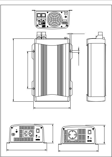
Ø7 mm |
|
|
|
|
|
|
|
313 mm, MSI1300: 342 mm |
367 mm, MSI1800T: 406 mm |
MSI900: 186,5 mm |
MSI1300: 220 mm |
MSI1800: 245 mm MSI1800T: 284 mm |
|
|
|
|
|
|
|
|
|
|
|
10 mm |
|
|
|
|
|
|
|
MSI900: |
MSI1800: |
|
|
|
|
|
|
|
|
|
|
|
|
|
|
|
|
|
|
|
|
|
|
|
|
|
|
|
|
|
|
|
|
|
|
186,6 mm |
|
|
|
|
|
|
|
|
|
|
|
|
|
|
|
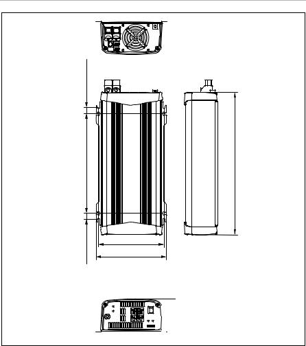
MSI1800T |
|
|
|
|
MSI900, MSI1300, MSI1800 |
||||||||||||||
|
|
|
|
|
|
|
|
|
|
ON |
|
94,5 mm |
|
|
|
|
|
|
|
|
|
|
94,5 mm |
|
|
|
|
|
|
|
|
|
|
OFF |
|
|
|
|
|
|
|
|
|
|
ON |
||
|
|
|
|
|
|
|
|
|
|
REMOTE |
|
|
|
|
|
|
|
|
|
|
OFF |
||
|
|
|
|
|
|
|
|
|
|
|
|
|
|
|
|
|
|
|
|
|
REMOTE |
||
|
|
|
|
|
|
|
|
|
LOAD |
|
|
|
|
|
|
|
|
|
|
|
|||
|
BREAKER |
|
|
|
|
|
|
|
STATUS |
|
|
|
|
|
|
|
|
|
|
|
|||
|
|
|
|
|
|
|
|
|
|
|
|
|
|
|
|
|
|
|
LOAD |
||||
|
|
|
|
AC INPUT |
AC OUTPUT |
VOLT. |
FREQ. |
POWER SAVING |
|
|
|
|
|
|
|
|
|
STATUS |
|||||
|
|
|
|
|
OUT |
1 |
|
|
|
|
OUT |
VOLT. |
FREQ. |
|
POWER |
SAVING |
N.A. OPTION |
||||||
|
|
|
|
|
N.A. OPTION0 |
|
|
|
|
|
|||||||||||||
|
|
|
|
|
1 |
2 |
3 |
4 |
5 6 |
7 8 |
|
|
|
|
|
AC OUTPUT |
|
|
|
|
|
1 |
|
|
|
|
|
|
|
|
|
|
|
|
|
|
|
|
|
|
|
|
|
|
|
0 |
|
|
|
|
|
|
|
|
|
|
|
|
|
|
|
|
|
1 |
2 |
3 |
4 |
5 |
6 |
7 8 |
|
|
|
|
200,6 mm |
|
|
|
|
|
|
|
|
|
|
200,6 mm |
|
|
|
|
|
|
|
||
|
|
|
|
|
|
|
|
|
|
|
|
|
|
|
|
|
|
|
|
|
|
|
|
|
|
|
|
|
|
|
|
|
|
|
|
|
|
|
|
|
|
|
|
|
|
|
9 |
SinePower
f
17,5 mm
283,9 mm
17,5 mm
406 mm
186,6 mm
200,6 mm
MSI1812TOE


 94,5 mm
10
SinePower
Please read this instruction manual carefully before installation and first use, and store it in a safe place. If you pass on the product to another person, hand over this instruction manual along with it.
Table of contents |
|
|
1 |
Explanation of symbols . . . . . . . . . . . . . . . . . . . . . . . . . . . . . . . . . . . . . . . . . |
.12 |
2 |
General safety instructions . . . . . . . . . . . . . . . . . . . . . . . . . . . . . . . . . . . . . . . |
12 |
3 |
Scope of delivery . . . . . . . . . . . . . . . . . . . . . . . . . . . . . . . . . . . . . . . . . . . . . . |
14 |
4 |
Accessories . . . . . . . . . . . . . . . . . . . . . . . . . . . . . . . . . . . . . . . . . . . . . . . . . . . |
14 |
5 |
Target group for this Instruction . . . . . . . . . . . . . . . . . . . . . . . . . . . . . . . . . . . |
15 |
6 |
Intended use . . . . . . . . . . . . . . . . . . . . . . . . . . . . . . . . . . . . . . . . . . . . . . . . . . |
15 |
7 |
Technical description . . . . . . . . . . . . . . . . . . . . . . . . . . . . . . . . . . . . . . . . . . . |
16 |
8 |
Mounting the inverter . . . . . . . . . . . . . . . . . . . . . . . . . . . . . . . . . . . . . . . . . . . |
19 |
9 |
Connecting the inverter . . . . . . . . . . . . . . . . . . . . . . . . . . . . . . . . . . . . . . . . . |
21 |
10 |
Use inverter . . . . . . . . . . . . . . . . . . . . . . . . . . . . . . . . . . . . . . . . . . . . . . . . . . |
26 |
11 |
Cleaning and caring for the inverter. . . . . . . . . . . . . . . . . . . . . . . . . . . . . . . |
30 |
12 |
Troubleshooting . . . . . . . . . . . . . . . . . . . . . . . . . . . . . . . . . . . . . . . . . . . . . . |
30 |
13 |
Warranty . . . . . . . . . . . . . . . . . . . . . . . . . . . . . . . . . . . . . . . . . . . . . . . . . . . . . |
31 |
14 |
Disposal . . . . . . . . . . . . . . . . . . . . . . . . . . . . . . . . . . . . . . . . . . . . . . . . . . . . . . |
31 |
15 |
Technical data . . . . . . . . . . . . . . . . . . . . . . . . . . . . . . . . . . . . . . . . . . . . . . . . |
32 |
11
EN

Explanation of symbols |
SinePower |
1Explanation of symbols
!WARNING!
Safety instruction: Failure to observe this instruction can cause fatal or serious injury.
ANOTICE!
Failure to observe this instruction can cause material damage and impair the function of the product.
INOTE
Supplementary information for operating the product.
2General safety instructions
2.1General safety
The manufacturer accepts no liability for damage in the following cases:
•Faulty assembly or connection
•Damage to the product resulting from mechanical influences and excess voltage
•Alterations to the product without express permission from the manufacturer
•Use for purposes other than those described in the operating manual
!WARNING!
•Only use the device as intended.
•Do not operate the device in a damp or wet environment.
•Do not operate the device near any flammable materials.
•Do not operate the device in areas that are potentially explosive.
•Maintenance and repair work may only be carried out by qualified personnel who are familiar with the risks involved and the relevant regulations.
•People (including children) whose physical, sensory or mental capacities or whose lack of experience or knowledge prevent them from using this product safely should not use it without the supervision or instruction of a responsible person.
12
EN

SinePower |
General safety instructions |
•Electrical devices are not children’s toys
Always keep and use the device out of the reach of children.
2.2Safety when installing the device
!WARNING!
•Installing the device may only be performed by qualified personnel who are familiar with the guidelines and safety precautions to be applied.
•If electrical devices are incorrectly installed on boats, corrosion damage might occur. The device should be installed by a specialist (marine) electrician.
ANOTICE!
•Ensure that the device is standing firmly.
The device must be set up and fastened in such a way that it cannot tip over or fall down.
•Do not expose the device to a heat source (such as direct sunlight or heating). Avoid additional heating of the device in this way.
•If cables have to be fed through metal walls or other walls with sharp edges, use ducts or tubes to prevent damage.
•Do not lay cables which are loose or bent next to electrically conductive material (metal).
•Do not pull on the cables.
•Do not lay the 230 V mains cable and the 12/24 V DC cable in the same duct.
•Fasten the cables securely.
•Lay the cables so that they cannot be tripped over or damaged.
2.3Operating the device safely
!WARNING!
•Only operate the device if you are certain that the housing and the cables are undamaged.
•Even after the fuse triggers, parts of the inverter remain live.
•Always disconnect the power supply when working on the device.
13
EN

Scope of delivery |
SinePower |
ANOTICE!
•Make sure the air inlets and outlets of the device are not covered.
•Ensure good ventilation. The inverter produces dissipated heat which has to be diverted.
•Do not connect the 230 V output of the inverter (fig. 6 5, page 4 to fig. 8 5, page 5) to another 230 V supply.
3Scope of delivery
MSI900, MSI1300, MSI1800
No. in |
|
fig. 1, |
Label |
page 3 |
|
|
|
1 |
Sine wave inverter |
|
|
–Operating instructions
MSI1800T
No. in
fig. 2, Label page 3
1Sine wave inverter
2Connection cable with safety coupling (for 230 Vw output)
3Connection cable with safety plug (for 230 Vw supply)
–Operating instructions
4Accessories
Label |
Item no. |
|
|
Remote control MCR7 |
9600000090 |
|
|
Remote control MCR9 |
9600000091 |
|
|
14
EN

SinePower |
Target group for this Instruction |
5Target group for this Instruction
It is chapter “Connecting the inverter” on page 21 expressly intended for technical people who are familiar with the corresponding VDE-Guidelines.
All other chapters are also intended for the users of the device.
6Intended use
!WARNING!
Never use the inverter on vehicles where the positive terminal of the battery is connected to the chassis.
The wave inverter converts direct current of
•12 Vg:
SinePower MSI912 SinePower MSI1312 SinePower MSI1812 SinePower MSI1812T SinePower MSI1812TOE
•24 Vg:
SinePower MSI924 SinePower MSI1324 SinePower MSI1824 SinePower MSI1824T
into a 200 – 240 V AC supply of 50 Hz or 60 Hz.
15
EN

Technical description |
SinePower |
7Technical description
The inverters can be operated wherever
•a 12 Vg connection (MSI912, MSI1312, MSI1812, MSI1812T, MSI1812TOE)
•a 24 Vg connection (MSI924, MSI1324, MSI1824, MSI1824T)
is available. The light-weight and compact construction of this device allows for easy installation in mobile homes, commercial vehicles or motor and sailing yachts.
The output voltage corresponds to the household voltage from the socket (pure sine wave, THD < 3 %).
Please observe the values for constant output power and peak output power as indicated in chapter “Technical data” on page 32. Never connect devices that have a higher power requirement.
INOTE
Note when connecting devices with an electrical drive (such as power drills and refrigerators), that they often require more power than is indicated on the type plate.
The inverter has various protective mechanisms.
•Overvoltage protection: The inverter shuts itself off when the voltage exceeds the cut-off value. It restarts when the voltage returns to the restart value.
•Low-voltage protection: The inverter shuts itself off when the voltage sinks below the cut-off value. It restarts when the voltage rises to the restart value.
•High temperature protection: The inverter switches off when the temperature inside the device or the temperature on the cooling element exceeds a cut-off value. It restarts when the temperature has reduced.
•Overload protection: The LED on the inverter indicates an operating fault (constant red light) when an excess load is connected or a short circuit has occurred. The fuse in the device must be pressed in again by hand after it is triggered by excess current.
•Incorrect polarity protection: The incorrect polarity protection prevents the wrong polarity when connecting the inverter.
•Device fuse (only MSI1812T, MSI1812TOE, MSI1824T): The LED on the inverter indicates an operating fault (constant red light). The fuse in the device must be pressed in again by hand after it is triggered.
INOTE
The individual switching values are found in chapter “Technical data” on page 32.
16
EN

SinePower |
Technical description |
In addition the device can be configured over an RS-232 interface by a PC and with the DIP switches on the device.
The inverter can be switched to an energy-saving mode to prevent the connected battery from discharging too quickly.
The inverter can be easily controlled with a remote control (accessory).
The inverters SinePower MSI1812T, MSI1812TOE, MSI1824T are fitted with a 230 Vw priority circuit. If there is an external 230 Vw voltage this is used as a first
priority. If no external 230 Vw voltage is connected, then the connected battery will be used as the power supply.
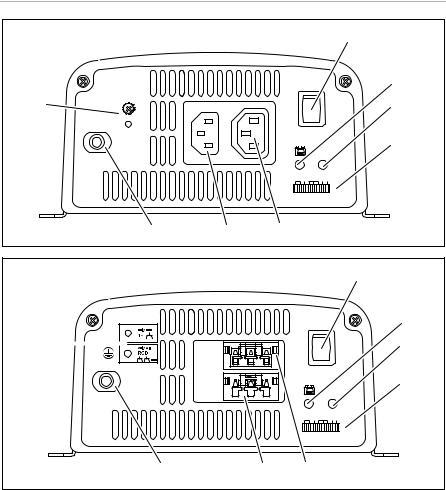
7.1Controls
INOTE
The version for continental Europe is depicted.
The inverter has the following connections, displays and control elements on the back:
No. in |
|
|
fig. 5, |
Label |
Description |
page 4 |
|
|
|
|
|
1 |
Terminal |
Set up operation via remote control |
|
|
|
2 |
RS-232 port, |
Connection of a PC using a serial RS-232 interface or |
|
REMOTE port |
connection of the MCR7 or MCR9 remote control |
|
|
|
3 |
POS+ |
Positive terminal |
|
|
|
4 |
NEG– |
Negative terminal |
|
|
|
5 |
Earth terminal |
Earthing on the vehicle bodywork |
|
|
|
17
EN

Technical description |
SinePower |
MSI900, MSI1300, MSI1800
The inverter has the following connections, displays and control elements on the front:
No. in |
|
|
fig. 6, |
Label |
Description |
page 4 |
|
|
|
|
|
1 |
Main switch |
Switches the device on, off or to operation via the |
|
“ON/OFF/REMOTE” |
remote control (accessory) |
|
|
|
2 |
“Input Level” LED |
Displays the input voltage range |
|
|
|
3 |
“Load Level” LED |
Displays the power being supplied |
|
|
|
4 |
Dip switch |
Makes settings on the inverter (such as mains voltage, |
|
|
mains frequency, energy-saving mode). |
|
|
|
5 |
Safety socket |
230 V output |
|
|
|
MSI1800T
The inverter has the following connections, displays and control elements on the front:
No. in |
|
|
fig. 7, |
Label |
Description |
page 5 |
|
|
|
|
|
1 |
Main switch |
Switches the device on, off or to operation via the |
|
“ON/OFF/REMOTE” |
remote control (accessory) |
|
|
|
2 |
“Input Level” LED |
Displays the input voltage range |
|
|
|
3 |
“Load Level” LED |
Displays the power being supplied |
|
|
|
4 |
Dip switch |
Makes settings on the inverter (such as mains voltage, |
|
|
mains frequency, energy-saving mode). |
|
|
|
5 |
AC output |
230 V output |
|
|
|
6 |
AC input |
230 V input |
|
|
|
7 |
Fuse |
Protects the inverter from overload. |
|
|
The fuse can be pressed in again once it has trig- |
|
|
gered. |
|
|
|
8 |
Earthing screw |
Sets or removes the grounding bridge |
|
|
|
18
EN

SinePower |
Mounting the inverter |
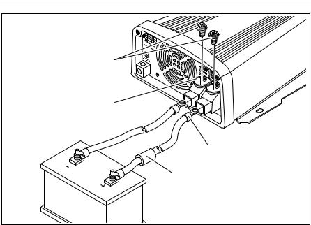
MSI1800TOE
The inverter has the following connections, displays and control elements on the front:
No. in |
|
|
fig. 8, |
Label |
Description |
page 5 |
|
|
|
|
|
1 |
Main switch |
Switches the device on, off or to operation via the |
|
“ON/OFF/REMOTE” |
remote control (accessory) |
|
|
|
2 |
“Input Level” LED |
Displays the input voltage range |
|
|
|
3 |
“Load Level” LED |
Displays the power being supplied |
|
|
|
4 |
Dip switch |
Makes settings on the inverter (such as mains voltage, |
|
|
mains frequency, energy-saving mode). |
|
|
|
5 |
AC input |
230 V input |
|
|
|
6 |
AC output |
230 V output |
|
|
|
7 |
Fuse |
Protects the inverter from overload. |
|
|
The fuse can be pressed in again once it has trig- |
|
|
gered. |
|
|
|
8 |
Earthing screw |
Sets or removes the grounding bridge |
|
|
|
8Mounting the inverter
8.1Tools required
For the electrical connection you will need the following tools:
•Crimping tool
•3 multi-coloured, flexible connection cables. You can see the required cross section for cable lugs and conductor sleeves in the table in the chapter “Connecting the inverter” on page 21.
•Cable lugs and conductor sleeves.
For fastening the inverter you will require the following tools:
•Machine bolts (M4) with washers and self-locking nuts or
•self-tapping screws or wood screws.
19
EN

Mounting the inverter |
SinePower |
8.2Installation instructions
When selecting the installation location, note the following:
•The inverter can be mounted horizontally or vertically.
•The inverter must be installed in a place that is protected from moisture.
•The inverter may not be installed in the presence of flammable materials.
•The inverter may not be installed in a dusty environment.
•The place of installation must be well ventilated. A ventilation system must be
available for installations in small, enclosed spaces. The minimum clearance around the inverter must be at least 25 cm (fig. 3, page 3).
•The air intake on the underside or the air outlet on the back of the inverter must remain clear.
•For ambient temperatures higher than 40 °C (such as in engine or heating compartments, or direct sunlight), the heat from the inverter under load can lead to automatic shutdown.
•The device must be installed on a level and sufficiently sturdy surface.
ANOTICE!
Before drilling any holes, make sure that no electrical cables or other parts of the vehicle can be damaged by drilling, sawing and filing.
8.3Mounting the inverter
Hold the inverter against the installation location you have chosen and mark the fastening points (fig. 4 A, page 4).
Attach the inverter using your chosen fastening method (fig. 4 B, page 4).
20
EN
SinePower |
Connecting the inverter |
9Connecting the inverter
9.1General instructions
!WARNING!
•The inverter may only be connected by a suitably qualified technician. The following information is intended for technicians who are familiar with the guidelines and safety precautions to be applied.
•For vehicles in which the positive terminal of the battery is connected with the chassis the inverter must not be installed.
•If you do not fit a fuse to the positive cable, the cables can overload, which might result in a fire.
•Reversed polarity can damage the inverter.
•MSI900, MSI1300, MSI1800: The inverter must not be used in a ring main, but only used for supplying individual devices with electricity. These devices must be plugged directly into the inverter, or connected to the inverter using a sheathed extension cable manufactured for this purpose.
•When installed in vehicles or boats, the inverter must be connected to the chassis or earth.
•When setting up a socket distribution circuit (mains set up), comply with VDE 0100.
•Only use copper cables.
•Keep the cables as short as possible (< 1.8 m).
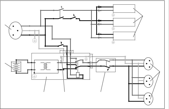
•Keep to the required cable cross section and fit a cable fuse (fig. 9 3, page 6) as close as possible to the battery in the positive cable (see Table).
Device |
Required cable |
Cable fuse |
|
cross section |
(fig. 9 3, page 6) |
||
|
|||
|
|
|
|
MSI912 |
25 mm² |
115 A |
|
|
|
|
|
MSI924 |
25 mm² |
75 A |
|
|
|
|
|
MSI1312 |
35 mm² |
170 A |
|
|
|
|
|
MSI1324 |
35 mm² |
85 A |
|
|
|
|
|
MSI1812/MSI1812T/ |
35 mm² |
228 A |
|
MSI1812TOE |
|
|
|
|
|
|
|
MSI1824/MSI1824T |
35 mm² |
115 A |
|
|
|
|
21
EN

Connecting the inverter |
SinePower |
9.2Connecting the inverter to the battery
INOTE
Tighten the screws or nuts with a torque of 12 – 13 Nm. Loose connections may cause overheating.
Put the main switch (fig. 6 1, page 4 to fig. 8 1, page 5) on ‘OFF’.
Loosen the screw (fig. 9 1, page 6) from the red positive terminal (fig. 9 2, page 6).
Push the cable lug (fig. 9 2, page 6) of the positive cable into the red positive terminal and fasten it with the screw.
Connect the negative cable corresponding to the black negative terminal (fig. 9 4, page 6).
Lay the positive cable from the inverter to the positive terminal of the vehicle battery and connect it.
Lay the negative cable from the inverter to the negative terminal of the vehicle battery and connect it.
Connect the earth terminal with the vehicle body earth.
9.3 Connect the 230 V supply cable (only MSI1800T, MSI1800TOE)
Plug in the 230 Vw connection cable with Schuko plug into the 230 Vw input bush (fig. 7 6, page 5 and fig. 8 5, page 5).
Connect the Schuko plug to the 230 V AC mains.
9.4 Connect the 230 V output cable (only MSI1800T, MSI1800TOE)
!WARNING!
Before connecting the 230 V output cable, make sure the inverter is switched off at the main switch.
Plug the 230 Vw connection cable with Schuko coupling into the 230 Vw output bush (fig. 7 5, page 5 and fig. 8 5, page 5).
22
EN

SinePower |
Connecting the inverter |
9.5Connect several loads
(only MSI1800T, MSI1800TOE)
The device is equipped with galvanic isolation when delivered. For the safe operation of multiple loads, it is essential that a circuit breaker (residual current circuit breaker) is built into the socket distribution circuit, see sample circuit diagram in fig. 0, page 7.
Sample circuit diagram legend:
No. in
fig. 0, Explanation page 7
1230 Vw power source
2 |
Additional devices, e.g. battery charger, refrigerator |
3DC power source (battery)
4Inverter
5Grounding bridge set (At delivery: not set, shown by dotted line)
6Circuit breaker (residual current circuit breaker)
7Socket distribution circuit for load unit
!WARNING! Danger of electrocution
If you wish to connect more than one load unit to the inverter and install a socket distribution circuit, you must arrange a circuit breaker (residual current circuit breaker) and put an earthing strap in the inverter.
Install a residual current circuit breaker in the socket distribution circuit.
9.6Connect earthing strap (only MSI1800T, MSI1800TOE)
MSI1800T: fig. 7 8. page 5
MSI1800TOE: fig. 8 8. page 5
Screw the earthing screw out of the upper hole.
Screw the screw in the lower hole in.
23
EN

Connecting the inverter |
SinePower |
9.7Connecting the MCR7 or MCR9 remote control (accessory)
ANOTICE!
•Only plug in the connection to the remote control in the remote port. The device can be damaged by connecting it incorrectly.
•Ensure that the remote control and inverter are supplied with the same input voltage.
•Follow the instruction manual of the remote control.
Connect the remote control (accessory) on the remote port (fig. 5 2, page 4).
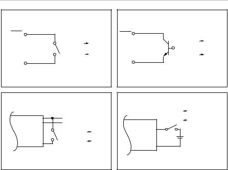
9.8Connect external switch to turn device on and off
INOTE
Use cable with a cable cross section of 0.25 – 0.75 mm².
You can use the following as an external switch:
•external switch, voltage supply from the inverter: fig. a, page 8
•Control unit with relay or transistor circuit (TR): fig. b, page 8
•external switch with voltage supply from the battery (BAT) of the vehicle: fig. c, page 8
•external switch with its own voltage supply (DC POWER) e.g. from the ignition: fig. d, page 8
Put the main switch (fig. 6 1, page 4 to fig. 8 1, page 5) to ‘OFF’ and ensure that the connection for the remote control (fig. 5 2, page 4) is not filled.
Put the main switch (fig. 6 1, page 4 to fig. 8 1, page 5) to ‘REMOTE’.
Connect the external on/off switch with the connection cable to the terminal (fig. 5 1, page 4).
24
EN

SinePower |
Connecting the inverter |
9.9Pin assignment
INOTE
Keep the cable lengths as short as possible (< 10 m) so that there are no losses in the signal transmission.
The pins of the RS-232 ports are assigned as follows:
|
Inverter |
Computer |
|
|
|
|
|
Pin |
Description |
Description |
Pin |
|
|
|
|
1 |
Not assigned |
Not assigned |
1 |
|
|
|
|
2 |
GND |
RXD |
2 |
|
|
|
|
3 |
RXD |
TXD |
3 |
|
|
|
|
4 |
TXD |
DTR |
4 |
|
|
|
|
5 |
Not assigned |
GND |
5 |
|
|
|
|
6 |
Not assigned |
DSR |
6 |
|
|
|
|
|
|
RTS |
7 |
|
|
|
|
|
|
CTS |
8 |
|
|
|
|
|
|
Not assigned |
9 |
|
|
|
|
The pins of the RJ11 remote control connection are assigned as follows:
|
Inverter |
Pin |
Description |
|
|
1 |
– |
|
|
2 |
GND |
|
|
3 |
RS-232 RXD |
|
|
4 |
RS-232 TXD |
|
|
5 |
RMT remote control |
|
|
6 |
Not assigned |
|
|
25
EN

Use inverter |
SinePower |
10 Use inverter
10.1Switching on inverter
Put the main switch (fig. 6 1, page 4 to fig. 8 1, page 5) of the inveter in switch position’ON’.
Set the On/Off switch to “OFF” to switch off.
The inverter performs a self-test.
During the self-test, the built-in speaker emits tones and the LEDs flash.
After the successful self test the LEDs ‘Input level’ light.(fig. 6 2, page 4 to fig. 8 2, page 5) and ‘Load Status’ (fig. 6 3, page 4 to fig. 8 3, page 5) green.
Note the following instructions in operation (see also chapter “Troubleshooting” on page 30
The inverter switches off if:
•the battery voltage drops below 10.5 V (12 Vg connection) or 21 V (24 Vg connection),
•the battery voltage rises over 16 V (12 Vg connection) or 32 V (24 Vg connection),
•the inverter overheats.
Switch the inverter off with the main switch in this case (fig. 6 1, page 4 to fig. 8 1, page 5).
Check that the inverter is sufficiently ventilated and that the ventilation grilles are unimpeded.
Wait about 5 – 10 minutes and switch the inverter on again without loads.
When operating the inverter at high load for lengthy periods, it is advisable to start the engine in order to recharge the vehicle battery.
26
EN

SinePower |
Use inverter |
10.2Status indications
LED ‘Input Level’ (fig. 6 2, page 4 to fig. 8 2, page 5)
The “Input Level” LED shows the present range of the input voltage.
Display |
Input voltage |
|
|
MSI912, MSI1312, |
|
|
MSI924, MSI1324, |
|
|
MSI1812, MSI1812T, |
|
|
MSI1824, MSI1824T |
|
|
MSI1812TOE |
|
|
|
|
|
|
|
Red, slow flash |
+ 10.6 V |
+ 21.2 V |
|
|
|
Red |
10.6 – 11.0 V |
21.2 – 22.0 V |
|
|
|
Orange |
11.0 – 12.0 V |
22.0 – 24.0 V |
|
|
|
Green |
12.0 – 14.2 V |
24.0 – 28.4 V |
|
|
|
Orange, flashing |
14.2 – 15.0 V |
28.4 – 30.0 V |
|
|
|
Red, quick flashing |
> 15.0 V |
> 30.0 V |
|
|
|
LED ‘Input Level’ (fig. 6 3, page 4 to fig. 8 3, page 5)
The “Load Level” LED shows the power being supplied by the inverter.
Display |
|
Input voltage |
|
|
|
|
MSI1812, |
|
MSI 912, |
MSI1312, |
MSI1812T, |
|
MSI1812TOE, |
||
|
MSI924 |
MSI1324 |
|
|
MSI1824, |
||
|
|
|
|
|
|
|
MSI1824T |
|
|
|
|
Off |
0 – 80 W |
0 – 120 W |
0 – 160 W |
|
|
|
|
Green |
80 – 320 W |
120 – 480 W |
160 – 640 W |
|
|
|
|
Orange |
320 – 720 W |
480 – 1080 W |
640 – 1440 W |
|
|
|
|
Red, slow flash |
720 – 800 W |
1080 – 1200 W |
1440 – 1600 W |
|
|
|
|
Red, quick flash |
> 800 W |
> 1200 W |
> 1600 W |
|
|
|
|
27
EN

Use inverter |
SinePower |
10.3Configuring the inverter
INOTE
Settings can only be made using the dip switch if the S8 dip switch S8 is in the position ‘On’.
You can adjust the device with the help of he dip-switch (fig. 6 4, page 4 to fig. 8 4, page 5).
Setting the mains voltage
You can set the mains voltage using the S1 and S2 dip switches.
|
|
Dip switch |
|
|
|
|
|
Mains voltage |
S1 |
|
S2 |
|
|
|
|
200 V |
Off |
|
Off |
|
|
|
|
220 V |
On |
|
Off |
|
|
|
|
230 V |
Off |
|
On |
|
|
|
|
240 V |
On |
|
On |
|
|
|
|
Setting the mains frequency
!WARNING! Danger of electrocution
Only adjust the S3 DIP switch when the respective frequency for the output voltage should be used.
You can set the mains frequency using the S3 dip switch.
|
Dip switch |
Net frequency |
S3 |
|
|
50 Hz |
Off |
|
|
60 Hz |
On |
|
|
28
EN

SinePower |
Use inverter |
Switching to energy-saving mode
You can set the energy-saving mode using the S4, S5 and S6 dip switches. In this way, the battery you connect to the inverter is not discharged as quickly.
The inverter operates in energy-saving mode as long as the required power is below the set level. If the required power exceeds the set level, the inverter works in normal mode.
The values to be set on your inverter can be found in the following table:
|
Energy-saving mode |
|
|
|
Dip switch |
|
MSI900 |
MSI1300 |
MSI1800 |
S4 |
S5 |
S6 |
|
|
|
|
|
|
|
|
Off |
Off |
|
Off |
Off |
Off |
Off |
|
|
|
|
|
|
|
– |
60 – 120 W |
110 |
– 190 W |
On |
Off |
Off |
|
|
|
|
|
|
|
70 – 110 W |
130 – 170 W |
190 |
– 240 W |
On |
On |
Off |
|
|
|
|
|
|
|
180 – 240 W |
180 – 240 W |
240 – 300 W |
On |
On |
On |
|
|
|
|
|
|
|
|
Define settings
You can specify whether the works settings or the settings of the switch S1 – S7 should be used with the dip switch S8
|
|
Dip switch |
Parameter |
|
S8 |
|
|
|
Works settings |
|
On |
|
|
|
Use dip switch S1 – S7 |
|
Off |
|
|
|
Works settings |
|
|
|
|
|
Mains voltage |
Net frequency |
Energy-saving mode |
|
|
|
230 V |
50 Hz |
Off |
|
|
|
29
EN

Cleaning and caring for the inverter |
SinePower |
11 Cleaning and caring for the inverter
ANOTICE!
Do not use sharp or hard objects or cleaning agents for cleaning as these may damage the product.
Occasionally clean the product with a damp cloth.
12 Troubleshooting
!WARNING!
Do not open the device. You risk sustaining an electric shock by doing this.
INOTE
If you have detailed questions on the specifications of the inverter please contact the manufacturer (addresses on the back of the instruction manual).
The ‘Load Status’ LED (fig. 6 3, page 4 to fig. 8 3, page 5) red indicates a fault:
LED display |
Cause |
Remedy |
|
|
|
Quick flashing |
Input voltage is too high |
Check the input voltage and reduce it. |
|
|
|
Slow flashing |
Input voltage too low |
The battery needs recharging. |
|
|
Check the cables and connections. |
|
|
|
Occasional flashOverheating ing
Switch off the inverter and the load.
Wait about 5 – 10 minutes.
The inverter is being reset.
Then switch the inverter back on without the load.
Reduce the load and make sure the inverter has better ventilation. Then switch the load back on.
30
EN
 Loading...