


Dometic RM24A, RM36C, RM46, RM47, RM66 Service Manual
...
2
|
|
|
|
|
|
|
|
Service Instructions for Domtic Absorption Refrigerators |
|
|
|
||||||||||||||||||||||||||
|
|
The |
absorption refrigerators |
|
described in |
|
this |
manual |
are primarily for |
installation |
|
||||||||||||||||||||||||||
|
|
in |
recreational |
vehicles. |
|
|
|
|
|
|
|
|
|
|
|
|
|
|
|
|
|
|
|
|
|
|
|
|
|
||||||||
|
|
Since the vehicles ni which |
the refrigerato s are located may |
be |
driven |
|
to remote |
|
|||||||||||||||||||||||||||||
|
|
c a m p sites |
wh ere electrical power is |
not |
available, the |
refrigerator5 have |
b e e n |
|
|
|
|||||||||||||||||||||||||||
|
|
odesignedf b ocot operatel |
byp rmeano p sa n e o r |
b u t a n e |
g a s |
|
a s |
we ll a s |
b |
y |
|
|
|
||||||||||||||||||||||||
|
|
e l e c t r i c i ty |
12/110V. |
|
|
|
|
|
|
|
|
|
|
|
|
|
|
|
|
|
|
|
|
|
|
|
|
|
|
||||||||
|
|
These Service Instructions |
|
cover |
the Dometic Models RM24, RM36C, |
|
|
|
|
|
|
|
|
||||||||||||||||||||||||
|
|
RM46, RM47, |
RM66, |
RM67, |
RM76, RM77. |
|
|
|
|
|
|
|
|
|
|
|
|
|
|
|
|
|
|
|
|
||||||||||||
|
|
|
|
|
|
|
|
|
|
|
|
|
|
|
LIST OF CONTENTS |
|
|
|
|
|
|
|
|
|
|
|
|
|
|
||||||||
|
|
|
|
|
|
|
|
|
|
|
|
|
|
|
|
|
|
|
|
|
|
|
|
|
|
|
|
|
|
|
|
|
|
||||
|
Description |
|
|
|
|
|
|
|
|
|
|
Pag |
|
|
|
|
|
|
Description |
|
|
|
|
|
|
|
|
|
Page |
||||||||
|
|
|
|
|
|
|
|
|
|
|
|
|
|
|
|
|
|
|
|
|
|
|
|
|
|
|
|||||||||||
ECHNIGU FE AT UR ES |
|
|
|
|
|
|
|
|
|
|
|
|
|
|
|
|
ELECTRIC OPERATION |
- FUNCTIONAL PARTS |
|
|
|||||||||||||||||
|
Ca bine tes, |
. ..equipment |
._ |
. . . . |
.. . ......... |
|
|
|
. . |
.. |
. |
|
3 |
|
|
|
|
|
|
Re place |
mentof heater_______________.__. |
37 |
|||||||||||||||
INSTALLATION INSTRUCTIONS |
|
|
|
|
|
|
|
|
|
|
|
|
|
|
|
|
Wiring dia gr ams ................................ |
|
|
|
|
|
|
|
38 |
||||||||||||
|
General instructions . |
____ . |
. . . |
. . |
|
. |
. . |
. |
. |
|
4 |
|
|
|
|
.PRESSURE MEASURING DEVICES |
. . . . . . |
. . . |
. . . . . |
39 |
|||||||||||||||||
|
Ventilation__ |
. . . . |
|
. . . |
. |
. |
. . . |
. . . |
. . |
. |
. |
. . |
. |
. |
|
5 |
|
|
|
|
OPERATING |
RE COMMENDA TIONS |
|
|
|
|
|
|
|||||||||
|
Gas connections ____ ___ |
|
|
|
|
|
|
|
|
5 |
|
|
|
|
|
|
|
|
|
|
|||||||||||||||||
|
. . . |
. . . |
|
. . |
. |
. |
. . |
|
|
|
|
|
|
|
Gas operation _______ _____ _______ _____ |
40 |
|||||||||||||||||||||
|
Electrical |
connections___________.. |
______ |
|
5 |
|
|
|
|
|
|
Electric |
|
operation . |
. . . |
|
. |
. |
. . . . . |
. . . |
. . . |
41 |
|||||||||||||||
|
Approved |
installations |
|
|
|
|
|
|
|
|
7 |
|
|
|
|
MAINTENANCE |
|
|
|
|
|
|
|
|
|
|
|
|
|||||||||
|
Me asure ments ... . . . . . . . . . . . . . . . . . . . . |
|
10 |
|
|
|
|
|
|
L evelling_________ . . |
. . . |
|
. |
. |
. . . . . . |
. . |
. . . |
42 |
|||||||||||||||||||
Ca binet A d j u s t m e n t s |
|
|
|
|
|
|
|
|
|
|
|
|
|
|
|
|
|
T e m p e r a t u r e |
C o n t r o l |
( t h e r m o s t a t ) . . . . |
4 2 |
||||||||||||||||
|
|
|
|
|
|
|
|
|
13 |
|
|
|
|
|
|
|
|
|
|
|
|
42 |
|||||||||||||||
|
To change the door panel _ . _ ____ _____ . |
. |
. . |
|
|
|
|
|
|
|
The themostat |
capillary |
|
tube . . . . |
. . |
. . . . |
|||||||||||||||||||||
|
Replacement of door gasket ___ . ________ .. |
|
15 |
|
|
|
|
|
|
Storing food in the refrigerator_______. |
43 |
||||||||||||||||||||||||||
|
Replacement of evaporator door and gasket. |
|
16 |
|
|
|
|
|
|
Cleaning |
____ |
. . . . . ______ |
. . . . . . . . |
. . |
. . . . . |
43 |
|||||||||||||||||||||
|
Reversing outer |
door__ |
. . |
.. . . |
. . . . |
. . . |
. |
. . |
. |
___ |
|
18 |
|
|
|
|
|
|
Ice cubes___________ ____ ______________ |
43 |
|||||||||||||||||
THE AB SORPTION REFRIGRATOR SYSTE M |
|
|
|
|
|
|
|
|
|
|
|
|
|
Travel latch ____ ____ ____ |
. . . . . . . . |
. . |
. . . . . |
43 |
|||||||||||||||||||
|
Sealed system |
constructions . . _ _ _ _ . |
. |
. . |
. |
. . |
|
20 |
|
|
|
|
|
|
Door seal_ . . |
. . . |
. ___ ______ ______ ____ ___ |
43 |
|||||||||||||||||||
|
Operating analysis for cooling unit |
. |
. . |
. . |
. |
|
22 |
|
|
|
|
|
|
Odors inside the |
refrigerator . . . . |
. . . |
. . . . . |
44 |
|||||||||||||||||||
|
Cooling unit replacement . . . |
. . . |
. . . |
. . |
. |
. . |
. |
. . |
|
23 |
|
|
|
|
|
|
Odors from |
fumes |
|
|
|
|
.......... |
|
....... |
44 |
|||||||||||
GAS /ELECTRIC EQUIPMENT |
|
|
|
|
|
|
|
|
|
|
|
|
|
|
|
|
|
|
Flame blows |
out . . |
. . . |
........ |
|
|
|
. ____ |
________ |
44 |
|||||||||
|
Gas equipment |
for RM24 ..... |
. . . . |
. . |
. . |
. |
. .. |
. |
. |
|
28 |
|
|
|
|
|
|
Flint lighter_______ |
. . . |
. |
|
. . |
. . . . . . |
. . |
. . . . |
44 |
|||||||||||
|
Dual electri c |
equipment for |
RM24 . . . |
. |
. . |
. |
. |
|
29 |
|
|
|
|
|
|
Piezo lighter ____________ _ ____ _________ |
45 |
||||||||||||||||||||
|
C a r / e l e c t r i c |
equ ipment for |
RM36C, |
|
|
|
|
|
30 |
|
|
|
|
|
DIAGNOSIS |
|
|
|
|
|
|
|
|
|
|
|
|
|
|||||||||
|
RM46, RM47, RM66, RM67 , RM76, RM77... |
|
_ _ _ _ |
|
|
|
|
|
|
|
Trouble shooting |
- |
electric operated |
|
|||||||||||||||||||||||
|
AS OPERATION - |
FU NCTIO NAL PARTS |
|
|
|
|
|
|
|
|
|
|
|
|
47 |
||||||||||||||||||||||
|
|
|
|
|
|
|
|
|
|
|
|
|
refrigerators |
_____ |
__ |
. . . |
|
. |
. . |
. . . . . . |
. . . |
. . . . |
|||||||||||||||
|
Termostat- |
replacment___ . . . . . |
. . . . |
. . . |
. . |
|
|
|
|
|
32 |
|
|
|
|
|
|
T r o u b l e |
shooting - |
gas operated |
|
|
48 |
||||||||||||||
|
The gas burner |
|
|
|
|
|
|
|
|
|
|
|
|
|
|
33 |
|
|
|
|
|
|
refrigerators_______ |
. . . . |
. |
|
. . |
. . . . . . . |
. ...... |
|
|||||||
|
...... |
|
. . . |
.. |
. . |
. . .. |
. . . . |
. . . |
. . |
. |
. . . |
. |
|
|
|
|
|
|
|
|
Failed refrigerating unit_____ |
_____._ |
49 |
||||||||||||||
|
Flue system |
|
|
|
|
|
|
|
|
|
|
|
|
|
|
|
34 |
|
|
|
|
|
|
||||||||||||||
|
. . |
. . . |
. |
. . . |
. |
. . |
. . ......... |
|
. . |
. . |
. |
. . |
. |
. |
|
|
|
|
|
|
|
Operation |
analysis |
for |
electric |
|
|
|
|||||||||
|
Thermo flame failure device |
|
|
|
|
|
|
|
|
35 |
|
|
|
|
|
|
|
|
50 |
||||||||||||||||||
|
. . . |
. . . . |
. . |
. |
. . |
. |
. . |
|
|
|
|
|
|
|
operated refrigerators . |
. |
. . |
. . . . . . . . . |
. . |
. . . . . |
|||||||||||||||||
|
|
|
|
|
|
|
|
|
|
|
|
|
|
|
|
|
|
|
|
|
|
|
|
Operation analysis for LP gas |
|
|
|
||||||||||
|
|
|
|
|
|
|
|
|
|
|
|
|
|
|
|
|
|
|
|
|
|
|
|
operated refrigerators . |
. |
. . |
. . . . . . . |
. . |
. . . . . |
51 |
|||||||
|
|
|
|
|
|
|
|
|
|
|
|
|
|
|
|
|
|
|
|
|
|
|
|
Periodic |
|
m a i n t e nea n c |
. . |
. |
|
. . |
. . . . . . |
.. . . . . |
52 |
||||
|
|
|
|
|
|
|
|
|
|
|
|
|
|
|
|
|
|
|
|
|
|
|
|
|
|
|
|
|
|
|
|
|
|
|
|
|
|


4
Door |
|
|
All models will be delivered |
with right hand door hinging, |
but it is possible for |
the customer to change the |
door hinging from right to left |
hand. |
Replacement of door panel is possible without removing the door. Only the side profile of the door frame has to be removed.
Equipment
All models incorporate a thermo-electric flame failure safety device and a piezo
lighting |
system. |
|
|
|
The |
equipment for electric and gas operation |
is located at the rear of the cabinet |
||
and manipulated from inside the cabinet. |
|
|||
The |
gas shut-off valve and the electric voltage-change switch are interlocked so |
|||
that |
both methods of operation cannot be inadvertently used at the same time. |
|||
The electric and gas thermostats are of the Ranco-make. |
||||
Version |
|
|
|
|
All |
models will be available with combination |
equipments for LP gas and 110 volts |
||
A.C. |
or LP gas/110 volts A.C. and 12 volts D.C. |
|||
2. |
INSTALLATION |
INSTRUCTIONS |
|
|
For LP-gas and electric operation in Motor Homes and Recreational Vehicles. |
||||
General |
instructions |
|
||
The |
refrigerators |
outlined herein have been |
design certified under ANS 221.19 |
|
Refrigerators by the American Gas Association for installation in a mobile home or recreational vehicle and are approved by the Canadian Gas Association.
The certifications are, however, contingent on the installation being made in accordance with the following instructions,
The installation must conform with:
In U.S.A.:
1. Installation of Gas Appliance and Gas Piping, 221.30 - 1964.
2 . |
Mobile Homes A 119.1 |
- |
1969. |
3. |
Recreational Vehicles |
A |
119.2 - 1970. The unit must be electrically grounded in |
accordance with the National Electrical Code ANSI |
CI |
- 1968, when installed if |
an external alternating current electrical source |
is |
utilized. |
4. Any applicable local code, |
|
|
In Canada: |
|
|
1. C S A Standard B 149. “Installation Code for Gas Burning Appliances and Equipment”
2 . C S A Standard B 210.1/Z 240.4. “Gas equipped recreational vehicles and mobile homes”

5
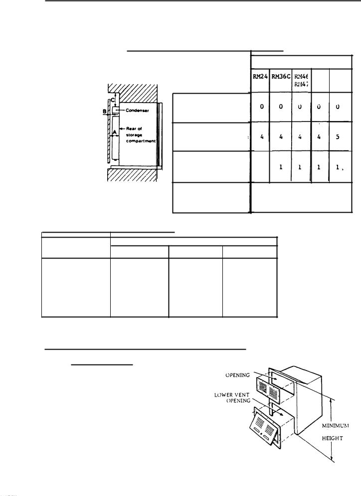
V e n t i l a t i o n
The installation shall be made in such a manner as to separate the combustion system from the living space of the recreational vehicle. Openings for air supply or for venting of combustion products shall have a minimum dimension of not less than
l/4 inch.
Approved installation requires one lower fresh air intake and one upper exhaust vent. The accessory ventilation kits shown in these instructions have been tested
and approved for use with the refrigerator models identified. Their use is recommen ded, and when employed, the ventilation kits must be installed and used without modification,
An opening to the outside at floor level of the refrigerator compartment must be provided for ventilation of heavier-than-air fuel gases, The lower vent in the Dometic kits is provided with proper size openings.
Gas connect ion
Hook-up to the gas supply line is accomplished at the manual gas valve, which is
furnished with a |
3/8” (SAE) male flare |
connection. All |
completed connections should |
|
be checked for leaks with soapy water. |
|
|
|
|
CAUTION: When connecting the gas line |
to the gas valve |
on the gas/e1 equipment |
at |
|
the rear of the refrigerator, use a back-up wrench to prevent undue |
|
|||
rotation |
of the gas c o c k , |
|
|
|
For hook-up and |
servicing purpose the |
lower vent is constructed as a lift out |
panel. |
|
The gas supply system must incorporate a pressure regulator to maintain a supply pressure of not more nor less than 11 inches water gage.
Electrical connections 110 V A.C.
The 110 V electric cord should be plugged into an approved receptacle in the
refrigerator compartment. The cord should |
be routed to avoid coming in contact witn |
|
the |
burner cover, flue cover or other hot |
components. |
12 |
V D.C. |
|
On “Tri-Power” units there is an additional terminal block marked “12 V”. The refri-
gerator must be |
connected to the battery circuit |
with two wires of adequate capacity |
|||
to avoid voltage |
drop. |
|
|
|
|
Do not use the body or chassis |
as a substitute for either of these wires (possibly |
||||
only in motor homes). No other |
electrical equipment or lighting should be connected |
||||
to the refrigerator circuit. |
|
|
|
|
|
When estimating length and area of conductor cable, see table, page 6. |
|||||
CAUTION : |
|
|
|
|
|
Do not operate the refrigerator |
on |
12 Volt when |
the vehicle is |
parked. You will run |
|
the battery dead |
in a rather short |
time. |
|
|
|
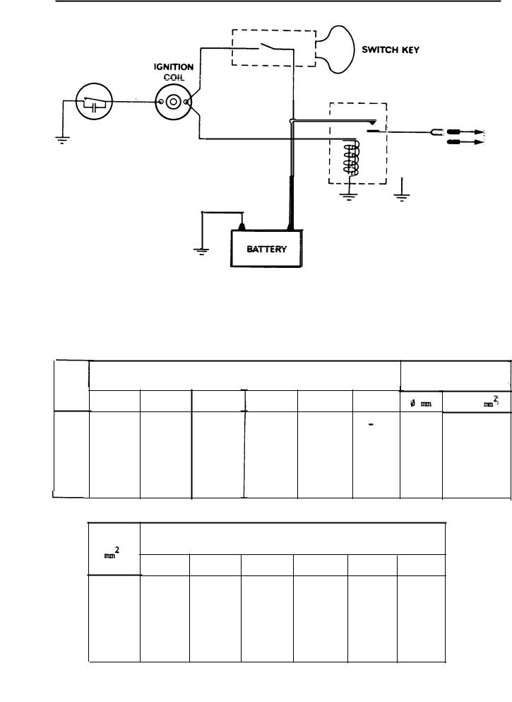
If possible the installation of a |
12 |
Volt operated |
refrigerator |
should be c o m p l e t e d |
|
with a relay mounted either in |
the car or in the vehicle (see diagram). This relay |
||||
will automatically cut out the refrigerator when |
the car motor is stopped. |
||||


14
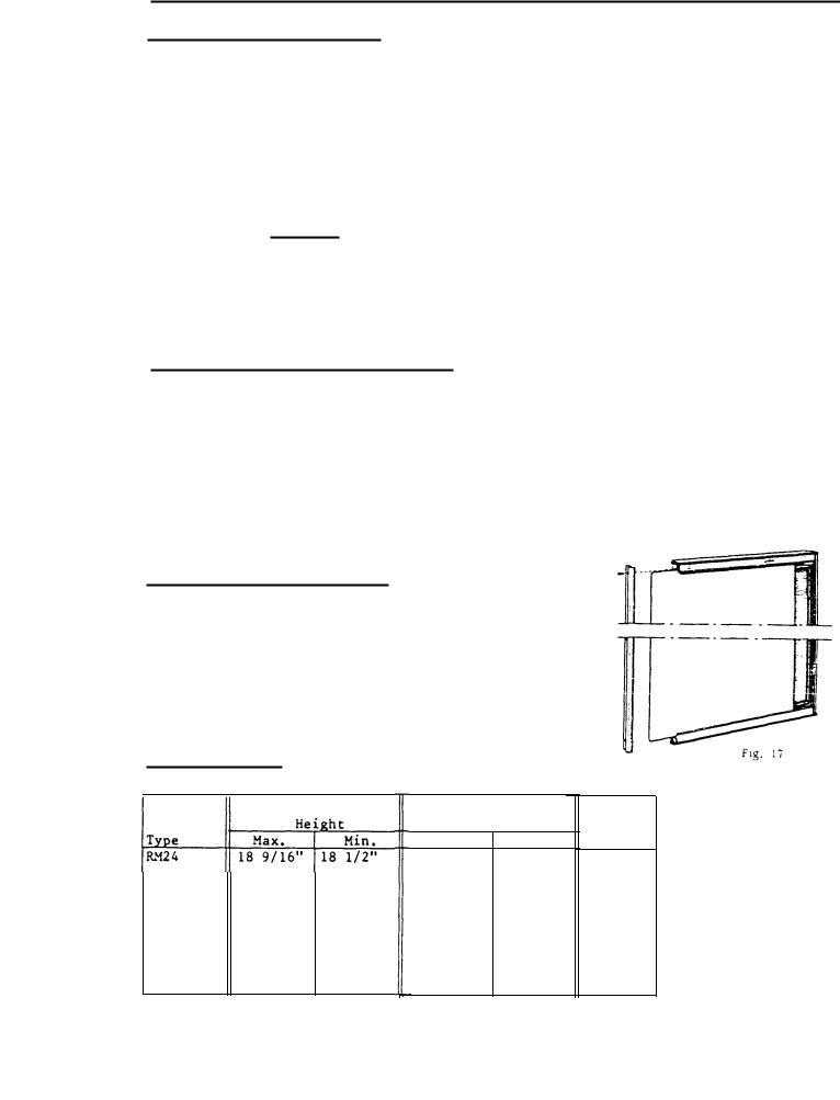
To change the door panel. Model RM24.
A.Remove the top decoration strip (2) with its two screws (1). pull outward on the top of the door panel and lift slightly to free the panel from the bottom groove.
B. If a |
new panel is being installed, |
a s s u r e that it is the same size as |
|
the |
old panel, |
c . Install the new panel by inserting one of the vertical sides of the panel into the groove of the door frame (4).
D.Bend the panel gently so that the free side of the panel can be slipped into corresponding groove of the door frame (5).
E.Push the panel downwards so that the
lower horizontal |
edge of |
the panel |
is fitted in the |
bottom |
groove (6). |
F. Between the upper edge of the panel and the door frame there is now
a gap which should be covered by the decoration strip,
G.Put the strip across the door so that the gap is covered and push it upwards (7). The tabs on the inside of the strip should fit in behind the flange of the door frame.
H.When put in place, secure the decoration strip by means of the two
screws (1). |
The panel is then locked |
in proper |
position. |

15
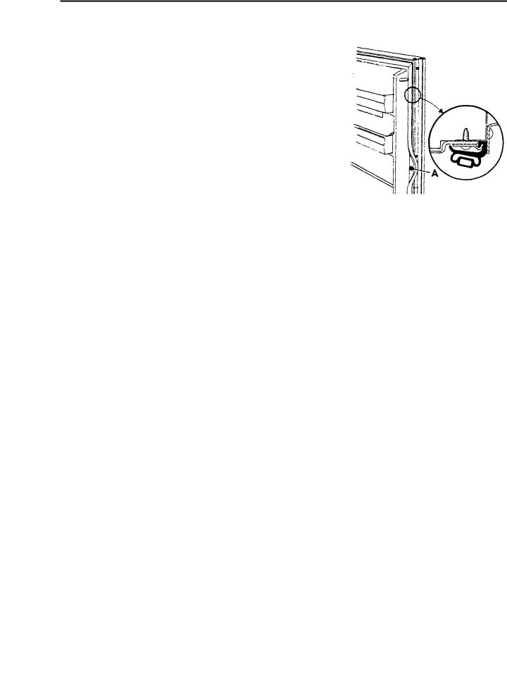
5. REPLACEMENT OF DOOR GASKET ON RM24
The construction of the door complete is an aluminium extruded door frame foamed in place with the door pan and magnetic door gasket, i.e. the door pan cannot be removed,
Therefore, |
a special door sealing gasket for |
service purposes |
has been produced |
for |
||||
the |
above model. The gasket is delivered in |
a set consisting |
of the gasket and of |
|||||
necessary fastening strips and s c r e w s and is |
ordered under |
part No. 290 07 33-00/3. |
||||||
The replacement is made as follows: |
|
|
|
|
|
|
||
1. |
Remove the door and place it with its front downwards on a soft surface. |
|
|
|||||
2. |
Cut off |
the defective door sealing gasket, |
(Cut as near |
to the |
door pan |
as |
|
|
|
p o s s i b l e ) . |
|
|
|
|
|
|
|
3. |
Drill 7/64” holes for the screws of the |
fastening strips. Use |
the holes |
of |
the |
|||
|
door pan as pattern. |
|
|
|
|
|
|
|
4. |
Fit the sealing gasket as shown in the |
figure 21. |
|
|
|
|
||
5, |
Fit the |
door and adjust it so that it seals |
properly. |
|
|
|
|
|
Fig. 21
16
Replacement of door gasket on models
RM36C, RM46, RM47, RM66, RM67, RM76, RM77
1.Remove the door shelves.
2.Unscrew the upper hinge bolt, incline the door outwards and lift off the door.
3.Lay door on flat surface with door pan facing up.
CAUTION: Be sure to protect door panel to prevent scratches and dents.
4.The screws holding the door pan in place are hidden by the door gasket. Pull the door
gasket to |
one |
side |
and |
remove all screws "A" |
Fig. 24 |
(see fig. |
24) |
from |
the |
door plate. |
|
6. REPLACEMENT OF EVAPORATOR DOOR ON RM36C
Unscrew the retainer (fig. 25) and remove the door.
REPLACEMENT OF EVAPORATOR DOOR CASKET - RM36C
1.Put evaporator door on a flat surface vith the sealing gasket up,
2.Pry the door front away from the inner pan by means of a screwdriver (fig. 26).
 Loading...