


DN-S3700

Ver. 1
SERVICE MANUAL
MODEL JP E3 E2 EK E2A E2C E1K EUT
DN-S3700
33
CD/USB MEDIA PLAYER & CONTROLLER
●
For purposes of improvement, specifications and design are subject to change without notice.
●
Please use this service manual with referring to the operating instructions without fail.
●
Some illustrations using in this service manual are slightly different from the actual set.
PROFESSIONAL BUSINESS COMPANY
X0408 V.01 DE/CDM 0901
SAFETY PRECAUTIONS
The following check should be performed for the continued protection of the customer and service technician.
LEAKAGE CURRENT CHECK
Before returning the unit to the customer, make sure you make either (1) a leakage current check or (2) a line to chassis
resistance check. If the leakage current exceeds 0.5 milliamps, or if the resistance from chassis to either side of the
power cord is less than 460 kohms, the unit is defective.
LASER RADIATION
Do not stare into beam or view directly with optical instruments, class 3A laser product.
CAUTION
Please heed the points listed below during servicing and inspection.
◎ Heed the cautions!
Spots requiring particular attention when servicing, such
as the cabinet, parts, chassis, etc., have cautions indicated
on labels or seals. Be sure to heed these cautions and the
cautions indicated in the handling instructions.
◎ Caution concerning electric shock!
(1) An AC voltage is impressed on this set, so touching in-
ternal metal parts when the set is energized could
cause electric shock. Take care to avoid electric shock,
by for example using an isolating transformer and
gloves when servicing while the set is energized, unplugging the power cord when replacing parts, etc.
(2)There are high voltage parts inside. Handle with extra
care when the set is energized.
◎ Caution concerning disassembly and
assembly!
Though great care is taken when manufacturing parts from
sheet metal, there may in some rare cases be burrs on the
edges of parts which could cause injury if fingers are
moved across them. Use gloves to protect your hands.
◎ Inspect for safety after servicing!
Check that all screws, parts and wires removed or disconnected for servicing have been put back in their original positions, inspect that no parts around the area that has been
serviced have been negatively affected, conduct an insulation check on the external metal connectors and between
the blades of the power plug, and otherwise check that
safety is ensured.
(Insulation check procedure)
Unplug the power cord from the power outlet, disconnect
the antenna, plugs, etc., and turn the power switch on. Using a 500V insulation resistance tester, check that the insulation resistance between the terminals of the power
plug and the externally exposed metal parts (antenna terminal, headphones terminal, microphone terminal, input
terminal, etc.) is 1MΩ or greater. If it is less, the set must
be inspected and repaired.
CAUTION
Concerning important safety
parts
◎ Only use designated parts!
The set's parts have specific safety properties (fire resistance, voltage resistance, etc.). For replacement parts, be
sure to use parts which have the same properties. In particular, for the important safety parts that are marked z on
wiring diagrams and parts lists, be sure to use the designated parts.
◎ Be sure to mount parts and arrange
the wires as they were originally!
For safety reasons, some parts use tape, tubes or other insulating materials, and some parts are mounted away from
the surface of printed circuit boards. Care is also taken with
the positions of the wires inside and clamps are used to
keep wires away from heating and high voltage parts, so
be sure to set everything back as it was originally.
Many of the electric and structural parts used in the set
have special safety properties. In most cases these properties are difficult to distinguish by sight, and using replacement parts with higher ratings (rated power and
withstand voltage) does not necessarily guarantee that
safety performance will be preserved. Parts with safety
properties are indicated as shown below on the wiring diagrams and parts lists is this service manual. Be sure to replace them with parts with the designated part number.
(1) Schematic diagrams ... Indicated by the z mark.
(2) Parts lists ... Indicated by the z mark.
Using parts other than the designated
parts could result in electric shock, fires or
other dangerous situations.
2
DN-S3700
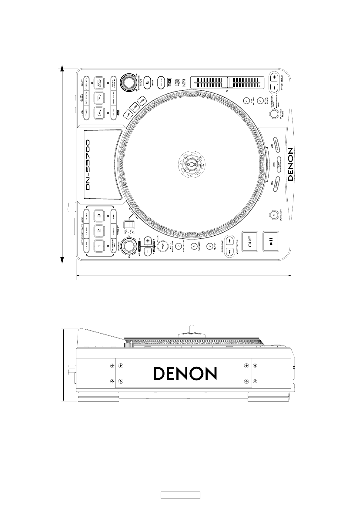
DIMENSION
3
DN-S3700
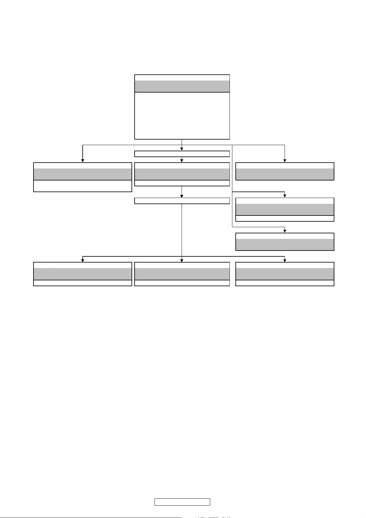
DISASSEMBLY
Y
T
T
Y
L
T
T
• Disassemble in order of the arrow of the figure of following flow.
• In the case of the re-assembling, assemble it in order of the reverse of the following flow.
• In the case of the re-assembling, observe "attention of assembling" it.
Refer to "DISASSEMBLY 1.TOP CASE ASSY"
FWD/BOTH UNIT
(Ref. No. of EXPLODED VIEW : F)
SLIDE VR UNIT
(Ref. No. of EXPLODED VIEW : G)
VFD UNIT (Ref. No. of EXPLODED VIEW : H)
PANEL1 UNIT (Ref. No. of EXPLODED VIEW : I)
PANEL2 UNIT (Ref. No. of EXPLODED VIEW : J)
PANEL3 UNIT (Ref. No. of EXPLODED VIEW : K)
and "EXPLODED VIEW"
SHIELD PLATE
TOP CASE ASS
Refer to "DISASSEMBLY 6.MOTORDRIVE UNIT" Refer to "DISASSEMBLY 2.MAIN UNIT Refer to "DISASSEMBLY 7.CD MECHA UNIT"
MOTORDRIVE UNIT MAIN UNI
and "EXPLODED VIEW" and "EXPLODED VIEW" and "EXPLODED VIEW"
MOTORDRIVE UNIT MAIN UNIT (Ref. No. of EXPLODED VIEW : D)
(Ref. No. of EXPLODED VIEW : L)
CHASSIS STA
Refer to "DISASSEMBLY 8.CD IN UNIT"
CD IN UNIT (Ref. No. of EXPLODED VIEW : E)
CD MECHA UNI
CD IN UNIT
and "EXPLODED VIEW"
FRONT SUB PANE
Refer to "DISASSEMBLY 9.FRONT SUB PANEL"
and "EXPLODED VIEW"
Refer to "DISASSEMBLY 3.AC INPUT UNIT" Refer to "DISASSEMBLY 4.AUDIO UNIT" Refer to "DISASSEMBLY 5.POWER UNIT"
AC INPUT UNI
and "EXPLODED VIEW" and "EXPLODED VIEW" and "EXPLODED VIEW"
AC INLET UNIT (Ref. No. of EXPLODED VIEW : B) AUDIO UNIT (Ref. No. of EXPLODED VIEW : C) POWER UNIT (Ref. No. of EXPLODED VIEW : A)
AUDIO UNI
POWER UNIT
4
DN-S3700
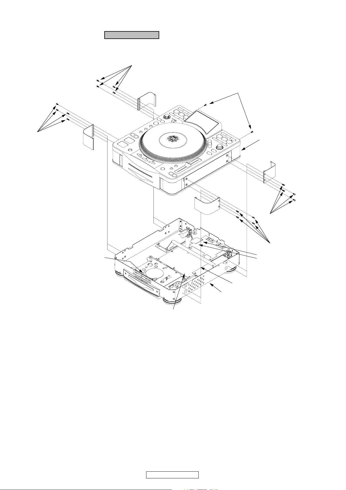
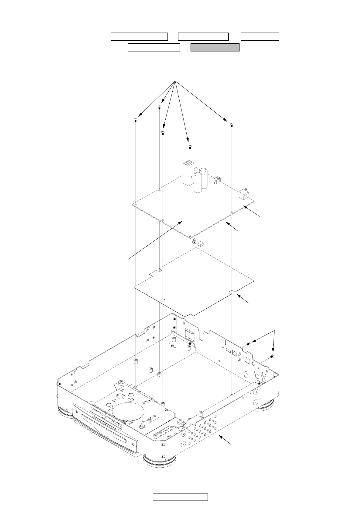
1. TOP CASE ASSY
Proceeding : TOP CASE ASSY
(1) Remove the screws and disconnect the FFC CABLE and connector wires.
SCREWS
SCREWS
SCREWS
4P CONNECTOR WIRE ( CX043 )
TOP CASE ASSY
SCREWS
SCREWS
15P FFC CABLE ( CX151 )
7P FFC CABLE ( CX072 )
12P CONNECTOR WIRE ( CX121 )
MAIN CHASSIS ASSY
Front side
4P CONNECTOR WIRE ( CX044 )
DN-S3700
5

(2) Pull out the KNOBs and remove the screws.
TOP SHIELD
PANEL 2 UNIT
SCREWS
BRACKET
SCREWS
SCREWS
PANEL 3 UNIT
TOP CASE ASSY
SLIDE VR UNIT
FWD/BOTH UNIT
PANEL 1 UNIT
KNOB
SELECT KNOB ASSY
FADER KNOB
6
DN-S3700
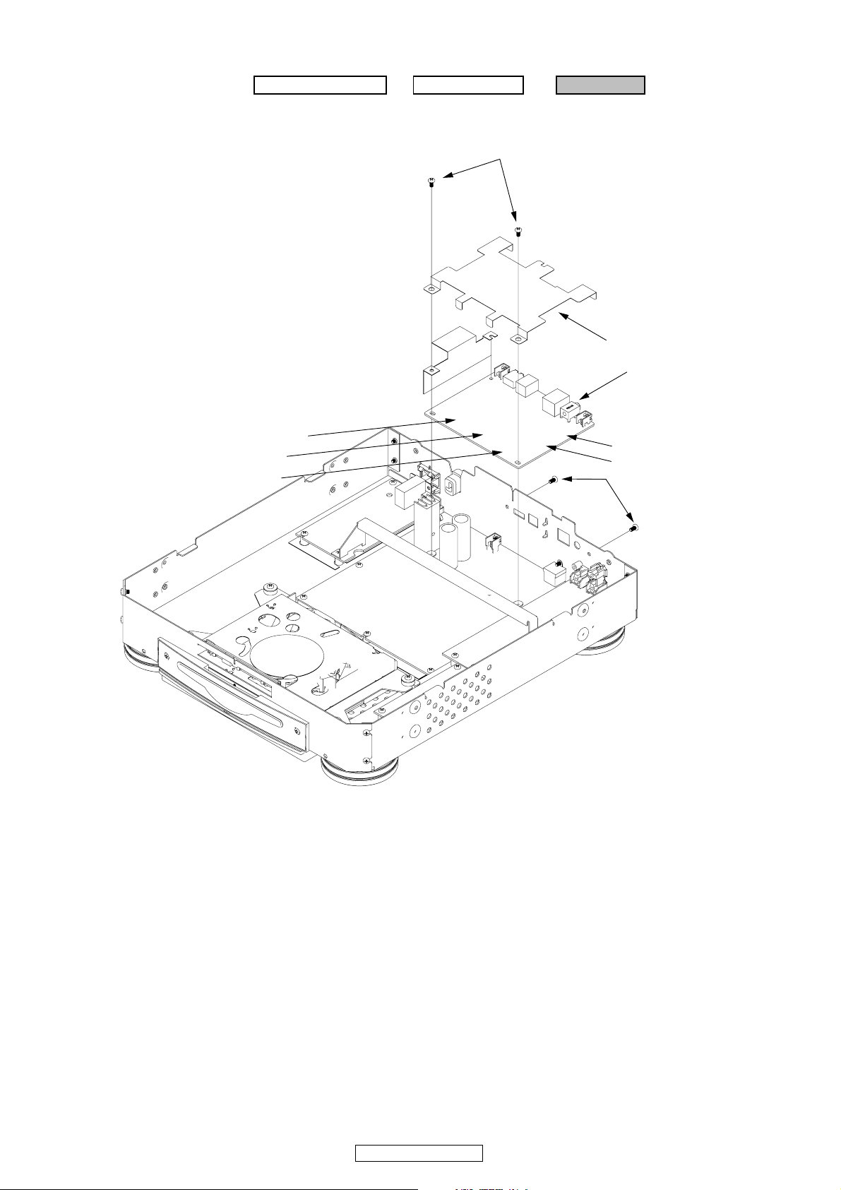
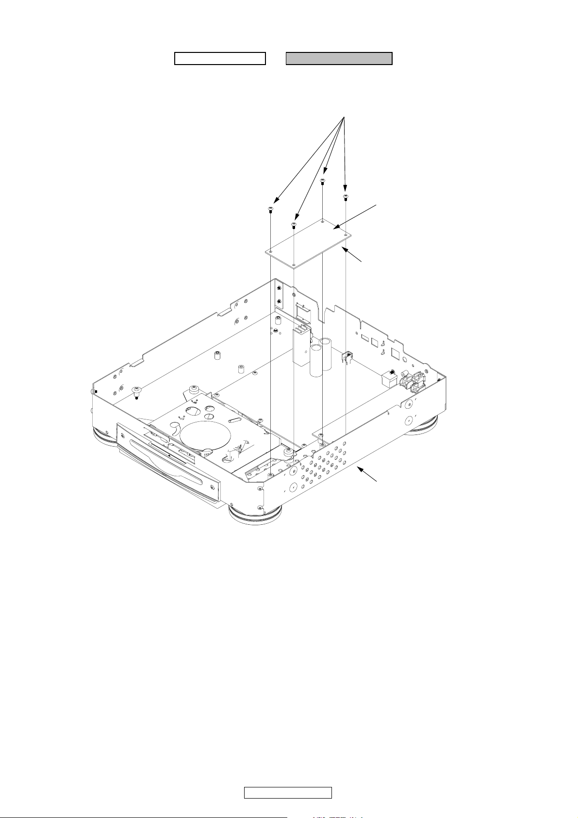
2. MAIN UNIT
Proceeding : TOP CASE ASSY → SHILD PLATE → MAIN UNIT
(1) Disconnect the FFC CABLE and connector wires and remove the screws.
SCREWS
SHIELD PLATE
MAIN UNIT
24P FFC CABLE ( CX241 )
22P FFC CABLE ( CX221 )
7P CONNECTOR WIRE ( CX071 )
18P FFC CABLE ( CX181 )
11P FFC CABLE ( CX112 )
SCREWS
7
DN-S3700
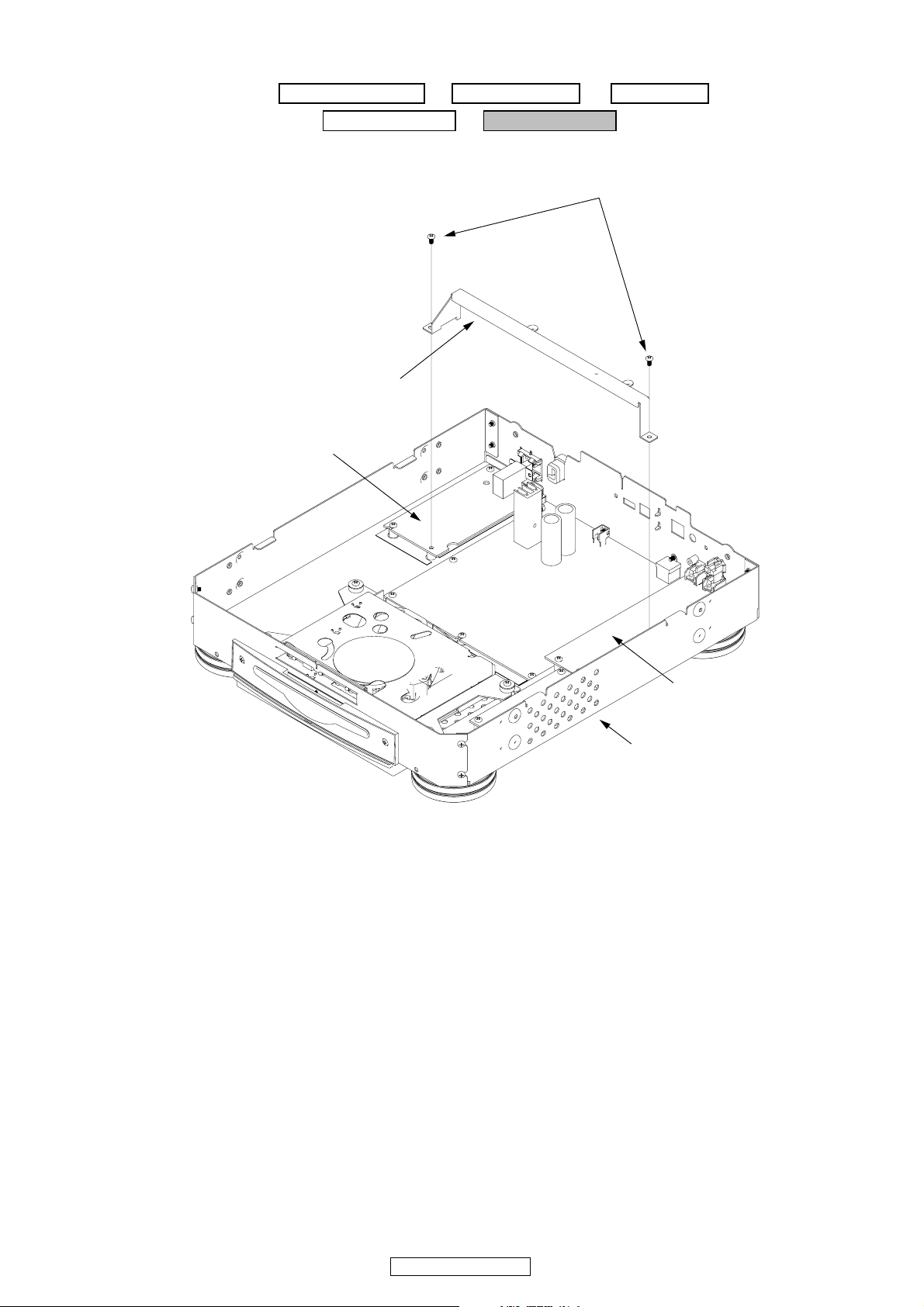
3. AC INPUT UNIT
Proceeding : TOP CASE ASSY → SHIELD PLATE → MAIN UNIT
→ CHASSIS STAY → AC INPUT UNIT
(1) Remove the screws for CHASSIS STAY.
SCREWS
CHASSIS STAY
AC INPUT UNIT
Rear side
AUDIO UNIT
MAIN CHASSIS ASSY
8
DN-S3700
(2) Disconnect the connector wire and remove the screws.
AC INPUT UNIT
2P CONNECTOR WIRE ( CY022 )
SCREWS
CORD BUSH
P.SW KNOB
INSULATION SHEET ( AC INPUT )
P.SW KNOB GUIDE
MAIN CHASSIS ASSY
9
DN-S3700
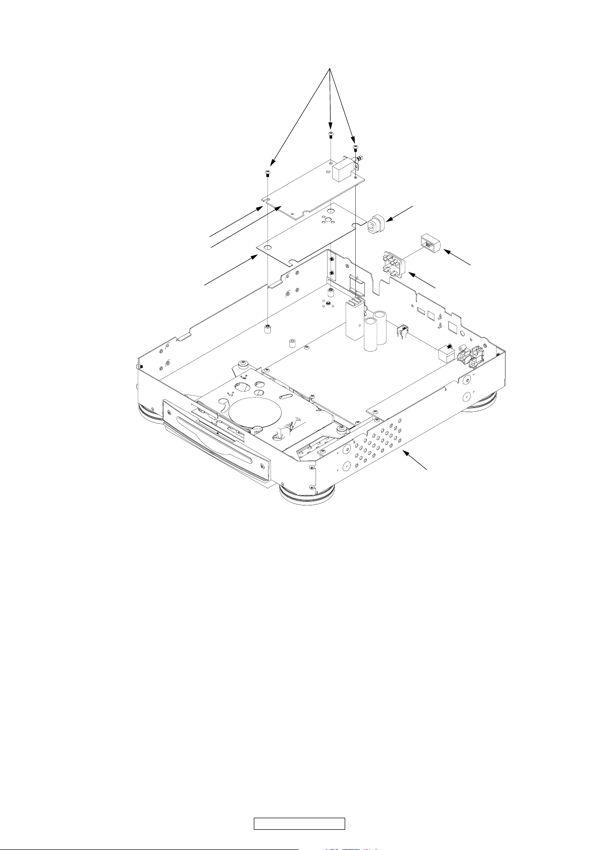
4. AUDIO UNIT
Proceeding : TOP CASE ASSY → SHIELD PLATE → MAIN UNIT
→ CHASSIS STAY → AUDIO UNIT
(1) Disconnect the FFC CABLE and connector wire and remove the screws.
SCREWS
9P CONNECTOR WIRE ( CY091 )
AUDIO UNIT
11P FFC CABLE ( CY112 )
SCREWS
Rear Side
POWER UNIT
MAIN CHASSIS ASSY
10
DN-S3700
5. POWER UNIT
Proceeding : TOP CASE ASSY → SHIELD PLATE → MAIN UNIT
→ CHASSIS STAY → POWER UNIT
(1) Disconnect the FFC CABLE and connector wire and remove the screws.
SCREWS
14P CONNECTOR WIRE ( CX141 )
18P FFC CABLE ( CY181 )
POWER UNIT
INSULATION SHEET ( POWER )
Rear Side
SCREWS
11
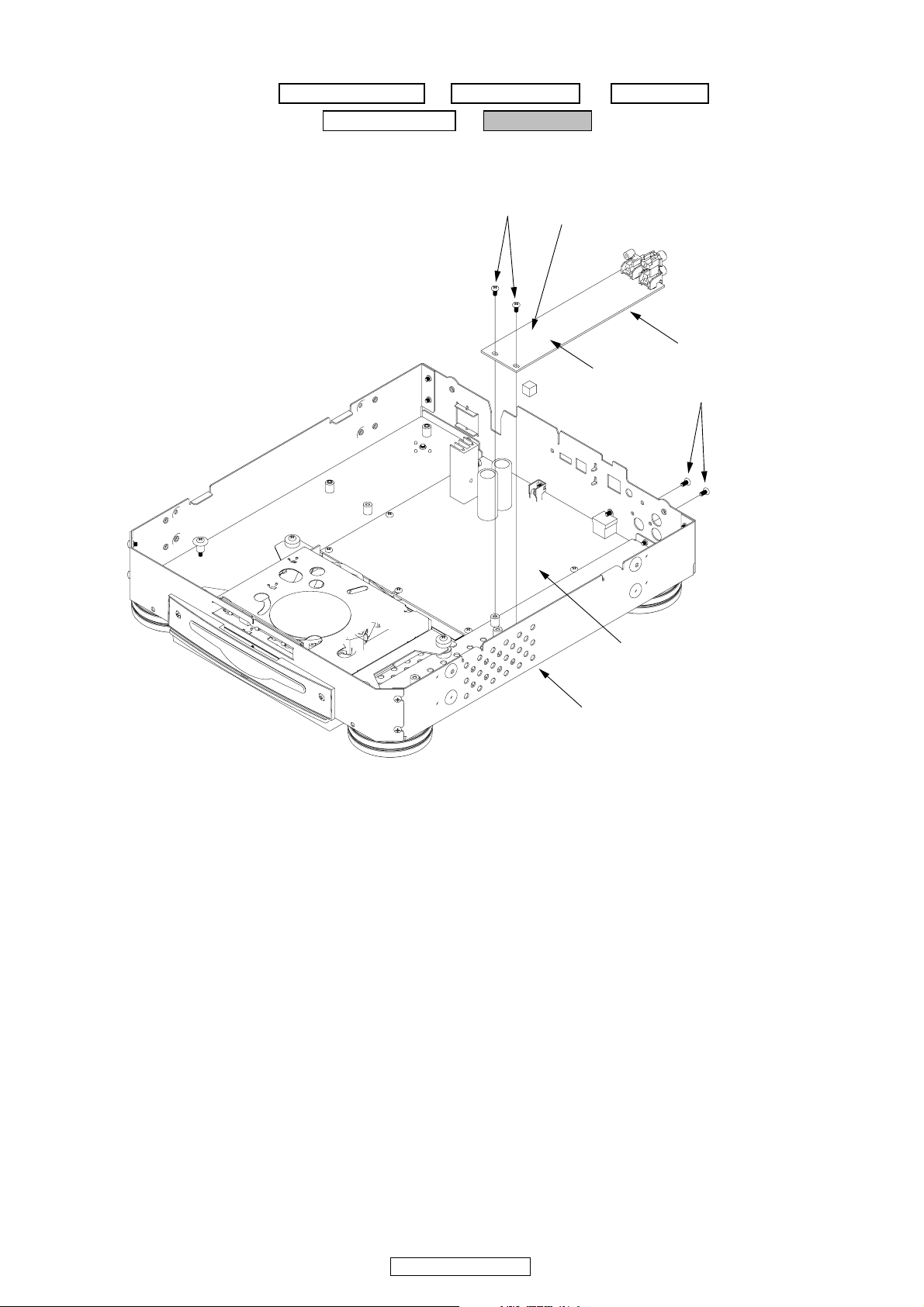
DN-S3700
MAIN CHASSIS ASSY
6. MOTORDRIVE UNIT
Proceeding : TOP CASE ASSY → MOTORDRIVE UNIT
(1) Disconnect the connector wire and remove the screws.
SCREWS
14P CONNECTOR WIRE ( CY141 )
MOTORDRIVE UNIT
Rear Side
MAIN CHASSIS ASSY
12
DN-S3700
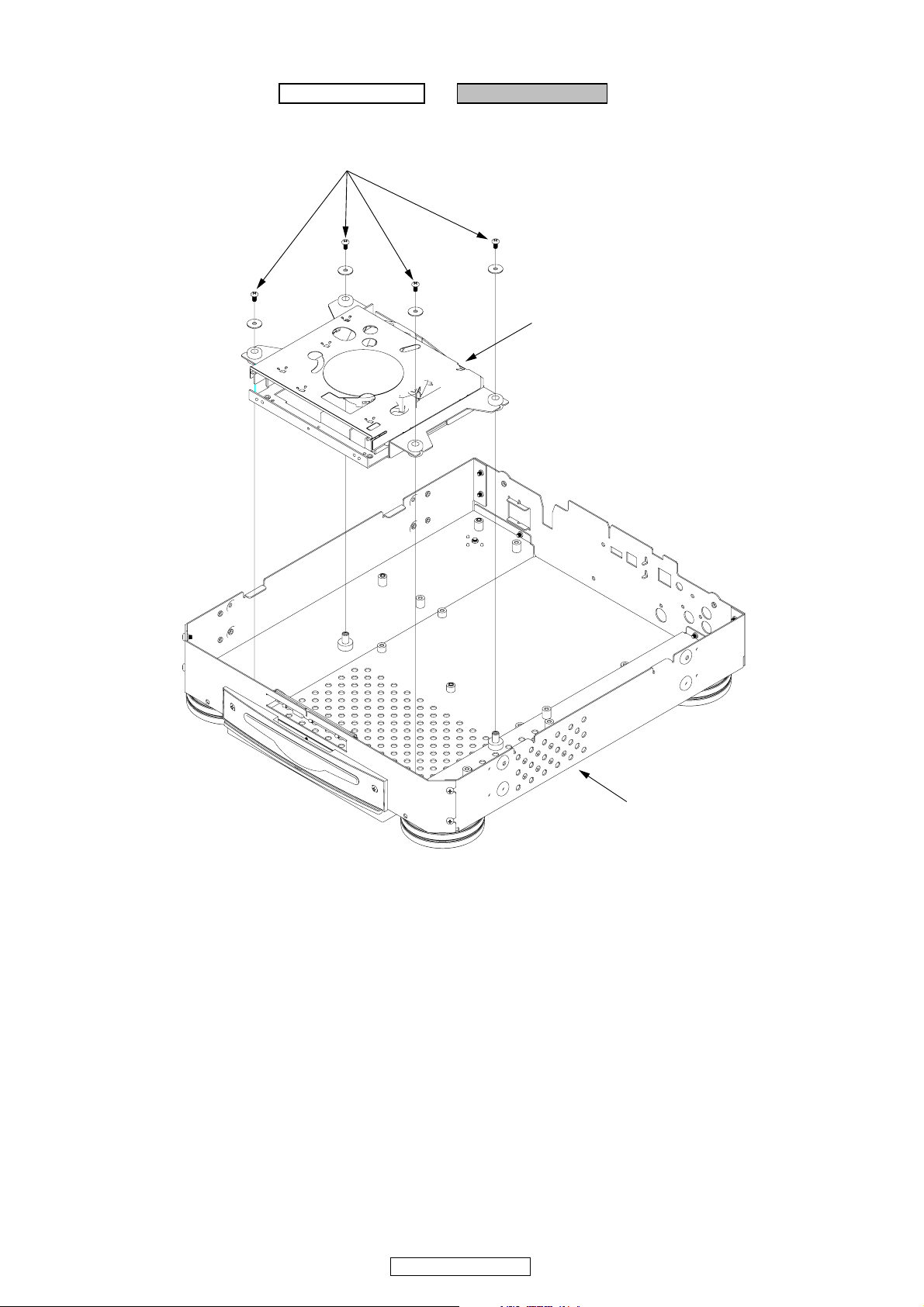
7. CD MECHA UNIT
Proceeding : TOP CASE ASSY → CD MECHA UNIT
(1) Remove the screws.
SCREWS
CD MECHA. UNIT
Rear Side
MAIN CHASSIS ASSY
13
DN-S3700

8. CD IN UNIT
Proceeding : TOP CASE ASSY → CD IN UNIT
(1) Remove the screws.
Rear side
SCREWS
MAIN CHASSIS ASSY
CD IN UNIT
14
DN-S3700
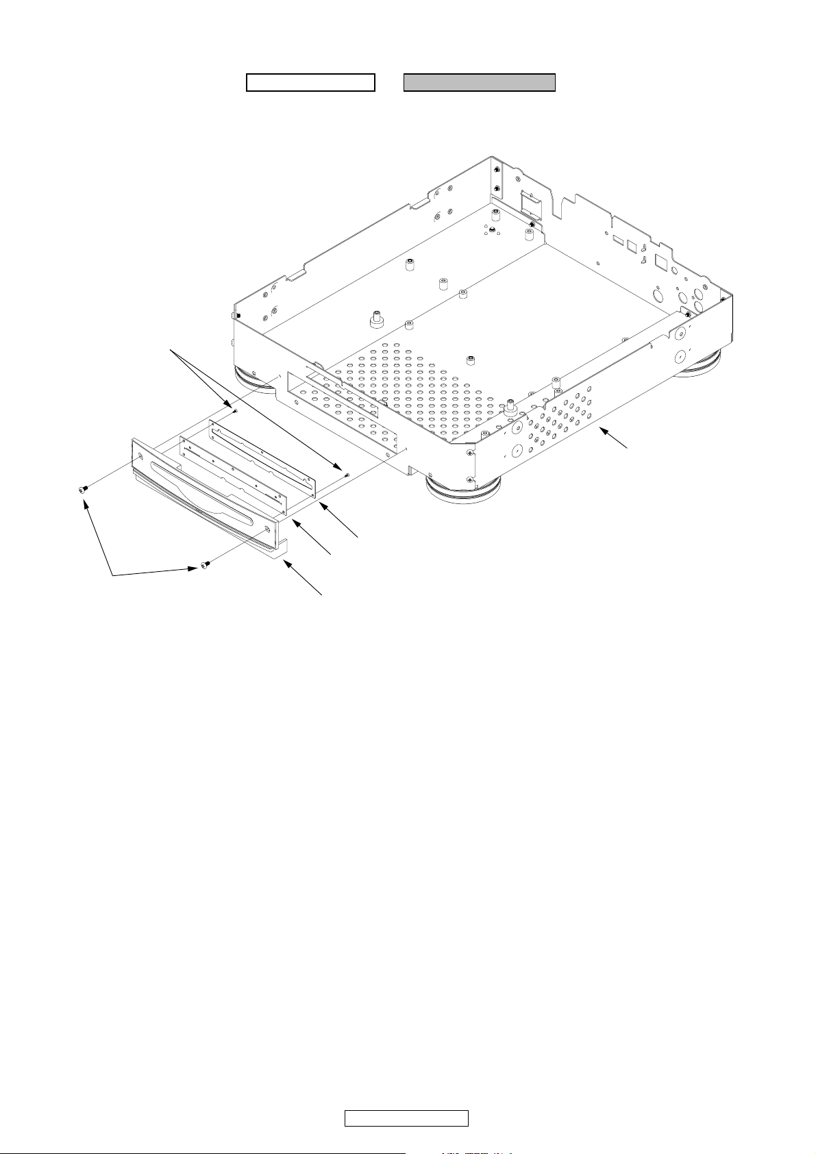
9. FRONT SUB PANEL
Proceeding : TOP CASE ASSY → FRONT SUB PANEL
(1) Remove the screws.
SCREWS
Rear Side
SCREWS
MAIN CHASSIS ASSY
BRACKET ( CD MASK )
CD MASK
FRONT SUB PANEL
15
DN-S3700

SERVICE MODE
Function summary
1. SERVICE MODE
(1) Top level of the service mode
2. Checking the operations of the functions (Function CHK)
(1) Setting initialization (S3700 init)
(2) D-Link operation check (D-Link Check)
(3) Audio signal output (Audio Out)
(4) Audio mute check (Mute Check)
(5) USB device operation check (USB Test)
(6) PS/2 operation check (PS/2 Check)
3. Checking the operations of the CD drive (CD Drive CHK)
(1) Disk type distinction display (Disc Type)
(2) Servo data display (Servo Data)
(3) Error rate display (Error Rate)
(4) Pickup movement (PU Clean)
(5) Remove the disc (Loader Clean)
(6) Error code display (Err Code CHK)
(7) Total running time display (Total Time)
(8) Heat Run mode1 (H/R1)
(9) Heat Run mode2 (H/R2)
4. Checking the operations of the switches (SW Check)
5. Checking the operations of the panel (Panel CHK)
(1) PARAMETERS knob
(2) EFFECTS knob
(3) PITCH SLIDER
(4) FADER IN
The functions shown below are always available while in the panel check mode.
(5) All lit / DIM lit / All off
6. Checking the rotation pulse detection of the JOG disc (JOG CHK)
(1) Platter jog disc rotation direction/rotation pulse number
(2) Turntable rotation direction/rotation pulse number
7. Checking the rotation speed of the platter (PLATTER CHK)
8. Version upgrade procedure of firmware
16
DN-S3700
1. SERVICE MODE
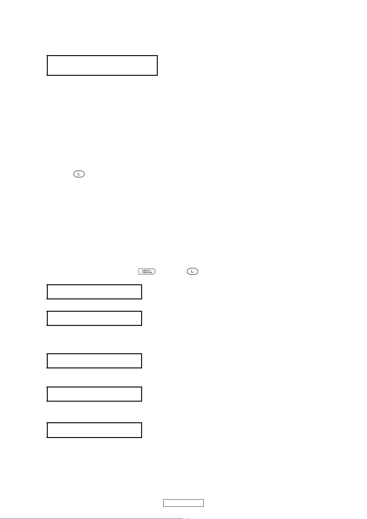
1.1. Top level of the service mode (Turning on the power in the service mode)
(1) Turn on the power while pressing the PARAMETERS knob and the button simultaneously.
The following appears on the VFD dot display section:
--
Service Mode
Function CHK
(2) When the PARAMETERS knob is turned clockwise, the display on the second row of the VFD dot display section
switches in the following order: "Function CHK" → "CD Drive CHK" → "SW Check" → "Panel CHK" → "JOG CHK" →
"PLATTER CHK".
The display switches in the opposite order when the PARAMETERS knob is turned counterclockwise.
(3) The displayed mode can be selected by pressing the PARAMETERS knob.
--
2. Checking the operations of the functions (Function CHK)
(1) Turn the PARAMETERS knob to select "Function CHK" from the service mode's top menu, then press the PARAME-
TERS knob to set the function check mode. The following appears on the VFD dot display section:
Function CHK
S3700 init
(2) When the PARAMETERS knob is turned clockwise, the display on the second row of the VFD dot display section switch-
es in the following order: "S3700 init" → "D-Link Check" → "Audio Out" → "Mute Check" → "USB Test" → "PS/2 Check".
The display switches in the opposite order when the PARAMETERS knob is turned counterclockwise.
(3) The displayed mode can be executed by pressing the PARAMETERS knob.
(4) Press the button to return to the top level of the service mode.
2.1. Setting initialization (S3700 init)
• The contents of the preset memory are set to the factory defaults
(1) Turn the PARAMETERS knob to select "S3700 init" from the “Function CHK” mode's top menu, then press the PARAM-
ETERS knob to set "S3700 init" mode. The following appears on the VFD dot display section:
Function CHK
S3700 init
(2) The Initialization mode can be executed by pressing the PARAMETERS knob. The following appears on the second
row of the VFD dot display section:
When initialization is completed:
Complete!
When initialization is not completed (Time out):
Fail
(3) Press the button to return to the top level of the function check mode.
2.2. D-Link operation check (D-Link Check)
• When executed with the D-Link terminal's Tx and Rx pins connected externally, the loop-back test is performed.
• The device checks whether the transferred and received contents are the same and the results are displayed.
(1) Turn the PARAMETERS knob to select "D-Link Check" from the “Function CHK” mode's top menu, then press the PA-
RAMETERS knob to set "D-Link Check" mode. The following appears on the VFD dot display section:
D-Link Check.
Exec to push.
(2) The displayed mode can be executed by pressing the PARAMETERS knob. The following appears on the second row
of the VFD dot display section:
When the process has completed normally:
Complete!
When the process has completed abnormally:
Fail
(3) Press the button to return to the top level of the function check mode.
17
DN-S3700
2.3. Audio signal output (Audio OUT)
• The device's built-in 24 bit/44.1 kHz sampling frequency audio signals are played from ADSP.
(1) Turn the PARAMETERS knob to select "Audio OUT" from the “Function CHK” mode's top menu, then press the PA-
RAMETERS knob to set "Audio OUT" mode.
Information on the operations is displayed on the first row of the VFD dot display, information on the output signal on
the second row.
(2) Turn the PARAMETERS knob clockwise and display the signal to be output from q to o on the VFD dot display.
Press the PARAMETERS knob while the signal to be output is displayed to set it. The selected signal is output from
ADSP.
q 1kHz -6dBFS signals are output from the left and right channels.
Reference
1kHz -6dBFS
w 1kHz 0dBFS signals are output from the left and right channels.
Max Level
1kHz 0dBFS
e 20Hz -6dBFS signals are output from the left and right channels.
Freq.
20kHz -6dBFS
r 1kHz -6dBFS signals are output from the left and right channels.
Freq. Chara.
1kHz
t 20kHz -6dBFS signals are output from the left and right channels.
Freq. Chara.
20kHz -6dBFS
Chara.
-6dBFS
y 1kHz - ∞ dBFS signals are output from the left and right channels.
Infinity
u 1kHz -6dBFS signals are output from the left and right channels.
Reference
1kHz -6dBFS
i 1kHz -6dBFS signals are output from the left channel.
- ∞ dBFS signals are output from the right channel.
Cross Talk R
L:1kHz -6dBFS
o 1kHz -6dBFS signals are output from the right channel.
- ∞ dBFS signals are output from the left channel.
Cross
R:1kHz -6dBFS
(3) Press the button to return to the top level of the function check mode.
Talk L
0
2.4. Audio Mute check (Mute Check)
• Switches the hardware's muting circuit on and off.
• Output a 1 kHz/0 dB audio signal from ADSP for both the left and right channels. (Use the [2.3 Audio signal output] sig-
nal.)
(1) Turn the PARAMETERS knob to select "
RAMETERS knob to set "
The current muting status is displayed on the VFD dot display.
Mute
or
Check
OFF
Mute Check
Mute Check
" mode.
" from the “Function CHK” mode's top menu, then press the PA-
Mute Check
(2) Turn the PARAMETERS knob clockwise to select "ON", counterclockwise to select "OFF" the mute control mode status.
(3) Press the button to return to the top level of the function check mode.
ON
18
DN-S3700

2.5. USB device operation check (USB Test)
• Use this procedure to test data writing on the device connected to the USB-A connector.
(1) Turn the PARAMETERS knob to select "USB Test" from the “Function CHK” mode's top menu, then press the PARAM-
ETERS knob to set "USB Test" mode. The following appears on the VFD dot display section:
PUSH Param.
(2) The displayed mode can be executed by pressing the PARAMETERS knob. The following appearson the second row
of the VFD dot display section:
Now Testing
When the USB device is not connected:
(3) The test is completed, the following appears on the second row of the VFD dot display section:
When the process has completed normally:
When the process has completed abnormally:
(4) Press the button to return to the top level of the function check mode.
USB TEST
Fail
Complete!
Fail
2.6. PS/2 operation check (PS/2 Check)
• The PS /2 keyboard are set to the factory defaults.
(1) When a PS/2 keyboard is connected, turn the PARAMETERS knob to select "PS/2 Check" from the “Function CHK”
mode's top menu, then press the PARAMETERS knob to set "PS/2 Check" mode. The following appears on the VFD
dot display section:
PUSH PARAM
KB Init.
(2) The displayed mode can be executed by pressing the PARAMETERS knob. The following appears on the VFD dot dis-
play section (The the second row is cleared):
KB Init OK
When the keyboard is not connected, the following appears on the VFD dot display section (The the second row is
cleared):
KB Init Fail
(3) When a key on the keyboard is pressed, the key that was pressed is displayed on the second row of the VFD dot display
(A to Z, 0 to 9).
(4) Press the button to return to the top level of the function check mode.
19
DN-S3700
3. Checking the operations of the CD drive (CD Drive CHK)
(1) Turn the PARAMETERS knob to select "CD Drive CHK" from the service mode's top menu, then press the PARAME-
TERS knob to set the function check mode. The following appears on the VFD dot display section:
--
Service Mode
CD Drive CHK
(2) When the PARAMETERS knob is turned clockwise, the display on the second row of the VFD dot display section switch-
es in the following order: "Disc Type" → "Servo Data" → "Error Rate" → "PU Clean" → "Loader Clean" → "ErrorCode
CHK" → "Total Time" → "H/R1" → "H/R2". The display switches in the opposite order when the PARAMETERS knob is
turned counterclockwise.
(3) The displayed mode can be executed by pressing the PARAMETERS knob.
(4) Press the button to return to the top level of the service mode.
3.1. Disk type distinction display (Disc Type)
(1) Turn the PARAMETERS knob to select "Disc Type" from the “CD Drive CHK” mode's top menu, then press the PARAM-
ETERS knob to set "Disc Type" mode.
(2) The currently loaded disc is identified, and "No Disc", "CD-DA/ROM", "CD-RW" or "Unknown" is displayed on the sec-
ond row of the VFD dot display.
(3) Press the button to return to the top level of the CD Drive check mode.
3.2. Servo data display (Servo Data)
• The automatic adjustment value of the servo is displayed.
(1) Turn the PARAMETERS knob to select "Servo Data" from the “CD Drive CHK” mode's top menu, then press the PA-
RAMETERS knob to set "Servo Data" mode.
(2) When the PARAMETERS knob is turned clockwise, the display item is displayed on the first row of the VFD dot display,
the data on the second row, switching in the order q to Q5. The display switches in the opposite order when the PA-
RAMETERS knob is turned counterclockwise.
q "Fo Gain" (Focus gain data)
w "Fo Balance" (Focus balance data)
e "Fo Offset" (Focus offset data)
r "Fo D.AC/BD" (Focus digital AC/BD data)
t "Fo A.AC/BD" (Analog AC/BD data of focus)
y "Tr Gain" (Tracking gain data)
u "Tr Balance" (Tracking balance data)
i "Tr Offset" (Tracking offset data)
o "Tr D.AC/BD (Tracking digital AC/BD data)
Q0 "Tr A.AC/BD" (Analog AC/BD data of tracking)
Q1 "SD Offset" (SD offset data)
Q2 "RF Offset" (RF offset data)
Q3 "RF Gain" (RF gain data)
Q4 "VCO Offset" (VCO offset data)
Q5 "VCO Gain" (VCO gain data)
(3) With q to Q5 selected, press the 5 button to eject the disc, then reload the disc for readjust the servo.
(4) Press the button to return to the top level of the CD Drive check mode.
--
3.3. Error rate display (Error Rate)
• The error rate of C2 is displayed.
(1) Turn the PARAMETERS knob to select "Error Rate" from the "CD Drive CHK" mode's top menu, then press the PA-
RAMETERS knob to set "Error Rate" mode.
(2) Play a CD and display the total number of C2 errors per second.
(3) "TOC Reading" is displayed on the second row of the VFD dot display if the CD's TOC has not yet been read.
(4) When the TOC has been read, "C2-ERR" is displayed on the first row of the VFD dot display, and the total number of
C2 errors per second is displayed on the second row.
(5) Press the Quick Jump button to perform the track search operation.
(6) Press the button to return to the top level of the CD Drive check mode.
20
DN-S3700
3.4. Pickup movement (PU Clean)
• Move the pickup lens to any position.
(1) Turn the PARAMETERS knob to select "PU Clean" from the "CD Drive CHK" mode's top menu, then press the PA-
RAMETERS knob to set "PU Clean" mode. The following appears on the VFD dot display section:
PU Clean
PUSH BEND+&-
(2) Press the PITCH BEND button to move the pickup lens. The pickup lens stops moving when the PITCH BEND button
is released.( button: Direction of outer / button: Direction of inner)
(3) Press the button to return to the top level of the CD Drive check mode.
3.5. Remove the disc (Loader Clean)
• Turn the loading motor in the direction of disc ejection.
(1) Turn the PARAMETERS knob to select "Loader Clean" from the "CD Drive CHK" mode's top menu, then press the
PARAMETERS knob to set "Loader Clean" mode. The following appears on the VFD dot display section:
Loader Clean
PUSH SEARCH+
(2) Press the button and turn the loading motor in the direction of disc ejection. The motor stops turning when the
button is released.
(3) Press the button to return to the top level of the CD Drive check mode.
3.6. Error code display (Error Code CHK)
(1) Turn the PARAMETERS knob to select "Error Code CHK" from the "CD Drive CHK" mode's top menu, then press the
PARAMETERS knob to set "Error Code CHK" mode. The following appears on the VFD dot display section:
Error
Data
XX_EYYY
(XX:Error logging number, EYYY:Error code, not error:turn off)
(2) Up to 10 errors occurring in the CD mode are stored in the MEMO memory.
※ The errors remain stored in the memory until they are cleared, and once they are cleared up to 10 new errors are
stored.
(3) Turn the PARAMETERS knob to check the error logging data.
When the PARAMETERS knob is pressed, "Error Clear?" is displayed on the second row of the VFD dot display. When
the PARAMETERS knob is pressed again at this time, all the data is cleared. Turn the PARAMETERS knob to cancel.
(4) Error code table
Error code Error contents
E204 Focus servo dropped during cuing.
E205 Focus servo dropped during pausing
E206 Focus servo dropped during manual searching or scanning.
E213 Subcode could no longer be read in the cue mode
E214 Subcode could no longer be read in the pause mode.
E215
Focus servo dropped during manual searching or scanning.
21
DN-S3700

3.7. Total running time display (Total Time)
(1) Turn the PARAMETERS knob to select "Total Time" from the "CD Drive CHK" mode's top menu, then press the PA-
RAMETERS knob to set "Total Time" mode. The following appears on the VFD dot display section:
Total Time
XXXXXh
(XXXXX:Total running time, Time [h])
(2)
When the PARAMETERS knob is pushed, it switches to the Total Time deletion mode.
The following appears on the VFD dot display section:
Time Clear
Cancel
(3) When the PARAMETERS knob is turned, the display on the second row of the VFD dot display section switches in the
"OK" or "Cancel".
(4) Display "OK", then press the PARAMETERS knob to set. The total time is cleared and the display returns to as it was
in step (1).
(5) Display "Cancel", then press the PARAMETERS knob to set.
(6) Press the button to return to the top level of the CD Drive check mode.
The display returns to as it was in step (1).
3.8. Heat Run mode1 (H/R1)
(1) Turn the PARAMETERS knob to select "H/R1" from the "CD Drive CHK" mode's top menu.
When the disc is recognized, the following appears on the VFD dot display section:
HeatRun1
Push
When the disc is not recognized, or when the disc is not inserted, the following appears on the VFD dot display section:
Play
HeatRun1
Reading
(2) When the /13
The following appears on the second row of the VFD dot display section:
(XXXXX : Operation count)
(3) If disc being used has less than 20 tracks, play all tracks. If disc has 21 or more tracks, skip to final track after playback
of first track has finished.
(4) Once playback is completed, automatically eject and reload the disk and repeat the playback operation in step (3).
(5) When there is an error, The following appears on the second row of the VFD dot display section:
( XXXXX:
(6) To end the Heat Run1 mode, turn the power off.
button is pressed, Heat Run1 mode is started.
XXXX
E***
Operation count, E***:Error code)
XXXX
3.9. Heat Run mode1 (H/R2)
(1) Turn the PARAMETERS knob to select "H/R2" from the "CD Drive CHK" mode's top menu.
The following appears on the VFD dot display section:
HeatRun2
Push
(2) When disc is inserted the /13
he following appears on the second row of the VFD dot display section:
Play
button is pressed, first of Heat Run2 mode is started.
XXXX
(XXXXX : Operation count)
(3) The disc is drawn in, loading is performed and the TOC is read.
(4) Once reading of the TOC is completed, the disc is ejected and the eject operation is completed.
(5) The operation is repeated automatically from (3).
(6) When there is an error, The following appears on the second row of the VFD dot display section:
E***
( XXXXX:
(7) To end the Heat Run2 mode, turn the power off.
Operation count, E***:Error code)
XXXX
22
DN-S3700
3.10.Error code table
Error code Error contents
E100
E101 Tracking offset cannot be adjusted.
E102 Focus offset cannot be adjusted.
E103 Focus rough gain cannot be adjusted.
E104 Focus servo does not turn on/spindle is faulty.
E105 Tracking servo does not turn on.
E106 Tracking rough gain cannot be adjusted.
E200 Focus servo dropped during playback.
E201 Focus servo dropped during searching.
E202 Focus servo dropped during auto adjustment.
E203 Focus servo dropped during TOC reading.
E210 500 msec subode could not be read during playback.
E211 1 sec. subode could not be read during searching.
E212 500 msec subode could not be read during TOC reading.
E300 TOC could not be read within specified time.
E400 Disc holder did not close within specified time.
E401 Disc holder did not open within specified time.
E500 Slide error (inner circumference switch did not turn on within specified time).
E501 Search error (Slide error).
E502 Slide error (inner circumference switch did not turn on within specified time).
Disc cannot be detected.
E800 Track skipped while data being stored in memory and retrying was conducted as
specified, but continuous data storage was not possible (forced link mode set).
23
DN-S3700

4. Checking the operations of the switches (SW Check)
(1) Turn the PARAMETERS knob to select "SW Check" from the service mode's top menu, then press the PARAMETERS
knob to set the "SW Check" mode.
--
Service Mode
SW Check
(2) All the VFD characters are lights.
The following appears on the VFD dot display section.
FNE123 T B<>
CPD BDR J-+
(3) When each switch is pushed
Brake → Turn off the "B" in the sixth place of second row.
Dump → Turn off the "D" in the seventh place of second row.
Reverse → Turn off the "R" in the eighth place of second row.
Echo/Loop → Turn off the "1" in the fourth place of first row.
Flanger → Turn off the "2" in the fifth place of first row.
Filter → Turn off the "3" in the sixth place of first row.
Eject → Turn off the "N" in the second place of second row.
PLAYLIST → Turn off the "D" in the third place of second row.
Fast Search → Turn off the "<" and ">" in the eleventh and twelfth place of first row.
BACK → Turn off the "B" in the tenth place of first row.
PITCH BEND → Turn off the "-" and " +" in the eleventh and twelfth place of second row.
TITLE → Turn off the "T" in the eighth place of first row.
FLIP → Turn off the "F" in the first place of first row.
EXIT_RELOOP → Turn off the "E" in the third place of first row.
CUE, PLAY → Turn off the "C" and "P" in the first and second place of second row.
PLATTER MODE → Turn off the "J" in the first and tenth place of second row.
A → Turn off the "(A" .
B → Turn off the "B)" .
MEMO → Turn off the "MEMO".
PITCH → Turn off the "PITCH".
TAP → Turn off the "BPM".
KEY ADJUST → Turn off the "KEY ADJ.".
CD → Turn off the "CD" .
USB → Turn off the "USB" .
MIDI → Turn off the "MIDI" .
TIME → Turn off the "T." .
DISPLAY → Turn off the "ELAPSED" .
AUTO → Turn off the "KB" .
EXIT → Turn off the "WFM".
A/B TRIM → Turn off the "AAC".
NEXT TRACK → Turn off the "MP3".
- (EFECT) → Turn off the "WAV".
+ (EFECT) → Turn off the "AIFF".
1 → Tu
2 → Turn off the "2". (10's place of track no)
3 → Turn off the "3". (1's place of track no)
CLR1 → Turn off the "C1". (1's place of minutes' display)
CLR2 → Turn off the "C2". (1's place of seconds' display)
CLR3 → Turn off the "C3". (Frame display)
rn off the "1". (100's place of track no)
The following appears on the VFD dot display section.
--
Once all the switches have been pressed, The following appears on the VFD dot display section.
(4)
Complete!
Press
(5) Press the PARAMETERS knob return to the top layer in the service mode.
Param
24
DN-S3700
5. Checking the operation of the panel (Panel CHK)
(1) Turn the PARAMETERS knob to select "Panel CHK" from the service mode's top menu, then press the PARAMETERS
knob to set the "Panel CHK" mode.
The following appears on the VFD dot display section:
P
E
FW< BT
Other displays/indicators
(2) Display of the status and results of the various control elements on the panel surface and external input from the rear side.
PARAMETERS knob → Displays the "P" for the first place of the first row of the VFD dot display section.
EFFECTS knob → Displays the "E" for the first place of the second row of the VFD dot display section.
Vinyl playback direction selector lever
Pitch FADER → The pitch signal's AD conversion value is displayed on the pitch display section.
FADER IN → Displays the "FC FP" for the sixth place of the first row of the VFD dot display section.
TAP button → When the TAP button is pressed, toggles between:
(3) Press button to return to the top level of the CD drive check mode.
FC FP
Track number display section : "***" (3-digit, pitch fader center value)
Pitch display section : "****" (4-digit, pitch slider status)
Toggles the display of the " ■ " for the second place of the first row of the VFD dot display
section between white and black each time the knob is pressed.
Displays the ">" (clockwise turn) for the fourth place of the first row or the "<" (counterclockwise turn) for the third place of the first row when the knob is turned, according to the direction
in which the knob is turned.
Toggles the display of the " ■ " for the second place of the second row of the VFD dot display
section between white and black each time the knob is pressed.
Displays the ">" (clockwise turn) for the fourth place of the second row or the "<" (counterclockwise turn) for the third place of the second row when the knob is turned, according to the
direction in which the knob is turned.
→ When "FDW" is selected, "FW< BT" is displayed in the third row of the VFD dot display sec-
tion.
When "BOTH" is selected, "FW >BT" is displayed in the third row of the VFD dot display section.
The center tap value is displayed in three digits on the track number display section.
Displays " ■ " at the right of "FC FP" on the VFD dot display section while the "cue or play"
fade-in signal is being detected.
All LEDs lit + VFD fully lit → LED DIM lit (two LEDs on the sides of the VFD lit) + VFD fully off →
All LEDs off (for LEDs on the sides of the VFD, remaining two left and right lit) + VFD set to
normal display.
6. JOG pulse check mode (JOG CHK)
• Displays platter jog disc and turntable rotation pulse input number.
(1)
Turn the PARAMETERS knob to select "JOG CHK" from the service mode's top menu, then press the PARAMETERS
knob to set the "JOG CHK" mode.
JOG
(***** : Count value)
COUNT<*****>
TT COUNT<*****>
6.1. Platter jog disc pulse detection (PLATTER JOG)
• When the platter jog disc is turned, displays ">" (clockwise) or "<" (counterclockwise), according to the direction of rotation.
Displays the counter value of the platter jog disc's rotation pulse number at "*****" on the VFD dot display section, within
the range of 0 to 65535. Counts up when turned clockwise, down when turned counterlcockwise.
6.2. Turntable pulse detection (TT)
• When the turntable is turned, displays ">" (clockwise) or "<" (counterclockwise), according to the direction of rotation.
Displays the counter value of the turntable's rotation pulse number at "*****" on the VFD dot display section, within the
range of 0 to 65535. Counts up when turned clockwise, down when turned counterlcockwise.
The following appears on the VFD dot display section:
25
DN-S3700
7. Platter check mode (PLATTER CHK)
• Displays the platter jog disc and turntable rotation pulse input number.
(1)
Turn the PARAMETERS knob to select "PLATTER CHK" from the service mode's top menu, then press the PARAME-
TERS knob to set the "PLATTER CHK" mode.
33.3rpm Trq:h
3336(3328,3344)
-0.08%(0.48%)
(***** : Count value)
The first row of the VFD dot display section:
"33.33rpm" : Target rotation speed ← The TAP button and the rotation of the EFFECTS knob can be used to
change for target rotation speed (design verification.)
"Trq:H" : Torque ← 1, 2 and 3 buttons can be used to switch to H, M and L for torque (design verification.)
The second row of the VFD dot display section:
"3336" : Displays the current rotation speed. (4 digits with decimal point omitted)
"(3328,3344)" : Displays (minimum rotation speed, maximum rotation speed). Displays "mask time" for the several
seconds during which rotation is stabilizing.
The third row of the VFD dot display section:
"- 0.08%" : Displays the error with respect to the target rotation speed. ( ±with 2-digit value and 2-digit decimal)
"( 0.48%)" : Displays the range of fluctuation with respect to the target rotation speed. (2-digit value and 2-digit
decimal)
(2) Press the button to return to the top level of the CD drive check mode.
The following appears on the VFD dot display section:
(PARAMETERS, FADER IN)
(EFFECTS)
(Vinyl playback direction selector)
8. Version upgrade procedure of firmware
Use the procedure described below to update the firmware to a newer version.
• Store the file for updating the firmware in the root directory of USB device.
• If the file for updating the firmware is stored on a USB device, connect the USB device to the USB A terminal.
Note : Do not turn off the power or disconnect the USB cable or the USB device while the firmware is being updated.
If firmware updating is not completed normally, some operations may no longer be guaranteed to work and it may
not be possible to update the firmware again.
(1) Turn on the power while pressing the button, the button and the PARAMETERS knob simultaneously.
The following appears on the VFD dot display section:
VerUP MODE*
Push Cue
(2)
Press the CUE button. The following appears on the VFD dot display section:
0100>>0111
Push Play
(
0111 : Old version, 0111 : New version)
(3) Check the version number. If OK, press the button to begin updating.
The following appears on the VFD dot display section:
Now Updating
Don,t PowerOFF
(4) When firmware updating is completed, updating of the sub-microprocessor begins automatically.
The following appears on the VFD dot display section:
13
SUB Updating
XXXX>>****
(
XXXX : Old version, **** : New version)
(5) Once firmware updating is fully completed, the following appears on the VFD dot display section:
Complete!
PleasePowOFF
(6) Turn the power off and disconnect the USB device from the USB port.
26
DN-S3700
TROUBLE SHOOTING
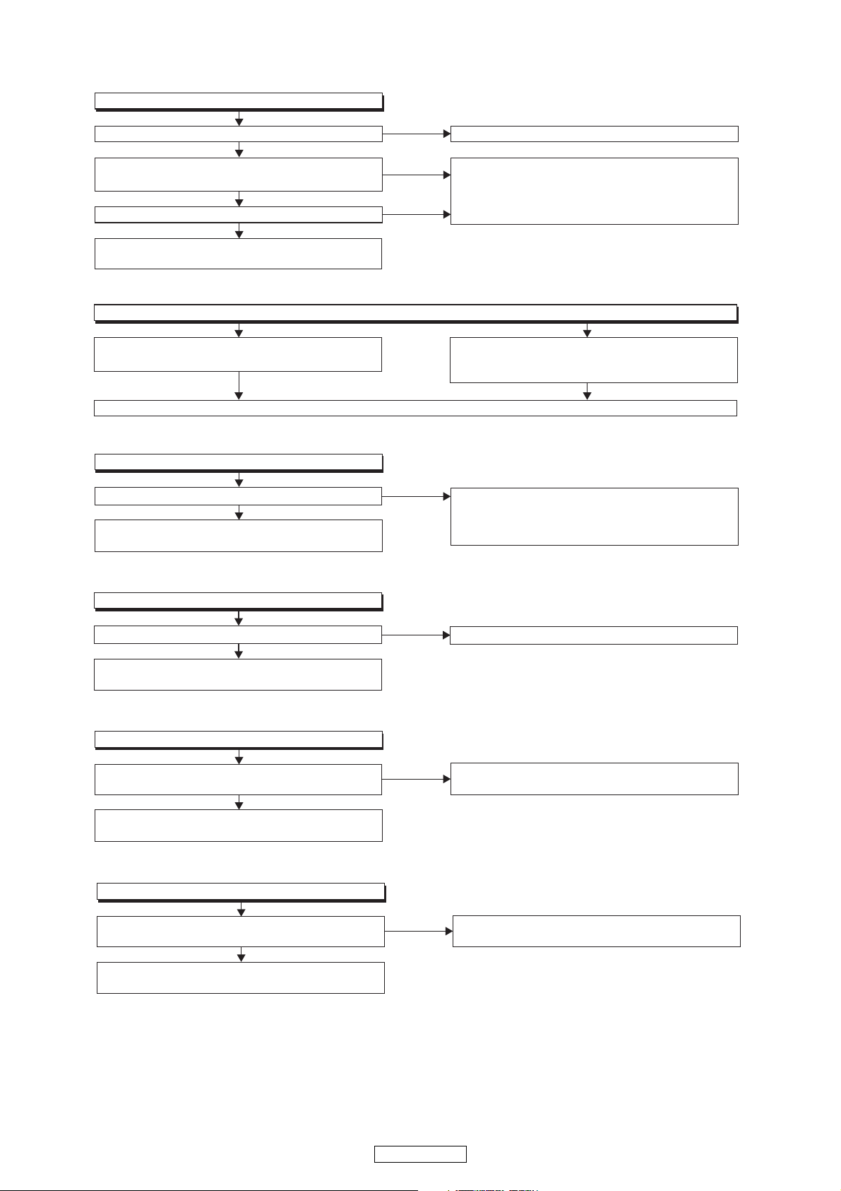
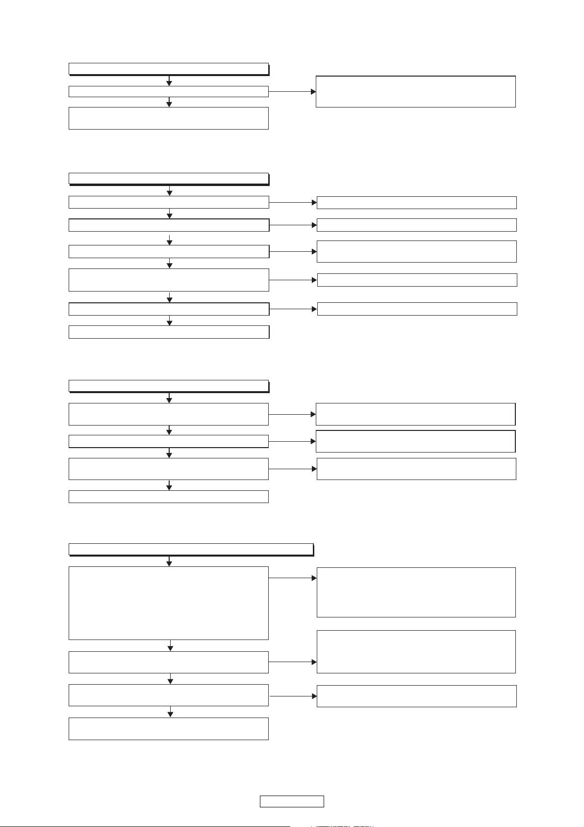
FLOW CHART NO.1 (8U-110042:POWER UNIT)
The power cannot be turned on.
Is the fuse normal?
Yes
Is normal state restored when once unplugged
power cord is plugged again after several seconds?
Yes
Is the +12V line voltage normal?
Yes
Check each rectifying circuit of the secondary circuit
and replace it if defective.
FLOW CHART NO.2 (8U-110042:POWER UNIT)
The fuse blows out.
The fuse blows out.
Check the presence that the primary component
is leaking or shorted and replace it if defective.
After servicing, replace the fuse.
FLOW CHART NO.3 (8U-110042:POWER UNIT)
+5V is not outputted.
Is the +12V line voltage normal?
Check IC906 and the parts in surrounding, and replace
it if defective.
Yes
No
No
No
No
See FLOW CHART NO.2 <The fuse blows out.>
Check if there is any leak or short-circuiting on the
primary circuit component, and replace it if defective.
(C903,C906,C907,C909,C914,C915,C918,C948,L901
,L902,T801)
Check the presence that the rectifying diode or
circuit is shorted in each rectifying circuit of
secondary side, and replace it if defective.
Check if there is any leak or short-circuiting on the
primary circuit component, and replace it if defective.
(C903,C906,C907,C909,C914,C915,C918,C948,L901
,L902,T801)
FLOW CHART NO.4 (8U-110042:POWER UNIT)
+3.3V is not outputted.
Is the +5V line voltage normal?
Yes
Check IC905 and the parts in surrounding, and replace
it if defective.
FLOW CHART NO.5 (8U-110042:POWER UNIT)
+9VA is not outputted.
Is the voltage of +9V or more supplied to
Corrector terminal of TR813?
Yes
Check TR813 and the periphery circuit, and replace it
if defective.
FLOW CHART NO.6 (8U-110042:POWER UNIT)
-9VA is not outputted.
Is the voltage of -9V or less supplied to
Corrector terminal of TR814?
Yes
Check TR814 and the periphery circuit, and replace it
if defective.
No
No
No
See FLOW CHART NO.3 <+3.3V is not outputted>
Check D811 and the periphery circuit, and replace it
if defective.
Check D810 and the periphery circuit, and replace it
if defective.
27
DN-S3700
FLOW CHART NO.7 (8U-310011:MAIN UNIT)
+12V is not outputted.
Is 3.3V voltage supplied to 7pins(PVCC) of IC403?
Yes
Check IC403 and the periphery circuit, and replace
it if defective.
FLOW CHART NO.8 (8U-110043:PANEL UNIT)
The VFD does not light up.
No
Check whether parts C426 and C427 are linked,
short-circuited or open and whether FB402 is open,
and replace any faulty parts.
Is 3.3V voltage supplied to 44pins(VDD) of FL901?
Yes
Is 40V voltage supplied to 41pins(HV2) of FL901?
Yes
Is 30V voltage supplied to 40pins(HV1) of FL901?
Yes
Are the filament voltage supplied between 1pin
and 49pin of the fluorescent display tube (FL901)?
Yes
Is voltage supplied to 34pins(RESET) of FL901?
Yes
Replace the fluorescent display tube(FL901).
FLOW CHART NO.9 (8U-110043:PANEL UNIT)
The key operation is not functioning.
Are the contact point and the installation state of the
tact switche normal?
Yes
Does LED light correctly ?
Yes
When pressing each switches, do the voltage of
each pin of IC702 increase?
Yes
Replace IC702(IC802).
No
No
No
No
No
No
No
No
Check the +3.3V line and service it if defective.
Check the HV(+40V) line and service it if defective.
Check ZD901 and the periphery circuit, and service
it if defective.
Check the F1/F2 line and service it if defective.
Check the RESET line and service it if defective.
Re-install the switches correctly or replace
the poor switch.
Check the TR701~708and their periphery, and service
it if detective.
Check the switches and their periphery, and service
it if detective.
FLOW CHART NO.10 (8U-110042:POWER UNIT)
Both functions of picture and sound do not operate normally.
The USB memory in which test signal (MP3,WAV)
No
of 1kHz/0dB is written is prepared.
With USB memory playback mode, with the test signal
of 1kHz/0dB it repeats between B from A and puts in
playback state.
Are the audio signals outputted to 11,12pin(Rch) and
17,18pin(Lch) of IC802?
Yes
Are the audio signals outputted to 7pin(Rch) and
1pin(Lch) of IC804?
Yes
Is the TR807 collector L (-9V) when muting
is canceled?
Yes
No
No
Check periphery circuit from 7pin and 1pin to
JK801 of IC804, and
replace it if defective.
DN-S3700
Check the input signal from CY112 to IC802 and their
periphery, and service it if detective.When the
input signal is correct, IC802 or IC803 is replaced.
(Note:For the IC802 OUT signal,
the right and left are inversely output internally.)
Check periphery circuit from 14pin and 15pin to
IC804 of IC802, and service it if defective.
When the periphery circuit is correct, IC804 is
replaced.
Check TR807 and the periphery circuit, and service it if
defective.
28
 Loading...