


 Loading...
Quickstart Guide
Guía de inicio rápido
Guide d’utilisation rapide
Guida rapida
Schnellstart-Anleitung
Appendix
English ( 3 – 12 )
Español ( 13 – 22 )
Français ( 23 – 32 )
Italiano ( 33 – 42 )
Deutsch ( 43 – 52 )
English ( 53 – 55 )
Quickstart Guide (English)
Introduction
DN-508MX is a professional 8-zone mixer and with remote controllability via RS-232C and IP. It has professional-grade audio circuitry, mic/line pad functions, full BTL (bridge-tied load) balanced outputs, 3-band input equalization, 5-band output equalization, priority, delay, dynamics, and an automatic power-saving function. When connected to a computer, you can use a web-based interface to control the system, as well.
Please see this guide’s Setup chapter to learn how to integrate DN-508MX with your audio system, and then refer to the Operation chapter to start using DN-508MX.
Box Contents
DN-508MX
Euroblock Connectors
(4) 5-Pin (for the Line Outputs 1–8)
(2) 4-Pin (for Mic/Line Inputs 1 & 2)
(4) 3-Pin (for Mic/Line Inputs 3–6)
(1) 2-Pin (for the Mute connector)
Power Cable
Quickstart Guide
Safety & Warranty Manual
Important: Visit denonpro.com and download the complete User Guide, which contains complete instructions on how to use the DN-508MX web interface.
Support
For the latest information about this product (system requirements, compatibility information, etc.) and product registration, visit denonpro.com.
3

Features
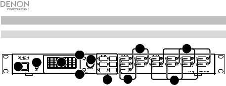
Front Panel
|
|
4 |
|
9 |
11 |
|
6 |
3 |
|
|
|
1 |
2 |
|
|
|
|
|
5 |
|
|
|
|
|
|
7 |
8 |
10 |
|
|
|
|
1.Power Button: Press this button to power DN-508MX on or off.
2.Display: This screen indicates the current settings, status, etc.
3.Volume/Sel: Turn the knob to navigate or scroll through the options shown in the display, and then press the knob to select one.
4.Menu: Press this button to switch between the Menu and the settings of the current zone in the display. In the Menu, turn the Volume/Sel knob to navigate or scroll through the available options, and then press the knob to select it.
5.Mute/Back: When viewing the settings of the current zone, press this button to select the Mute setting. To mute or unmute the zone, turn the Volume/Sel knob to select Mute or Unmute, and then press it to confirm your choice.
When in the Menu, press this button to return to the previous screen.
6.Aux In (1/8” / 3.5 mm): Use a standard stereo 1/8” (3.5 mm) cable to connect an optional audio source to this stereo input. When a cable is connected to this input, the Aux In RCA inputs on the rear panel will be disabled.
7.Mic/Line Indicators: These lights will illuminate different colors to show the signal status of each mic/line input:
•Off: The input is receiving no signal or a very low-level signal.
•Green: The input is receiving a signal at an optimal level.
•Amber: The input’s signal is very high.
•Red: The input’s signal is “peaking” (higher than 0 dB). Decrease its Gain knob on the rear panel or decrease the volume of the source to prevent “clipping” (distortion).
8.Source Indicators: These lights will illuminate different colors to show the signal status of the aux in and ST inputs:
•Off: The input is receiving no signal or a very low-level signal.
•Green: The input is receiving a signal at an optimal level.
•Amber: The input’s signal is very high.
•Red: The input’s signal is “peaking” (higher than 0 dB). Decrease the volume of the source to prevent “clipping” (distortion).
9.Source Selectors: Press one of these buttons to assign or unassign that source to the currently selected zone. When a source is assigned to the zone, its button will be lit amber. To select a zone, press one of the output selectors.
4
10.Output Indicators: These lights will illuminate different colors to show the signal status of the line outputs (zone outputs):
•Off: The output is sending no signal or a very low-level signal.
•Green: The output is sending a signal at an optimal level.
•Amber: The output’s signal is very high.
•Red: The output’s signal is “peaking” (higher than 0 dB). Decrease the volume of the zone to prevent “clipping” (distortion).
11.Output Selectors: Press one of these buttons to select that zone. The button for the currently selected zone will be lit amber.
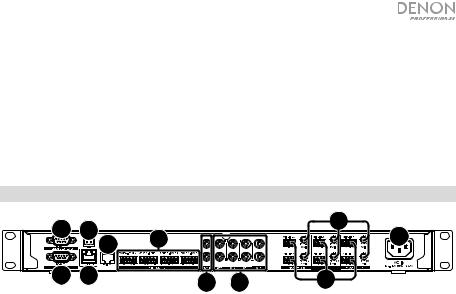
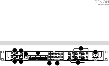
Rear Panel
9 |
7 |
|
|
|
|
4 |
10 |
2 |
|
|
1 |
||
|
|
|
|
|||
|
|
|
|
|
|
|
8 |
11 |
|
|
5 |
6 |
3 |
1.Power Input: Use the included power cable to connect this input to a power outlet.
2.Line Outputs: Use Euroblock connectors to connect your loudspeakers to these outputs. Each group of 5 connections corresponds to 2 zones. Each zone has a hot (H) and cold (C) connector, and each pair of zones shares the ground (G) connector. Make sure each loudspeaker is connected to the desired zone.
3.Mic/Line Inputs: Use Euroblock connectors to connect your mic-level or line-level audio sources to these inputs. Each input has a hot (H), cold (C), and ground (G) connector. Inputs 1 and 2 have an additional connector for Page Switch. Remember to adjust the Gain knob to set the input volume level.
4.Mic/Line Gain: Turn these knobs to set the input gain for each mic/line input.
5.Aux In (RCA): Use a standard stereo RCA cable to connect an optional audio source to this stereo input. When a cable is connected to the Aux In on the front panel, these inputs will be disabled.
6.ST Inputs: Use standard stereo RCA cables to connect line-level audio sources to these inputs.
7.Mute Connector: Use a 2-pin Euroblock connector to attach a switch to this connector. The switch can then mute or unmute the incoming signal from all audio sources.
8.Remote Port: This port lets you connect a computer to DN-508MX. Use a 9-pin D-Sub cable to make this connection. You can use the computer with a third-party utility to manage DN-508MX via serial communication.
9.Remote Extend Port: This port lets you connect another DN-508MX to the host device. Use a 9-pin D-Sub cable to make this connection. You can use a computer with a thirdparty utility to control all connected DN-508MX units via serial communication.
10.RS-422 Port: This port lets you connect a host device (usually a computer) to DN-508MX. You can then use a third-party utility to control DN-508MX via serial communication. Use a standard analog telephone cable with RJ45 connectors to make this connection.
11.Ethernet Port: This port lets you connect DN-508MX to a network. Connect this port to a computer via a network switch or router. Alternatively, connect it directly to a computer using an Ethernet crossover cable. This connection lets you control DN-508MX though the web interface.
5

Setup
Items not listed under Introduction > Box Contents are sold separately.
To set up DN-508MX with your sound system:
1.If you are using any audio source with RCA outputs (Blu-ray® players, stereos, etc.), use standard RCA cables to connect them to the ST inputs on the rear panel. Your audio sources must be line-level (no phono-level turntables).
2.If you are using an amplifier or other audio source with outputs that can be wired into standard Euroblock connectors, connect them to the mic/line inputs on the rear panel.
3.Use standard Euroblock connectors to connect the loudspeakers of your different zones to the line outputs on the rear panel. Each group of 5 connections corresponds to 2 zones. Each zone has a hot (H) and cold (C) connector, and each pair of zones shares the ground (G) connector.
4.To manage DN-508MX using its web interface, connect the Ethernet port and your computer to a network switch or router using standard Ethernet cables. If your computer is wirelessly connected to your router, connect just DN-508MX to that router. Alternatively, connect DN508MX’s Ethernet port directly to a computer using an Ethernet crossover cable.
To manage DN-508MX using serial communication, connect the remote port to your computer using a 9-pin D-Sub cable. Use a third-party utility to manage DN-508MX.
Tip: We recommend using the web interface to control DN-508MX rather than serial communication. It is much easier to use the web interface via IP communication than a thirdparty utility via RS-232 serial communication.
5.Use the included power cable to connect DN-508MX to a power outlet.
6.Power on all of your audio sources (Blu-ray players, stereos, microphones, amplifiers, etc.).
7.Power on DN-508MX.
Example:
Computer |
|
|
To Zone |
|
Speakers |
Router |
Blu-ray Player |
Zone 1 |
Zone 2 |
Zone 3 |
Zone 4 |
Zone 5 |
Amplifier
Microphones |
Power |
|
Zone 6 |
Zone 7 |
Zone 8 |
6
Operation
After setting up and powering on DN-508MX and your connected devices, you can start using DN-508MX.
Important: The default administrator password is adminpwd. There is no default operator password.
Navigating the Display and Menus
To switch between the Menu and the settings of the current zone, press Menu.
To move through the options in the display, turn the Volume/Sel knob.
To select an option in the display, press the Volume/Sel knob.
To return to the previous screen, press Mute/Back.
Managing Zones
To select a zone, press the desired output selector. The currently selected one will be lit amber. The source selectors of any audio sources that are assigned to that zone will light up amber, as well.
To assign or unassign an audio source to a zone, select it (described above), and then press the desired source selectors. The source selectors for currently assigned audio sources will be lit amber.
To set the volume level of a zone, select it (described above), and then turn the Volume/Sel knob.
Using the Web Interface
Important: To use the web interface, both DN-508MX and your computer must be connected to the same network. We recommend connecting the Ethernet port and your computer to a network switch or router using standard Ethernet cables. If your computer is wirelessly connected to your router, connect just DN-508MX to that router. Alternatively, connect DN508MX’s Ethernet port directly to a computer using an Ethernet crossover cable.
Important: Visit denonpro.com and download the complete User Guide, which contains complete instructions on how to use the DN-508MX web interface.
To open the DN-508MX web interface, on your computer, open a web browser.
•If DN-508MX is connected directly to a computer, go to http://192.168.0.1 in your web browser. You may have to enter the operator password. There is no default password, but if you have already set one, you will have enter it here.
•If DN-508MX is connected to a network switch or router (wirelessly or wired), use the Menu button and the Volume/Sel knob to do the following:
i.Press Menu to enter the Menu.
ii.Select and enter 2. System, then Ethernet, then IP Address, and then the Auto setting (you may have to enter the administrator password).
iii.Set Auto to On, and select Yes when asked if you want to apply the change.
iv.When the display shows the IP Address screen again, it will display a 12-digit IP address. Enter this address into your web browser as http://###.###.###.###. You may have to enter the operator password. There is no default password, but if you have already set one, you will have enter it here.
7
To use the controls show in the web interface:
•Pages: Click the Output, Input, or Settings button at the top of the window to view each page in the web interface below.
•Faders: Click and drag a fader to set its level. Alternatively, click the dB field below it, enter a value with your computer keyboard, and then click elsewhere in the page.
•Menus: Click a menu, and then click an option to select it.
•Buttons: Click a button to select it.
•Checkbox: Click a checkbox to select or deselect it.
•Text Field: Click a text field, enter a name with your computer keyboard, and then click elsewhere on the page.
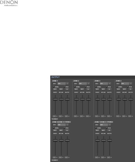
Output
Click the Output button at the top to view the Output page where you can set the levels, equalization, inputs, and mute status of each zone.
If a zone is stereo, it will actually use 2 zones (e.g., Zones 1–2, Zones 3–4), which will share the same output settings. If a zone is mono, it will use one zone only.
Input Menu: Click this menu to select which source is sent to the zone.
Signal: This light indicates that the zone is sending out an audio signal.
Peak: This light indicates that the zone is sending out an audio signal that is “peaking” (exceeding 0 dB). If this happens, lower the level of the Source or Mic/Line fader.
Mute: Click this button to mute or unmute the source. The button will be highlighted when muted.
Input: Click this button to open the Zone Input window. In this window, click and drag each fader to set the audio signal level that each mic/line input sends specifically to that zone. (This does not affect the levels that those inputs send to other zones.)
EQ: Click this button to open the Zone EQ window. In this window, click each menu to set the frequency (Freq), Gain, or bandwidth (Q) of the 5 frequency ranges: Low, Mid-Low, Mid, Mid-High, and High.
Source: Click and drag this fader to set the input level of the source you selected in the Input Menu (described above).
Mic/Line: Click and drag this fader to set the overall level of the mic/line inputs. This setting is applied in addition to the settings in the Zone Input window (described above).
Master: Click and drag this fader to set the zone’s overall output level.
To Zone5-8 / To Zone1-4: Click either of these buttons to jump to the lower or upper half of the page, respectively.
8
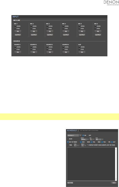
Input
Click the Input button at the top to view the Input page where you can set the equalization or output level of each input (the mic/line inputs, ST inputs, or Aux In).
Signal: This light indicates that the input is receiving an audio signal.
Peak: This light indicates that the input is receiving an audio signal that is “peaking” (exceeding 0 dB). If this happens, reduce the setting of the Mic/Line Gain knob on the rear panel (for Mic 1–6) or on the audio source itself (for Source 1–4 and Aux).
EQ: Click this button to open the Input EQ window. In this window, click each menu to set the frequency (Freq), Gain, or bandwidth (Q) of the 3 available equalizations: a low-shelving filter (SHL), a high-shelving filter (SHH), and a parametric equalizer (PEQ). Only the parametric equalizer has a bandwidth control.
Output: Click this button to open the Mic Output window. In this window, click and drag each fader to set the audio signal level that each mic/line channel sends specifically to each zone.
Settings
Click the Settings button at the top and select Schedule, I/O Name, or System to view the corresponding settings page.
Important: Click the lock icon at the top of the page to lock or unlock the settings. When locked, you cannot edit any of the settings. This is helpful to prevent any accidental changes to the overall operation.
Schedule
Schedule: Click this menu to select a schedule to view.
•On/Off: Click one of these buttons to enable or disable the schedule. You can use multiple schedules simultaneously.
•Date: Click this menu to set a specific date on which to apply the schedule (instead of regular days of the week). Click each menu to select the Month, Day, and Year. The ** option sets the schedule to repeat every month, day, or year.
•Day of Week: Click this menu to apply the schedule regularly to certain days of the week (instead of a specific date). Click each checkbox to select or deselect the day.
•Time: Click each menu (Hour and Minute) to set when the schedule will be applied. The ** option sets the schedule to repeat every hour.
•Restore: Click this menu to reset all changes you have made to the current schedule.
•Save: Click this menu to save the currently shown schedule.
9
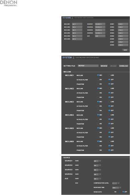
I/O Name
This window shows the names of all of your inputs (mic/line inputs, ST inputs, and Aux In) and zone (line outputs). Click each field and enter a name using your computer keyboard. Click Save to save the names.
System
•Setting File: This field shows the currently loaded setting file, if any. To download the current setting file (if any) to your computer, click Download. To upload a setting file from your computer to DN-508MX, click Browse, find and select the file, and then click Upload.
•Mic/Line: For each mic/line input, select whether the input is a microphone (Mic) or a line-level device (Line), whether the high-pass filter should be enabled (On) or disabled (Off), and whether the microphone should receive phantom power (On) or not (Off). Please note that most dynamic microphones do not require phantom power, while most condenser microphones do. Consult your microphone’s documentation to find out whether it needs phantom power.
•Source: Click each Gain menu to set the gain trim level of each audio source. All sources have an editable automatic gain control (AGC), which adjusts the gain level to help reduce noise in the signal:
oCompensation Level: Click this menu to set how much gain is applied after the signal is compressed by the AGC.
oResponse Time: Click this menu to set how quickly the AGC reacts to audio signal.
oNoise Gate: Click one of the buttons to enable (On) or disable (Off) the noise gate. When on, the audio signal will be automatically muted if it is below a certain volume level. This eliminates moments during which the source is not producing any sound but there is still detectable noise in the audio signal.
10
•Output: Use these settings to determine how each zone manages its audio output.
oZone Mono/Stereo: Click this menu to set whether the audio signal the zone plays is monaural (Mono) or binaural (Stereo). When set to Stereo it will actually use 2 zones (e.g., Zones 1–2, Zones 3–4), which will share the same output settings.
oPriority Settings: Each zone has settings for 1st priority and 2nd priority. When the mic/line input (set in the Source menu) detects an incoming audio signal, any other signal sent to that zone will be attenuated (“ducked”) so the incoming signal can be heard. The 1st-priority source will attenuate the 2nd-priority source.
Volume: Click this menu to set the volume level of the incoming audio signal.
Source: Click this menu to set the source for the priority: Mic/Line 1–6 or no source (None). Setting both priorities to the same mic/line input will result in greater-than-normal attenuation.
Threshold: Click this menu to set the threshold. The incoming audio signal must be louder than this threshold to attenuate the current signal. A lower threshold produces more attenuation.
Attack Time: Click this menu to set how long it takes for the current signal to be fully attenuated.
Hold Time: Click this menu to set how long the current signal remains fully attenuated after the incoming audio falls below the threshold.
Release: Click this menu to set how long it takes from the fully attenuated signal to return to its previous level after the incoming audio signal falls below the threshold.
Attenuation Level: Click this menu to set how much the current signal’s volume is attenuated (“ducked”).
oDelay: Click this menu to set how long it takes for the zone to play any incoming audio signal after it receives it. This is useful when multiple zones are playing the same audio signal— listeners in certain areas may hear that same signal multiple times because the sound from each zone reaches them at different times rather than all at once. Delaying the zone’s audio output can help prevent this effect.
oDynamics: These settings determine the dynamic control (via compression) of the zone’s output signal.
On/Off: Click this menu to enable (On) or disable (Off) the zone’s dynamic control.
Threshold: Click this menu to set the threshold. The incoming audio signal must be louder than this threshold to trigger the dynamic control.
Ratio: Click this menu to set the ratio of the dynamic control—how much the signal is attenuated relative to its original level.
Attack Time: Click this menu to set how long it takes for the dynamic control to compress the signal.
Release: Click this menu to set how long it takes from the compressed signal to return to its original level after the incoming audio signal falls below the threshold.
Gain: Click this menu to set how much gain is applied after the signal is compressed.
Knee: Click this menu to set the knee of the dynamic control. This determines how sharp or smooth the “curve” is when compression is applied at the threshold. A “hard” knee produces very dramatic compression, while a “soft” knee produces a more naturalsounding compression.
11
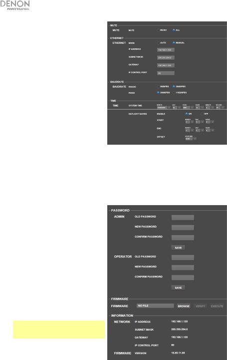
•Mute: Click one of these buttons to mute either the music only (Music) or all audio signals (All).
•Ethernet: Use these controls to configure your Ethernet settings. Click one of the Mode buttons to set them to detect the network settings automatically (Auto) or to use the settings you enter yourself (Manual). Click the IP Address, Subnet Mask, Gateway, or IP Control Port fields and enter the numbers for each using your computer keyboard.
•Baudrate: Click one of the buttons for each port to set the baud rate of each one. RS232C is for the remote port. RS422 is for the RS-422 port. Each rate is shown bits per second (BPS).
•Time: Click each menu next to System Time to set the current month, day, year, hour, minute, and second. DN-508MX will display this at the top of the web interface and will use it for scheduling.
Click one of the Enable buttons to enable (On) or disable (Off) daylight saving time. When on, click each menu below it to set the month, day, and hour that daylight saving will start and end. Click the Offset menu to select how much the time will be shifted.
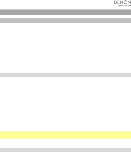
•Password: Use these fields to set a new password for the administrator (Admin), which can control all DN508MX functions, or the operator (Operator), which can control only certain functions. Click each field and enter the characters for your current password (Old Password) and the new password twice (New Password and
Confirm Password). Click Save to save the new password.
•Firmware: This field shows the DN508MX firmware file to upload, if any. To upload a firmware file from your computer to DN-508MX, click Browse, and then find and select the file. After that, click Verify to confirm the file is valid. If it is valid, then click Execute to update the firmware.
Important: Visit denonpro.com to download the latest firmware for DN508MX.
•Information: This section shows the current network addresses (as set in the Ethernet section) and firmware version (as set in the Firmware section).
12
Guía de inicio rápido (Español)
Introducción
El DN-508MX es un mezclador profesional de 8 zonas controlable remotamente a través de RS-232C e IP. Cuenta con circuitos de audio de grado profesional, funciones de pad de micrófono/línea, salidas balanceadas de BTL (carga puenteada) completas, ecualización de entrada de 3 bandas, ecualización de salida de 5 bandas, prioridad, retraso (delay), dinámica y una función de ahorro de energía automática. Una vez conectado a un ordenador, también puede utilizar una interfaz basada en la web para controlar el sistema.
Consulte el capítulo Instalación para información acerca de cómo integrar el DN-508MX con su sistema de audio y luego consulte el capítulo Funcionamiento para comenzar a utilizar el DN-508MX.
Contenido de la caja
DN-508MX
Conectores Euroblock
(4) 5 patillas (para las salidas de línea 1–8)
(2) 4 patillas (para las entradas de micrófono/línea 1 y 2)
(4) 3 patillas (para las entradas de micrófono/línea 3–6)
(1) 2 patillas (para el conector de silenciamiento)
Cable de corriente
Guía de inicio rápido
Manual sobre la seguridad y garantía
Importante: Visite denonpro.com y descargue la Guía del usuario completa, la cual contiene instrucciones detalladas sobre cómo utilizar la interfaz web del DN-508MX.
Soporte
Para obtener la información más reciente acerca de este producto (requisitos de sistema, información de compatibilidad, etc.) y registrarlo, visite denonpro.com.
13
Características
Panel frontal
|
|
4 |
|
9 |
11 |
|
6 |
3 |
|
|
|
1 |
2 |
|
|
|
|
|
5 |
|
|
|
|
|
|
7 |
8 |
10 |
|
|
|
|
1.Botón de encendido: Pulse este botón para encender o apagar el DN-508MX.
2.Pantalla: Esta pantalla indica los ajustes, el estado, etc. actuales.
3.Volumen/Selección: Gire la perilla para navegar o desplazarse por las opciones que se muestran en la pantalla y luego pulse la perilla para seleccionar una de ellas.
4.Menú: Pulse este botón para alternar entre el menú y los ajustes de la zona actual en la pantalla. En el menú, gire la perilla Volume/Sel para navegar o desplazarse a través de las opciones disponibles y luego pulse la perilla para seleccionar una de ellas.
5.Silenciar/Atrás: Al visualizar los ajustes de la zona actual, pulse este botón para seleccionar los ajustes del silenciamiento. Para silenciar o anular el silenciamiento de la zona, gire la perilla Volume/Sel para seleccionar “Mute” (silenciar) o “Unmute” (anular el silenciamiento) y luego pulse la para confirmar su selección.
Desde el menú, pulse este botón para volver a la pantalla anterior.
6.Entrada auxiliar (1/8 pulg. / 3,5 mm): Utilice un cable estéreo estándar de 3,5 mm (1/8 pulg.) para conectar una fuente de audio opcional a esta entrada estéreo. Cuando se conecta un cable a esta entrada, las entradas auxiliares RCA del panel trasero quedarán desactivadas.
7.Indicadores de micrófono/línea Estas luces se encenderán con diferentes colores para mostrar el estado de la señal de cada entrada de micrófono/línea:
•Apagadas: La entrada no está recibiendo ninguna señal o una señal de muy bajo nivel.
•Verde: La entrada está recibiendo una señal con un nivel óptimo.
•Ámbar: La señal de la entrada es demasiado alta.
•Rojo: La señal de la entrada está llegando a su pico (más de 0 dB). Disminuya la perilla Gain (ganancia) del panel trasero o disminuya el volumen de la fuente para evitar el “recorte” (distorsión).
8.Indicadores de fuente: Estas luces se encenderán con diferentes colores para mostrar el estado de la señal de las entradas auxiliares y ST:
•Apagadas: La entrada no está recibiendo ninguna señal o una señal de muy bajo nivel.
•Verde: La entrada está recibiendo una señal con un nivel óptimo.
•Ámbar: La señal de la entrada es demasiado alta.
•Rojo: La señal de la entrada está llegando a su pico (más de 0 dB). Disminuya el volumen de la fuente para evitar el “recorte” (distorsión).
9.Selectores de fuente: Pulse uno de estos botones para asignar o desasignar esa fuente a la zona actualmente seleccionada. Cuando una fuente es asignada a la zona, su botón se encenderá en ámbar. Para seleccionar una zona, pulse uno de los selectores de salida.
14
10.Indicadores de salida: Estas luces se encenderán con diferentes colores para mostrar el estado de la señal de las salidas de línea (salidas de zona):
•Apagadas: La entrada no está recibiendo ninguna señal o una señal de muy bajo nivel.
•Verde: La salida está enviando una señal con el nivel óptimo.
•Ámbar: La señal de la salida es demasiado alta.
•Rojo: La señal de la salida está llegando a su pico (más de 0 dB). Disminuya el volumen de la zona para evitar el “recorte” (distorsión).
11.Selectores de salida: Pulse uno de los botones para seleccionar esa zona. El botón de la zona actualmente en reproducción se encenderá en ámbar.
Panel trasero
9 |
7 |
|
|
|
|
4 |
10 |
2 |
|
|
1 |
||
|
|
|
|
|||
|
|
|
|
|
|
|
8 |
11 |
|
|
5 |
6 |
3 |
1.Entrada de corriente: Utilice el cable de corriente incluido para conectar esta entrada a una toma de corriente.
2.Salidas de línea: Utilice conectores Euroblock para conectar sus altavoces a estas salidas. Cada grupo de 5 conexiones corresponde a 2 zonas. Cada zona tiene un conector caliente (H) y un conector frío (C), y cada par de zonas comparte el conector a tierra (G). Asegúrese de que cada altavoz esté conectado a la zona deseada.
3.Entradas de micrófono/línea: Utilice conectores Euroblock para conectar sus fuentes de audio de nivel de micrófono o de nivel de línea a estas entradas. Cada entrada tiene un conector caliente (H), un conector frío (C), y un conector a tierra (G). Las entradas 1 y 2 tienen un conector adicional para el interruptor de página. Recuerde ajustar la perilla Gain para definir el nivel del volumen de entrada.
4.Ganancia de micrófono/línea: Gire esta perilla para ajustar la ganancia de entrada para cada entrada de micrófono/línea.
5.Entrada auxiliar (RCA): Utilice un cable RCA estéreo estándar para conectar una fuente de sonido a esta entrada. Cuando se conecta un cable a la entrada auxiliar del panel frontal, estas entradas quedarán desactivadas.
6.Entradas ST: Utilice cables RCA estéreo estándar para conectar fuentes de audio de nivel de línea a estas entradas.
7.Conector de silenciamiento: Utilice un conector Euroblock de 2 patillas para conectar un interruptor a este conector. El interruptor entonces podrá silenciar o anular el silenciamiento de la señal entrante desde todas las fuentes de audio.
8.Puerto remoto: Este puerto le permite conectar un ordenador al DN-508MX. Utilice un cable D- Sub de 9 patillas para realizar esta conexión. Podrá entonces utilizar el ordenador con un programa de terceros para manejar el DN-508MX a través de comunicación en serie.
9.Puerto de extensión remota: Este puerto le permite conectar otro DN-508MX al dispositivo anfitrión. Utilice un cable D-Sub de 9 patillas para realizar esta conexión. Podrá entonces utilizar un ordenador con un programa de terceros para controlar todos los DN-508MX conectados a través de comunicación en serie.
10.Puerto RS-422: Este puerto le permite conectar un dispositivo anfitrión (usualmente un ordenador) al DN-508MX. Podrá entonces utilizar un programa de terceros para controlar el DN508MX a través de comunicación en serie. Utilice un cable analógico de teléfono estándar con conectores RJ45 para realizar esta conexión.
11.Puerto Ethernet: Este puerto le permite conectar el DN-508MX a una red. Conecte este puerto a un ordenador a través de un conmutador o enrutador de redes. Como alternativa, conéctelo directamente a un ordenador mediante un cable Ethernet cruzado. Esta conexión le permite controlar el DN-508MX a través de la interfaz web.
15

Instalación
Los elementos que no se enumeran en Introducción > Contenido de la caja se venden por separado.
Cómo instalar DN-508MX con su sistema de sonido:
1.Si está utilizando una fuente de audio con salidas RCA (reproductores de Blu-ray®, estéreos, etc.), utilice cables RCA estándar para conectarlos a las entradas ST del panel trasero. Sus fuentes de audio deben ser de nivel de línea (no giradiscos de nivel fonográfico).
2.Si está utilizando un amplificador u otra fuente de audio con salidas que pueden cablearse a los conectores Euroblock estándar, conéctelas a las entradas de micrófono/línea del panel trasero.
3.Utilice conectores Euroblock estándar para conectar los altavoces de sus diferentes zonas a las salidas de línea del panel trasero. Cada grupo de 5 conexiones corresponde a 2 zonas. Cada zona tiene un conector caliente (H) y un conector frío (C), y cada par de zonas comparte el conector a tierra (G).
4.Para administrar el DN-508MX a través de su interfaz web, conecte el puerto Ethernet y su ordenador a un conmutador o enrutador de red utilizando cables Ethernet estándar. Si su ordenador se conecta a su enrutador de forma inalámbrica, conecte solamente el DN-508MX a ese enrutador. Como alternativa, conecte el puerto Ethernet del DN-508MX directamente a un ordenador mediante un cable Ethernet cruzado.
Para administrar el DN-508MX a través de la comunicación en serie, conecte el puerto remoto de su ordenador utilizando un cable D-Sub de 9 patillas. Utilice un programa de terceros para administrar el DN-508MX.
Consejo: Recomendamos utilizar la interfaz web para controlar el DN-508MX en lugar de la comunicación en serie. Es mucho más fácil utilizar la interfaz web a través de la comunicación IP que una herramienta de terceros a través de la comunicación RS-232 en serie.
5.Utilice el cable de corriente incluido para conectar el NDN-508M a una toma de corriente.
6.Encienda todas sus fuentes de audio (reproductores de Blu-ray, estéreos, micrófonos, amplificadores, etc.).
7.Encienda el DN-508MX.
Ejemplo:
Ordenador |
|
|
|
A las |
|
|
amplificadore |
Amplificador |
|
s de zona |
|
|
|
|
Enrutador |
Reproductor Blu-ray |
Micrófonos Suministro eléctrico |
Zona 1 |
Zona 2 |
Zona 3 |
Zona 4 |
Zona 5 |
Zona 6 |
Zona 7 |
Zona 8 |
16
Funcionamiento
Después de configurar y encender el DN-508MX y sus dispositivos conectados, puede comenzar a utilizar el DN-508MX.
Importante: La contraseña predeterminada del administrador es adminpwd. No existe una contraseña predeterminada para el operador.
Navegación por la pantalla y los menús
Para alternar entre el menú y los ajustes de la zona actual, pulse Menu.
Para desplazarse a través de las opciones en la pantalla, gire la perilla Volume/Sel.
Para seleccionar una opción en la pantalla, pulse la perilla Volume/Sel.
Para volver a la pantalla inicial, pulse Mute/Back.
Administración de las zonas
Para seleccionar una zona, pulse el selector de salida deseado. El selector actualmente seleccionado se encenderá en ámbar. Los selectores de fuente de toda fuente de audio que esté asignada a esa zona también se encenderán en ámbar.
Para asignar o desasignar una fuente de audio a una zona, selecciónela (como se describe anteriormente) y luego pulse los selectores de fuente deseados. Los selectores de fuente para las fuentes de audio actualmente asignadas se encenderán en ámbar.
Para ajustar el nivel de volumen de una zona, selecciónela (como se describe anteriormente) y luego gire la perilla Volume/Sel.
Uso de la interfaz web
Importante: Para utilizar la interfaz web, tanto el DN-508MX como su ordenador deben estar conectados a la misma red. Recomendamos conectar el puerto Ethernet y su ordenador a un conmutador o enrutador de red utilizando cables Ethernet estándar. Si su ordenador se conecta a su enrutador de forma inalámbrica, conecte solamente el DN-508MX a ese enrutador. Como alternativa, conecte el puerto Ethernet del DN-508MX directamente a un ordenador mediante un cable Ethernet cruzado.
Importante: Visite denonpro.com y descargue la Guía del usuario completa, la cual contiene instrucciones detalladas sobre cómo utilizar la interfaz web del DN-508MX.
Para abrir la interfaz web del DN-508MX en su ordenador, abra un navegador web.
•Si el DN-508MX se conecta directamente a un ordenador, vaya a http://192.168.0.1 en su navegador web. Puede que tenga que introducir la contraseña del operador. No existe una contraseña predeterminada, pero si ya ha definido una, tendrá que introducirla aquí.
•Si el DN-508MX está conectado a un conmutador o enrutador de red (inalámbrico o mediante cables), utilice el botón Menu y la perilla Volume/Sel para realizar lo siguiente:
i.Pulse Menu para entrar al menú.
ii.Seleccione e introduzca 2. System (Sistema), luego Ethernet, luego IP Address (Dirección IP), y luego el ajuste Auto (puede que tenga que introducir la contraseña de administrador).
iii.Ajuste Auto a On (Activado) y seleccione Yes (Sí) cuando se le pregunte si desea aplicar el cambio.
iv.Cuando la pantalla muestre nuevamente la dirección IP, mostrará una dirección IP de 12 dígitos. Introduzca esta dirección en su navegador web de esta forma http://###.###.###.###. Puede que tenga que introducir la contraseña del operador. No existe una contraseña predeterminada, pero si ya ha definido una, tendrá que introducirla aquí.
17
Loading...