


User Guide |
|
English (3–6) |
Guía del usuario |
|
Español (7–10) |
Guide d’utilisation |
|
Français (11–14) |
Guida per l’uso |
|
Italiano (15–18) |
Benutzerhandbuch |
|
Deutsch (19–22) |
Appendix |
|
English (23) |

2

User Guide (English)
Introduction
Thank you for purchasing the DN-470A. At Denon Professional, performance and reliability mean as much to us as they do to you. That’s why we design our equipment with only one thing in mind—to make your performance the best it can be.
Box Contents
DN-470A
(2) 6-Pin Euroblock Connectors
(4) 4-Pin Euroblock Connectors
Power Cable
Rack Ears with Screws
User Guide
Safety & Warranty Manual
Support
For the latest information about this product (documentation, technical specifications, system requirements, compatibility information, etc.) and product registration, visit denonpro.com.
For additional product support, visit denonpro.com/support.
3
Features
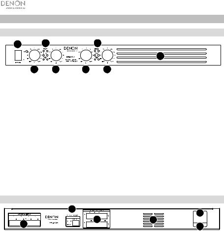
Front Panel |
|
|
|
1 |
3 |
|
3 |
|
|
|
4 |
2 |
2 |
2 |
2 |
1.Power Switch: Press this switch to power DN-470A on or off.
2.Level Knobs: Turn these knobs to set the output level for each channel.
3.Signal/Clip/Protection LEDs: These lights will illuminate different colors to show the signal status of each channel input:
•Signal LED: The input’s Signal LED will be lit green when it is receiving a signal at an optimal level.
•Clip LED: The input’s Clip LED is “peaking” when the LED is lit red (higher than 0 dB). Turn its Level knob counter-clockwise or reduce the volume of the source to prevent “clipping” (distortion).
•Protection LED: If the Protection LED turns red, the unit is in heat protection mode and will not output sound. To restore sound output, reduce the temperature by making sure there is good ventilation and by decreasing the signal level.
4.Air Intake Vents: Keep the vents clear from obstructions to allow air to flow through the front grill for proper performance.
Rear Panel
|
5 |
|
1 |
|
|
4 |
|
|
PRESET |
6 |
|
3 |
|
|
2 |
|
|
|
1.Power Inlet: Use the included power cable to connect this input to a power outlet.
2.Fuse: If the unit’s fuse is broken, lift this tab to replace the fuse. Replace it with a fuse with an appropriate rating. Using a fuse with an incorrect rating can damage the unit and/or fuse.
3.Inputs: Use Euroblock connectors to connect these channel inputs to your audio sources. Each channel has a ground (G), cold/negative (–), and hot/positive (+) connector. Make sure the wiring of each device matches each connection.
4.Outputs: Use Euroblock connectors to connect these channel outputs to your loudspeakers. Each channel has a switch for 70V and 100V. Make sure the wiring of each loudspeaker is done properly for each output.
5.Operation Mode Switch: Select the operation mode (70V or 100V) for each channel’s output by moving the dip-switches to the desired position.
6.Exhaust Vents: Air from the front intake flows through the unit and exits here. For proper performance, do not block the air vent.
4

Setup
Items not listed under Introduction > Box Contents are sold separately.
1.Use the included Euroblock connectors to connect the inputs on the rear panel to your audio sources.
•Each channel input has a ground (G), cold/negative (–), and hot/positive (+) connector.
2.Use the included Euroblock connectors to connect the outputs on the rear panel to your loudspeakers.
•Each channel output has a switch for 70V and 100V.
3.Use the included power cable to connect the power inlet to a power outlet.
4.Power on all of your audio sources (Blu-ray® players, stereos, microphones, amplifiers, etc.).
5.Press the power switch to power on DN-470A.
6.Adjust the level knobs for each channel input as necessary.
Example
Loudspeakers
Receiver
IN-Command
|
|
|
|
|
|
|
|
|
|
|
|
|
|
|
|
|
|
|
|
|
|
|
|
|
|
|
|
|
|
|
|
|
|
|
|
|
|
|
|
|
|
|
|
|
|
|
|
|
|
|
|
|
|
|
|
|
|
|
|
|
|
|
|
|
|
|
|
|
|
|
|
|
|
|
|
|
|
|
|
|
|
|
|
|
|
|
|
|
|
|
|
|
|
|
|
|
|
|
|
|
|
|
|
|
|
|
|
|
|
|
|
|
|
|
|
|
|
|
|
|
|
|
|
|
|
|
|
|
|
|
|
|
|
|
|
|
|
|
|
|
|
|
|
|
|
|
|
|
|
|
|
|
|
|
|
|
|
|
|
|
|
|
|
|
|
|
|
|
|
|
|
|
|
|
|
|
|
|
|
|
|
|
|
|
|
|
|
|
|
|
|
|
|
|
|
|
|
|
|
|
|
|
|
|
|
|
|
|
|
|
|
|
|
|
|
|
|
|
|
|
|
|
|
|
|
|
|
|
|
|
|
|
|
|
|
|
|
|
|
|
|
|
|
|
|
|
|
|
|
|
|
|
|
|
|
|
Blu-ray Player |
|
|
Loudspeakers |
|
|
|
|
|
|
|
|
|
|
|||||||||||||||||||||||||||||
|
|
|
|
|
|
|
|
|
|
|
|
|
|
|
|
|
|
|
|
|
|
|
|
|
|
|
|
|
|
|
|
|
|
|
|
|
|
|
|
|
|
|
|
|
|
|
|
|
|
|
|
|
|
|
|
|
|
|
|
|
|
|
|
|
|
|
|
|
|
|
|
|
|
|
|
|
|
|
|
|
|
|
|
|
|
|
|
|
|
|
|
|
|
|
|
|
|
|
|
|
|
|
|
|
|
|
|
|
|
|
|
|
|
|
|
|
|
|
|
|
|
|
|
|
|
|
|
|
|
|
|
|
|
|
|
|
|
|
|
|
|
|
|
|
|
|
|
|
|
|
|
|
|
|
|
|
|
|
|
|
|
|
|
|
|
|
|
|
|
|
|
|
|
|
|
|
|
|
|
|
|
|
|
|
|
|
|
|
|
|
|
|
|
|
|
|
|
|
|
|
|
|
|
|
|
|
|
|
|
|
|
|
|
|
|
|
|
|
|
|
|
|
|
|
|
|
|
|
|
|
|
|
|
|
|
|
|
|
|
Power
5
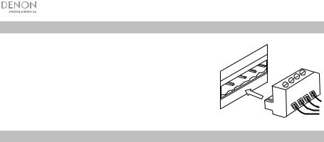
Using a Euroblock Connector
1.Twist the speaker wire to form a tight strand and insert this into the appropriate port, pushing the wire until it is secured inside.
2.Attach the Euroblock connector to the terminal on DN-470A.
3.To disconnect a wire, use a small screwdriver to press in the spring above the insert port while pulling out the wire.
Troubleshooting
If you encounter a problem, try doing these things first:
D
CH
C
CH
B
CH
A
CH
•Make sure all cables and other connected devices are properly and securely connected.
•Make sure you are using DN-470A as described in this user guide.
•Make sure your other devices or media are working properly.
•If you believe DN-470A is not working properly, check the following table for your problem and solution.
Problem: |
Solution: |
Please see: |
|
|
|
Power does not turn on. |
Make sure DN-470A’s power inlet is |
Setup |
|
properly connected to a power outlet |
|
|
using the included power cable. |
|
|
|
|
DN-470A does not |
Make sure all cable and device |
Setup |
produce any sound, or |
connections are secure and correct. |
|
the sound is distorted. |
Make sure none of the cables are |
|
|
|
|
|
damaged. |
|
|
Make sure the settings on your |
|
|
loudspeaker, mixer, etc. are correct. |
|
|
|
|
The sound has a hum or |
Check the polarity of the input |
Setup |
noise. |
connections. |
|
|
If an unbalanced connection is used, |
|
|
ensure terminal (-) is linked to GND. |
|
|
If the clip LED is lit, reduce the output |
|
|
volume. |
|
|
Check the polarity of the speaker |
|
|
connections. |
|
|
|
|
6
Guía del usuario (Español)
Introducción
Gracias por comprar el DN-470A. En Denon Professional, el rendimiento y la confiabilidad significan tanto para nosotros como para usted. Por eso es que diseñamos nuestros equipos con una sola cosa en mente—hacer que pueda tocar su mejor interpretación.
Contenido de la caja
DN-470A
(2) 6-patillas conectores Euroblock
(4) 4-patillas conectores Euroblock
Cable de corriente
"Orejas" con tornillos para racks
Guía del usuario
Manual sobre la seguridad y garantía
Soporte
Para obtener la información más reciente acerca de este producto (documentación, especificaciones técnicas, requisitos de sistema, información de compatibilidad, etc.) y registrarlo, visite denonpro.com.
Para obtener soporte adicional del producto, visite denonpro.com/support.
7
Características
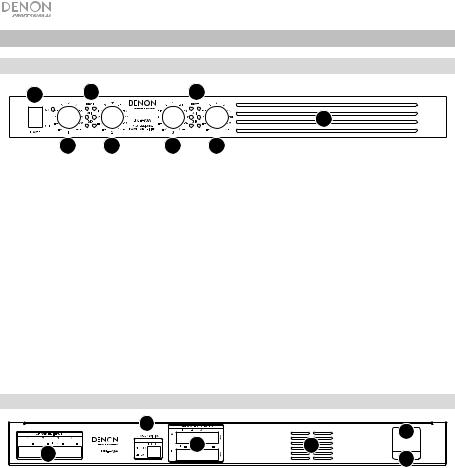
Panel frontal
1 |
3 |
|
3 |
|
|
|
4 |
2 |
2 |
2 |
2 |
1.Interruptor de encendido: Pulse este interruptor para encender o apagar el DN-470A.
2.Perilla de nivel: Gire estas perillas para ajustar el nivel de salida de cada canal.
3.LED de señal/clip: Estas luces se encenderán con diferentes colores para mostrar el estado de la señal de cada entrada de canal:
•LED de señal: El LED de señal de la entrada se encenderá de verde cuando esté recibiendo una señal con el nivel óptimo.
•LED de recorte: El LED de recorte llega a su "pico" cuando el LED se enciende de rojo (más de 0 dB). Gire su perilla Level (Nivel) en sentido antihorario o disminuya el volumen de la fuente para evitar el "recorte" (distorsión).
•LED de protección: Si el LED de protección se enciende de rojo, la unidad se encuentra en modo de protección y no emitirá sonido. Para restaurar la salida de sonido, reduzca la temperatura asegurándose de que haya una buena ventilación y disminuyendo el nivel de la señal.
4.Ventilaciones de entrada de aire: Mantenga las ventilaciones libres de obstrucciones para permitir que el aire fluya a través de la rejilla delantera asegurando así un buen funcionamiento.
Panel trasero
|
5 |
|
1 |
|
|
4 |
|
|
PRESET |
6 |
|
3 |
|
|
2 |
|
|
|
1.Entrada de corriente: Utilice el cable de corriente incluido para conectar esta entrada a una toma de corriente.
2.Fusible: Si el fusible de la unidad está roto, levante esta lengüeta para reemplazar el fusible. Reemplácelo por un fusible con especificación apropiada. Si utiliza un fusible de especificación incorrecta, puede dañarse la unidad y/o el fusible.
3.Entradas: Utilice conectores Euroblock para conectar estas entradas de canal a sus fuentes de audio. Cada entrada tiene un conector a tierra (G), un conector frío/negativo (–), y un conector caliente/positivo (+). Asegúrese de que el cableado de cada dispositivo coincida con cada conexión.
4.Salidas: Utilice conectores Euroblock para conectar estas salidas de canal a sus altavoces. Cada canal tiene un interruptor del 70 V y 100 V. Asegúrese de que el cableado de cada altavoz sea el correcto para cada salida.
5.Interruptor de modo de operación: Seleccione el modo de operación (70 o 100 V) para cada una de las salidas del canal moviendo los interruptores dip a la posición deseada.
6.Ventilaciones de escape: El aire que proviene desde las entradas delanteras fluye por la unidad y sale por aquí. Para obtener un mejor funcionamiento, no obstruya esta salida de aire.
8
 Loading...