


DP-200USB
Table of contents
 Loading...
e
SERVICE MANUAL
MODEL JP E3 E2 EK K2A E1C E1K EUT
Ver. 1
DP-200USB
FULL AUTOMATIC TURNTABLE SYSTEM
P P
For purposes of improvement, specications and design are subject to change without notice.
●
Please use this service manual with referring to the operating instructions without fail.
●
Some illustrations using in this service manual are slightly different from the actual set.
●
e
Denon Brand Company, D&M Holdings Inc.
X0392 V.01 DE/CDM 0811

SAFETY PRECAUTIONS
The following check should be performed for the continued protection of the customer and service technician.
LEAKAGE CURRENT CHECK
Before returning the unit to the customer, make sure you make either (1) a leakage current check or (2) a line to chassis
resistance check. if the leakage current exceeds 0.5 milliamps, or if the resistance from chassis to either side of the power
cord is less than 460 kohms, the unit is defective.
CAUTION
Heed the cautions!
◎
Spots requiring particular attention when servicing, such
as the cabinet, parts, chassis,etc., have cautions indicated
on labels. be sure to heed these causions and the cautions
indicated in the handling instructions.
Caution concerning electric shock!
◎
(1) An AC voltage is impressed on this set, so touching
internal metal parts when the set is energized could
ca use e lectric shock. Take car e to avoid elect ric
shock, by for example using an isolating transformer
and gloves when servicing while the set is energized,
unplugging the power cord when replacing parts, etc.
(2) Tere are high voltage parts inside. Handle with extra
care when the set is energized.
Caution concerning disassembly and
◎
Please heed he points listed below during servicing and inspection.
assembly!
Through great care is taken when manufacturing parts
from sheet metal, there may in some rare cases be burrs
on the edges of parts which could cause injury if ngers
are moved across them. Use gloves to protect your hands.
Only use designated parts!
◎
Th e s et's parts hav e s pec ifi c safety properties (fi re
resistance, voltage resistance, etc.). For replacement parts,
be sure to use parts which have the same poroperties. In
particular, for the important safety parts that are marked
on wiring diagrams and parts lists, be sure to use the
z
designated parts.
Be sure to mount parts and arrange the wires
◎
as they were originally!
For safety seasons, some parts use tape, tubes or other
insulating materials, and some parts are mounted away
from the surface of printed circuit boards. Care is also
taken with the positions of the wores omsode amd clamps
are used to keep wires away from heating and high voltage
parts, so be sure to set everything back as it was originally.
Inspect for safety after servicing!
◎
Ch eck that all scr ews , pa rts and wir es r emo ved or
disconnected for servicing have been put back in their
original positions, inspect that no parts around the area that
has been serviced have been negatively affected, conduct
an inslation check on the external metal connectors and
between the blades of the power plug, and otherwise
check that safety is ensured.
(Insulation check procedure)
Unplug the power cord from the power outlet, disconnect
the antenna, plugs, etc., and turn the power switch on.
Using a 500V insulation resistance tester, check that the
inplug and the externally exposed metal parts (antenna
terminal, headphones terminal, input terminal, etc.) is
1MΩ or greater. If it is less, the set must be inspected and
repaired.
CAUTION
Concerning important safety
parts
Many of the electric and structural parts used in the set
have sp ecial safe ty properties. In most cases thes e
properties are difficult to distinguish by sight, and using
replacement parts with higher ratings (rated power and
withstand voltage) does not necessarily guarantee that
safety performance will be poreserved. Parts with safety
properties are indicated as shown below on the wiring
diagrams and parts lists is this service manual. Be sure to
replace them with parts with the designated part number.
(1) Schematic diagrams ...... Indicated by the z mark.
(2) Parts lists ...... Indicated by the z mark.
Using parts other than the designated
parts could result in electric shock, res
or other dangerous situations.
2
DP-200USB
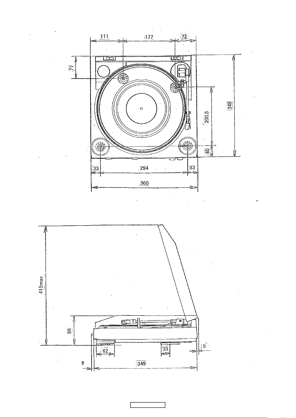
DIMENSION
3
DP-200USB
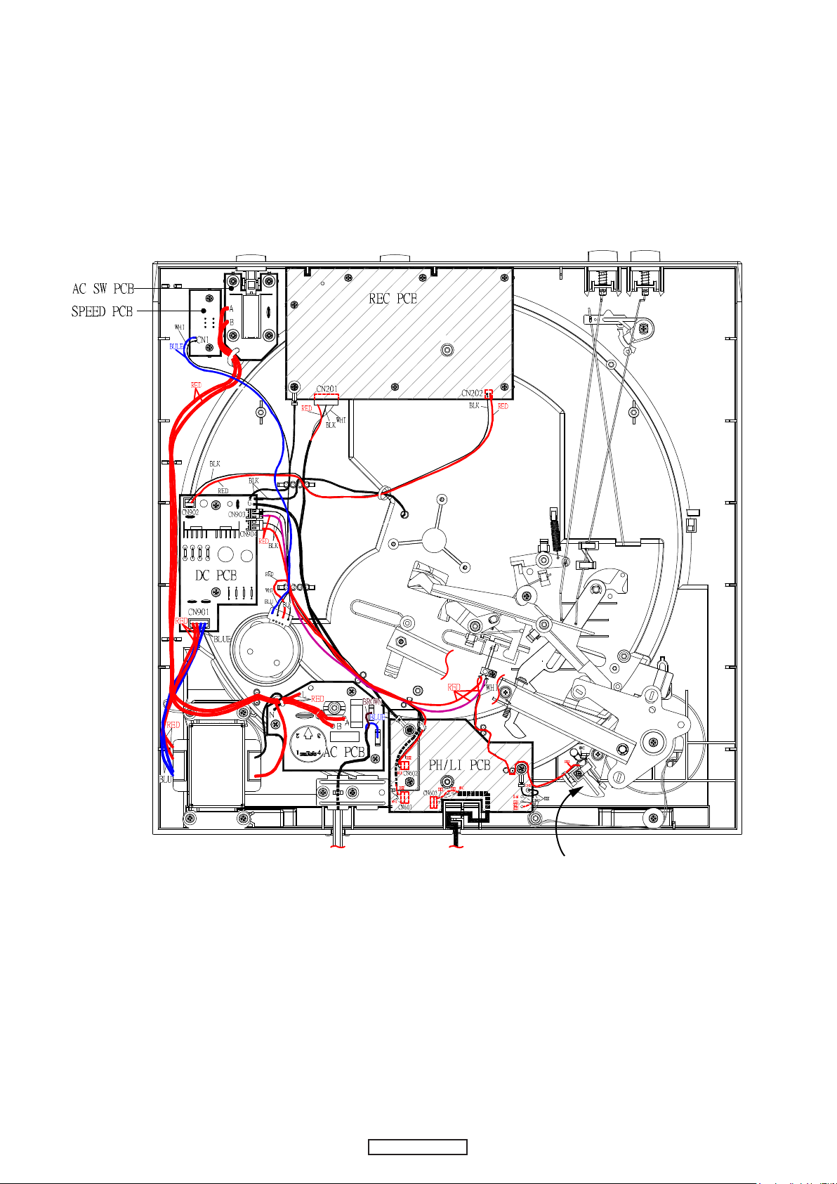
WIRE ARRANGEMENT
SW1
Leaf
SW
Leaf SWSgnal wireAC cord
4
DP-200USB
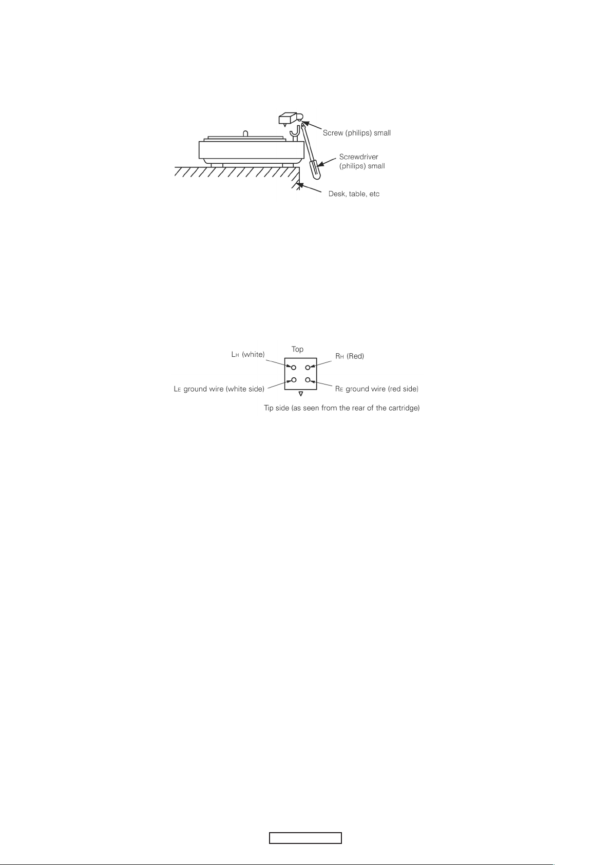
CARTRIDGE REPLACEMENT
(The cartrige forms a single body with the head shell. Use the following procedure to replace it.)
1.Remove the screw on the bottom of the head shell as shown in the diagram.
2. Rotate the entire head shell gently in both directions.
The neck of the head shell is attached to the pipe arm.
Turn it gently until the shell comes loose.
3. Carefully remove the head shell.
(Be careful not to break the lead wire.)
4. Remove the tip of the lead wire from the carridge terminal.
5. Install the new cartridge (with head shell).
The polarities are as shown on the diagram.
6. Assemble by following the removal procedure in reverse order.
Use one drop of Cemedyne #3000 to attach the neck of the head shell and the pipe arm.
5
DP-200USB
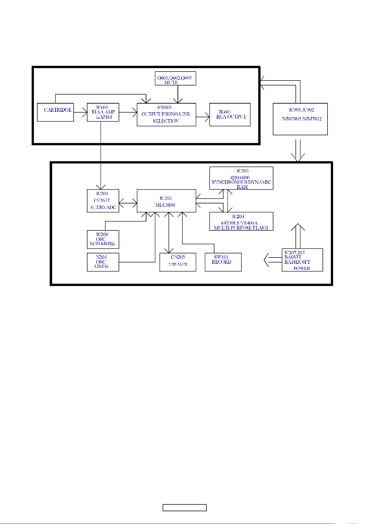
BLOCK DIAGRAMS
6
DP-200USB
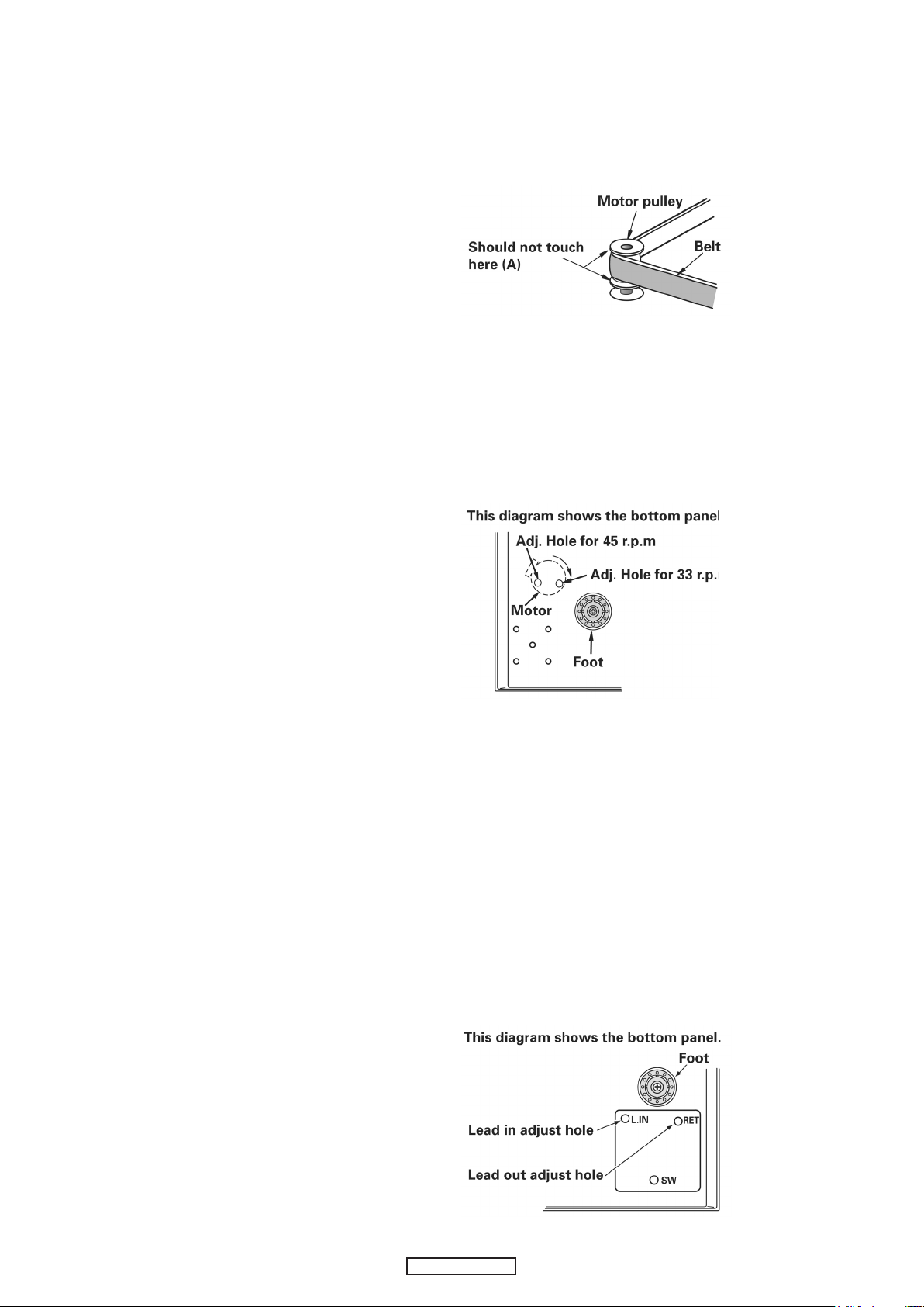
METHOD OF ADJUSTMENT
1.Relationship between belt and pulley.
Check that the belt is not touching the collars (A) of the motor
pulley. If it is, remove the turntable and reattach the belt at the
center of the turntable skirt.
2.Speed adjustment
If the speed is off, adjust it with the variable resistor on the
motor control board.
Adjust for 33 r.p.m rst, then set at 45 r.p.m and check.
After adjusting, check the two speeds (33 and 45 r.p.m) once
again.
3.Lead in and lead out adjustment
(1) Lead in
(test record: Hitachi HT-5 (30cm))
Check that the stylus lowers at 5 to 25 counts for both 17cm and 30 cm
records.
(2) Lead out
(Test record: Nippon Columbia EM-1001 (17cm))
Check that the pickup returns at 3 to 15 counts (3mm pitch).
If the counts are off, adjust as follows:
(a) Fasten the pickup to the arm rest.
(b) Insert a scrwedriver into the lead in or lead out adjustment holes and
adjust.
Lead in
Count increases when turned clockwise
・
Count decreases when turned counterclockwise
・
Lead out
Count increases when turned clockwise
・
Count decreases when turned counterclockwise
・
7
DP-200USB
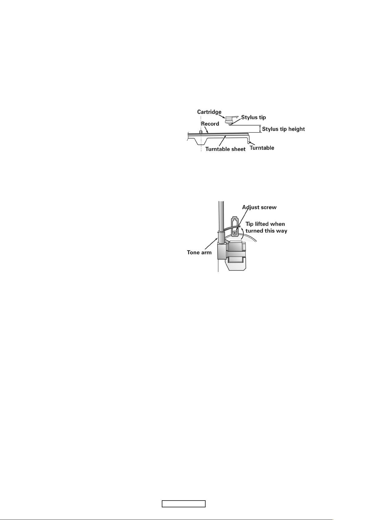
4.Stylus tip height adjustment
(1) Adjust the stylus tip height under standard conditions.
(Standard conditions: with the turntable, turntable sheet,
and record set)
(2) The stylus tip theight should be adjusted to about 6mm
when returned (5-7mm at the outermost position for 17cm
records).
(3) If the stylus tip is too high, sound may be distorted and the
stylus may not advance.
If it is too low, it may scratch the record when returning.
(4) Adjust using the lifter screw.
Turn clockwise to lower the stylus tip.
・
Turn counterclockwise to lift the stylus tip.
・
8
DP-200USB
SEMICONDUCTORS
AD5/EAD533AD6/EAD634AD7/EAD735AD8/EAD836AD9/EAD9
37
AD10/EAD1038AD11/EAD1139AD12/EAD12
40
BA0/EAD1341BA1/EAD14
42
LDQM/EAD15
43
UDQM/EAD1 6
44
SDSCN
45
VDD
46
VSS
47
CKE
48
RASN
49
IOVDD
50
IOVSS
51
SDCLK
52
CASN
53
WEN
54
EAD17/GP34
55
EAD18/GP35
56
EAD19/GP36
57
EAD20/GP37
58
EWEN
59
EOEN/GP38
60
ECSN
61
XI16EN/SPIDI
62
GP0163GP02
64
GP2797SCOR/GP2898BCLK/GP2999DATA/GP30
100
LRCK/GP31
101
SBDT/GP32
102
SBCK/GP33
103
GP23
104
VDD
105
VSS
106
NTRST
107
RESETN
108
IOVSS
109
XTI
110
XTO
111
TEST
112XI113XO114
IOVDD
115
USBD+
116
USBD-
117
IOVSS
118
PLL2VSS
119
FILTER2
120
PLL2VDD
121
PLL1VSS
122
FILTER1
123
PLL1VDD
124
ADIN5
125
ADIN4
126
ADIN3
127
ADIN2
128
Only major semiconductors are shown, general semiconductors etc. are omitted to list.
The semiconductor which described a detailed drawing in a schematic diagram are omitted to list.
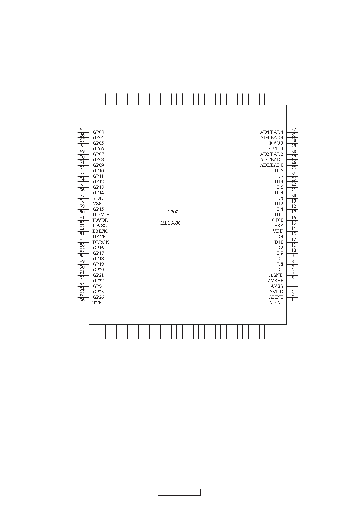
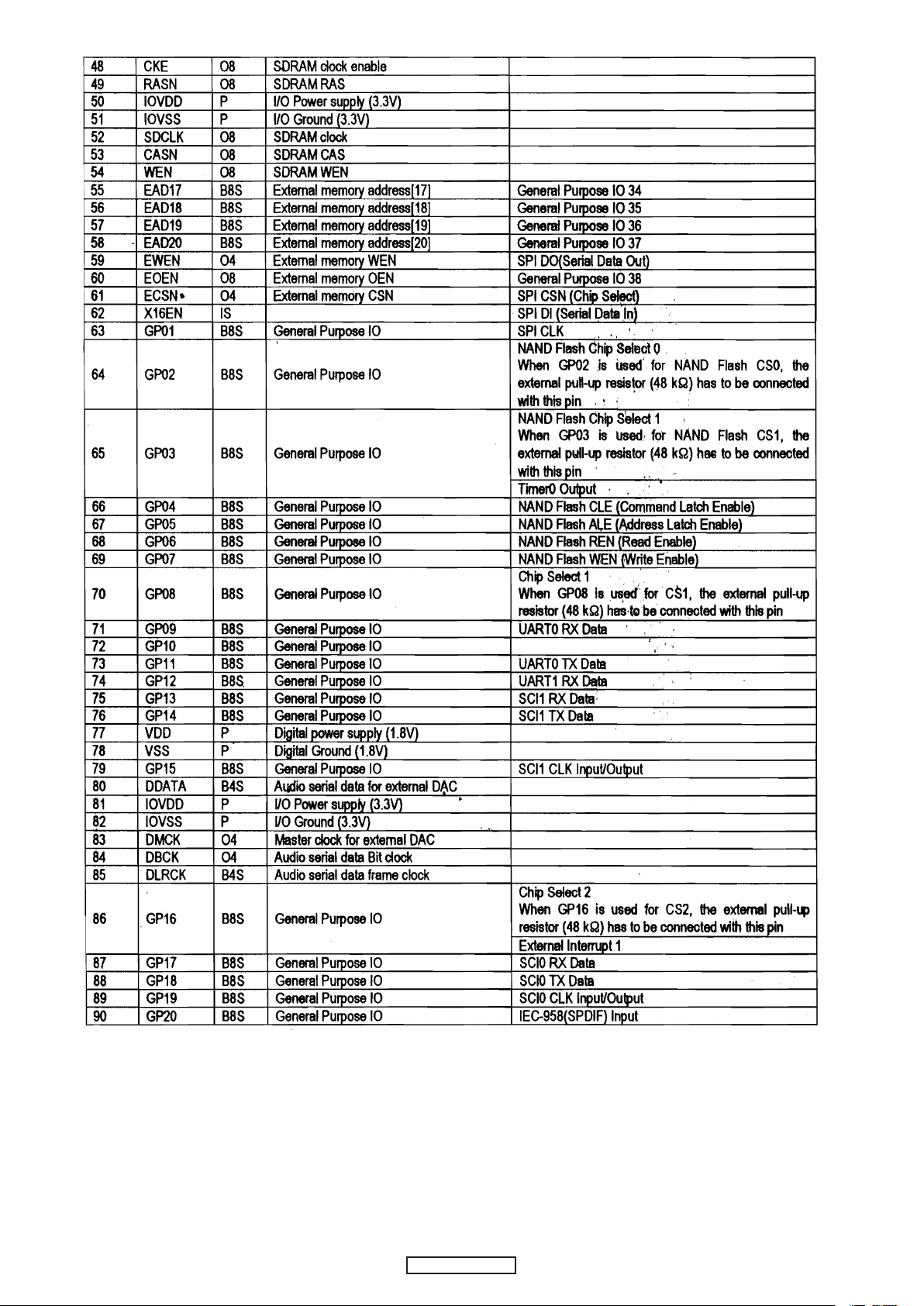
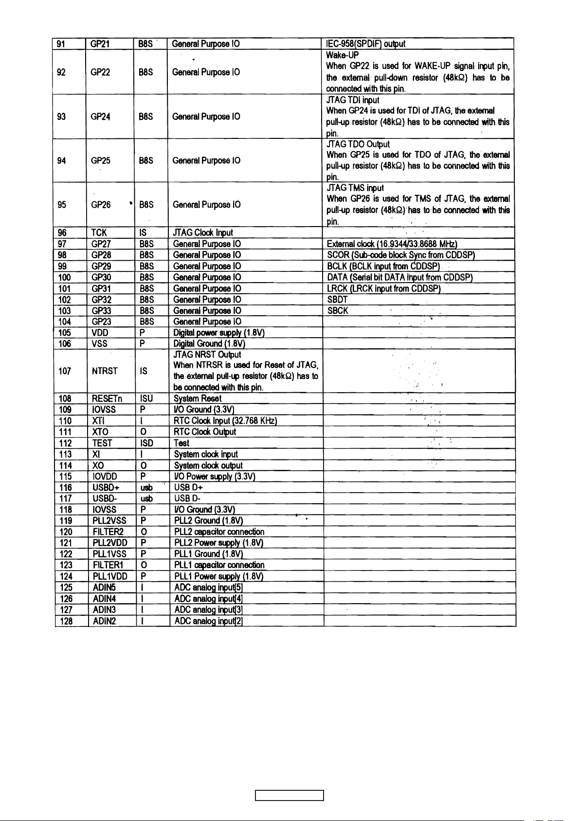
1. IC's
MLC3890 (IC202)
9
9
DP-200USB
DP-200USB
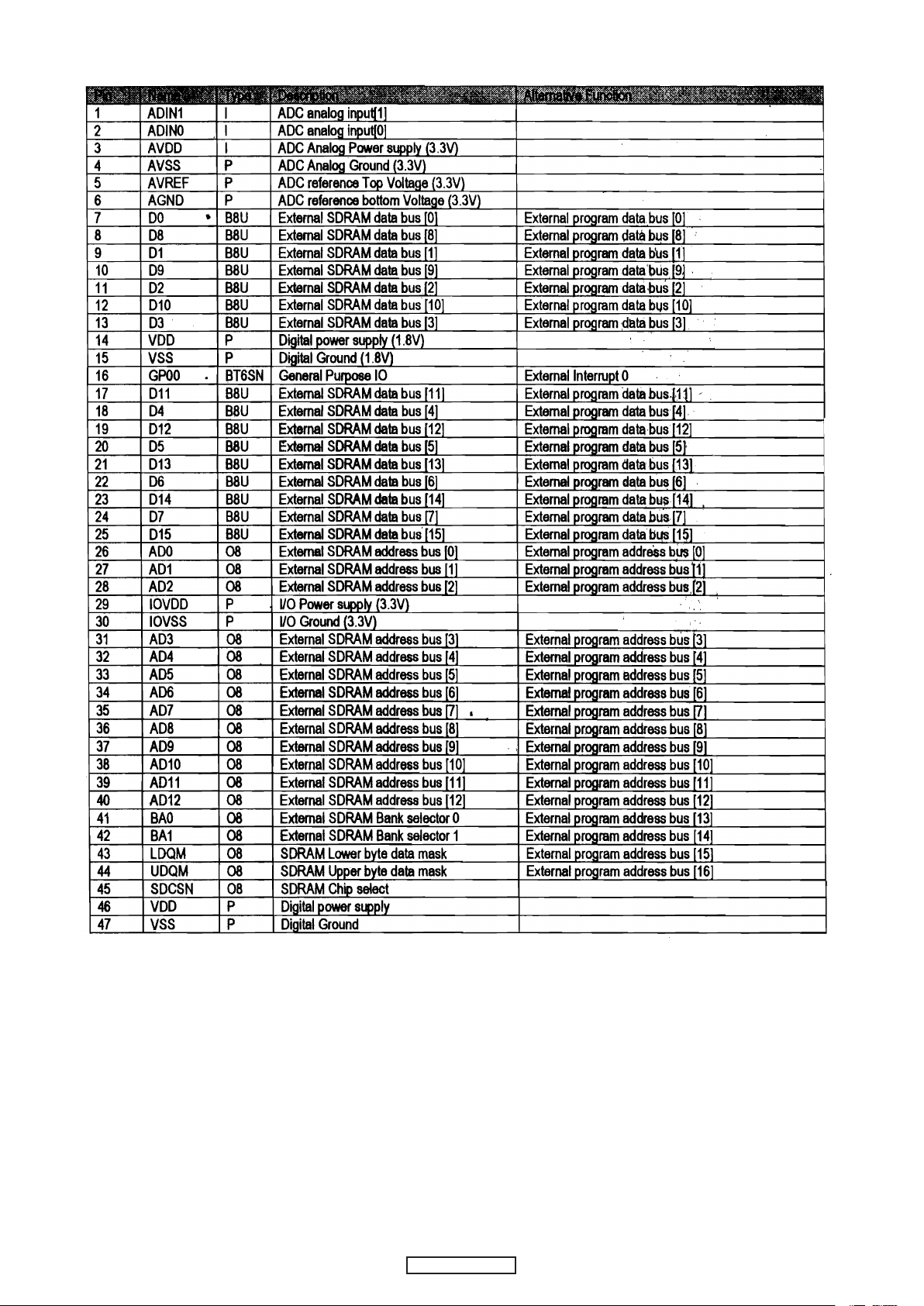
Terminal Function
10
10
DP-200USB
DP-200USB
11
11
DP-200USB
DP-200USB
12
12
DP-200USB
DP-200USB
Loading...