


DN-X1500
Table of contents
 Loading...
DJ MIXER
DN-X1500
OPERATING INSTRUCTIONS
MODE D’EMPLOI
FOR ENGLISH READERS PAGE 2 ~ PAGE 13
POUR LES LECTEURS FRANCAIS PAGE 14 ~ PAGE 22
2
CAUTION:
TO REDUCE THE RISK OF ELECTRIC SHOCK, DO NOT REMOVE COVER (OR
BACK). NO USER SERVICEABLE PARTS INSIDE. REFER SERVICING TO
QUALIFIED SERVICE PESONNEL.
The lightning flash with arrowhead symbol, within an equilateral triangle, is intended to
alert the user to the presence of uninsulated “dangerous voltage” within the product’s
enclosure that may be of sufficient magnitude to constitute a risk of electric shock to
persons.
The exclamation point within an equilateral triangle is intended to alert the user to the
presence of important operating and maintenance (servicing) instructions in the literature
accompanying the appliance.
WARNING: TO PREVENT FIRE OR SHOCK HAZARD, DO NOT EXPOSE THIS
APPLIANCE TO RAIN OR MOISTURE.
CAUTION:
1. Handle the power supply cord carefully
Do not damage or deform the power supply cord. If it
is damaged or deformed, it may cause electric shock
or malfunction when used. When removing from wall
outlet, be sure to remove by holding the plug
attachment and not by pulling the cord.
2. Do not open the top cover
In order to prevent electric shock, do not open the top
cover.
If problems occur, contact your DENON dealer.
3. Do not place anything inside
Do not place metal objects or spill liquid inside the DJ
mixer.
Electric shock or malfunction may result.
Please, record and retain the Model name and serial
number of your set shown on the rating label.
Model No. DN-X1500 Serial No.
This device complies with Part 15 of the FCC Rules.
Operation is subject to the following two conditions:
(1) This device may not cause harmful interference,
and (2) this device must accept any interference
received, including interference that may cause
undesired operation.
This Class B digital apparatus meets all requirements
of the Canadian Interference-Causing Equipment
Regulations.
Cet appareil numérique de la classe B respecte toutes
les exigences du Règlement sur le matériel brouilleur
du Canada.
CAUTION
TO PREVENT ELECTRIC SHOCK, MATCH
WIDE BLADE OF PLUG TO WIDE SLOT,
FULLY INSERT.
ATTENTION
POUR ÉVITER LES CHOCS ÉLECTRIQUES,
INTERODUIRE LA LAME LA PLUS LARGE
DE LA FICHE DANS LA BORNE
CORRESPONDANTE DE LA PRISE ET
POUSSER JUSQU’ AU FOND.
CAUTION
RISK OF ELECTRIC SHOCK
DO NOT OPEN
LABELS:
SAFETY INSTRUCTIONS
1. Read Instructions – All the safety and operating instructions
should be read before the product is operated.
2. Retain Instructions – The safety and operating instructions
should be retained for future reference.
3. Heed Warnings – All warnings on the product and in the
operating instructions should be adhered to.
4. Follow Instructions – All operating and use instructions
should be followed.
5. Cleaning – Unplug this product from the wall outlet before
cleaning. Do not use liquid cleaners or aerosol cleaners.
6. Attachments – Do not use attachments not recommended
by the product manufacturer as they may cause hazards.
7. Water and Moisture – Do not use this product near water –
for example, near a bath tub, wash bowl, kitchen sink, or
laundry tub; in a wet basement; or near a swimming pool;
and the like.
8. Accessories – Do not place this product on an unstable cart,
stand, tripod, bracket, or table. The product may fall,
causing serious injury to a child or adult, and serious
damage to the product. Use only with a cart, stand, tripod,
bracket, or table recommended by the manufacturer, or
sold with the product. Any mounting of the product should
follow the manufacturer’s instructions, and should use a
mounting accessory
recommended by the
manufacturer.
9. A product and cart
combination should be
moved with care. Quick
stops, excessive force,
and uneven surfaces may
cause the product and cart
combination to overturn.
10. Ventilation – Slots and openings in the cabinet are provided
for ventilation and to ensure reliable operation of the
product and to protect it from overheating, and these
openings must not be blocked or covered. The openings
should never be blocked by placing the product on a bed,
sofa, rug, or other similar surface. This product should not
be placed in a built-in installation such as a bookcase or rack
unless proper ventilation is provided or the manufacturer’s
instructions have been adhered to.
11. Power Sources – This product should be operated only
from the type of power source indicated on the marking
label. If you are not sure of the type of power supply to
your home, consult your product dealer or local power
company. For products intended to operate from battery
power, or other sources, refer to the operating instructions.
12. Grounding or Polarization – This product may be equipped
with a polarized alternating-current line plug (a plug having
one blade wider than the other). This plug will fit into the
power outlet only one way. This is a safety feature. If you
are unable to insert the plug fully into the outlet, try
reversing the plug. If the plug should still fail to fit, contact
your electrician to replace your obsolete outlet. Do not
defeat the safety purpose of the polarized plug.
13. Power-Cord Protection – Power-supply cords should be
routed so that they are not likely to be walked on or pinched
by items placed upon or against them, paying particular
attention to cords at plugs, convenience receptacles, and
the point where they exit from the product.
15. Outdoor Antenna Grounding – If an outside antenna or
cable system is connected to the product, be sure the
antenna or cable system is grounded so as to provide some
protection against voltage surges and built-up static
charges. Article 810 of the National Electrical Code,
ANSI/NFPA 70, provides information with regard to proper
grounding of the mast and supporting structure, grounding
of the lead-in wire to an antenna discharge unit, size of
grounding conductors, location of antenna-discharge unit,
connection to grounding electrodes, and requirements for
the grounding electrode. See Figure A.
16. Lightning – For added protection for this product during a
lightning storm, or when it is left unattended and unused
for long periods of time, unplug it from the wall outlet and
disconnect the antenna or cable system. This will prevent
damage to the product due to lightning and power-line
surges.
17. Power Lines – An outside antenna system should not be
located in the vicinity of overhead power lines or other
electric light or power circuits, or where it can fall into such
power lines or circuits. When installing an outside antenna
system, extreme care should be taken to keep from
touching such power lines or circuits as contact with them
might be fatal.
18. Overloading – Do not overload wall outlets, extension
cords, or integral convenience receptacles as this can result
in a risk of fire or electric shock.
19. Object and Liquid Entry – Never push objects of any kind
into this product through openings as they may touch
dangerous voltage points or short-out parts that could
result in a fire or electric shock. Never spill liquid of any
kind on the product.
20. Servicing – Do not attempt to service this product yourself
as opening or removing covers may expose you to
dangerous voltage or other hazards. Refer all servicing to
qualified service personnel.
21. Damage Requiring Service – Unplug this product from the
wall outlet and refer servicing to qualified service personnel
under the following conditions:
a) When the power-supply cord or plug is damaged,
b) If liquid has been spilled, or objects have fallen into the
product,
c) If the product has been exposed to rain or water,
d) If the product does not operate normally by following
the operating instructions. Adjust only those controls
that are covered by the operating instructions as an
improper adjustment of other controls may result in
damage and will often require extensive work by a
qualified technician to restore the product to its normal
operation,
e) If the product has been dropped or damaged in any way,
and
f) When the product exhibits a distinct change in
performance – this indicates a need for service.
22. Replacement Parts – When replacement parts are required,
be sure the service technician has used replacement parts
specified by the manufacturer or have the same
characteristics as the original part. Unauthorized
substitutions may result in fire, electric shock, or other
hazards.
23. Safety Check – Upon completion of any service or repairs
to this product, ask the service technician to perform safety
checks to determine that the product is in proper operating
condition.
24. Wall or Ceiling Mounting – The product should be mounted
to a wall or ceiling only as recommended by the
manufacturer.
25. Heat – The product should be situated away from heat
sources such as radiators, heat registers, stoves, or other
products (including amplifiers) that produce heat.
FIGURE A
EXAMPLE OF ANTENNA GROUNDING
AS PER NATIONAL
ELECTRICAL CODE
ANTENNA
LEAD IN
WIRE
GROUND
CLAMP
ELECTRIC
SERVICE
EQUIPMENT
ANTENNA
DISCHARGE UNIT
(NEC SECTION 810-20)
GROUNDING CONDUCTORS
(NEC SECTION 810-21)
GROUND CLAMPS
POWER SERVICE GROUNDING
ELECTRODE SYSTEM
(NEC ART 250, PART H)
NEC - NATIONAL ELECTRICAL CODE
3
ENGLISH
@1
@3
#2
#1
#3
q
w
e
r
t
y
!4
!2
!0
!1
!3
o
u
i
!6@0 !8!9 !5!7 !7
#5
#6
#5
#6
#5
#6
#5
#6
#4 #7
#0
@7
@8
@5
@6
@4
@9
@2
#9 #9 #9 #9
#8 #8 #8 #8
!6 !6 !6 !6
!0
Unit: mm
Unité: mm
FRANÇAIS
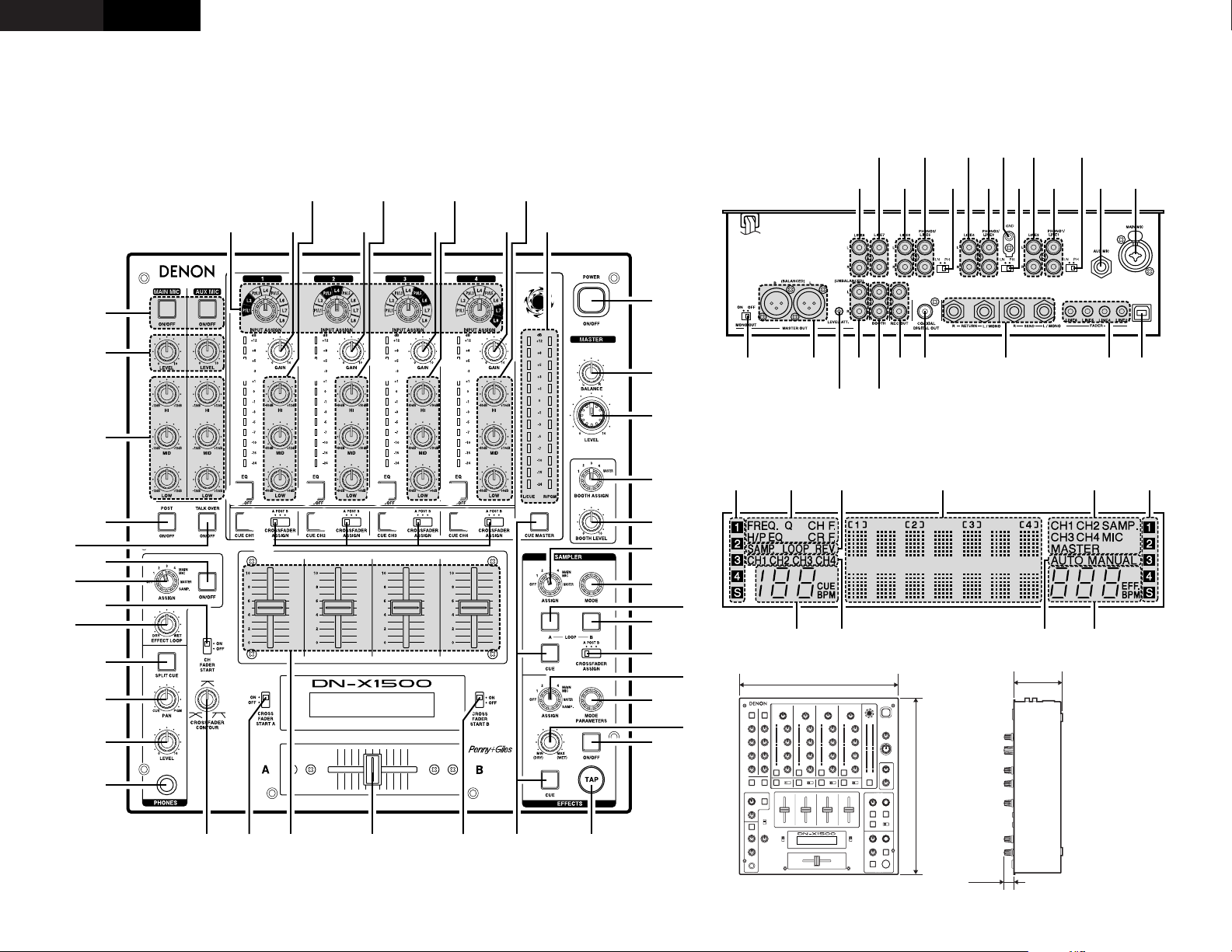
TOP PANEL DIAGRAM / SCHEMA DU PANNEAU SUPERIEUR
DISPLAY / AFFICHAGE
REAR PANEL DIAGRAM / SCHEMA DU PANNEAU ARRIERE
%5 %4 %2
%3 %1
%0 $9 $8 $7 $6
$0$0$0
$1 $0$1$3 $0
$1 $4 $5$2 $2
$2
^4^5 ^2^3
%6 %9 ^0 ^1%7 %8
327 (12-7/8”)
310 (12-13/64”)
90
(3-35/64”)
20
(25/32”)
4
• DECLARATION OF CONFORMITY
We declare under our sole responsibility that this
product, to which this declaration relates, is in
conformity with the following standards:
EN60065, EN55013, EN55020, EN61000-3-2 and
EN61000-3-3.
Following the provisions of 73/23/EEC,
89/336/EEC and 93/68/EEC Directive.
• ÜBEREINSTIMMUNGSERKLÄRUNG
Wir erklären unter unserer Verantwortung, daß
dieses Produkt, auf das sich diese Erklärung
bezieht, den folgenden Standards entspricht:
EN60065, EN55013, EN55020, EN61000-3-2 und
EN61000-3-3.
Entspricht den Verordnungen der Direktive
73/23/EEC, 89/336/EEC und 93/68/EEC.
• DECLARATION DE CONFORMITE
Nous déclarons sous notre seule responsabilité
que l’appareil, auquel se réfère cette déclaration,
est conforme aux standards suivants:
EN60065, EN55013, EN55020, EN61000-3-2 et
EN61000-3-3.
D’après les dispositions de la Directive
73/23/EEC, 89/336/EEC et 93/68/EEC.
• DICHIARAZIONE DI CONFORMITÀ
Dichiariamo con piena responsabilità che questo
prodotto, al quale la nostra dichiarazione si
riferisce, è conforme alle seguenti normative:
EN60065, EN55013, EN55020, EN61000-3-2 e
EN61000-3-3.
In conformità con le condizioni delle direttive
73/23/EEC, 89/336/EEC e 93/68/EEC.
QUESTO PRODOTTO E’ CONFORME
AL D.M. 28/08/95 N. 548
• DECLARACIÓN DE CONFORMIDAD
Declaramos bajo nuestra exclusiva
responsabilidad que este producto al que hace
referencia esta declaración, está conforme con
los siguientes estándares:
EN60065, EN55013, EN55020, EN61000-3-2 y
EN61000-3-3.
Siguiendo las provisiones de las Directivas
73/23/EEC, 89/336/EEC y 93/68/EEC.
• EENVORMIGHEIDSVERKLARING
Wij verklaren uitsluitend op onze
verantwoordelijkheid dat dit produkt, waarop
deze verklaring betrekking heeft, in
overeenstemming is met de volgende normen:
EN60065, EN55013, EN55020, EN61000-3-2 en
EN61000-3-3.
Volgens de bepalingen van de Richtlijnen
73/23/EEC, 89/336/EEC en 93/68/EEC.
• ÖVERENSSTÄMMELSESINTYG
Härmed intygas helt på eget ansvar att denna
produkt, vilken detta intyg avser, uppfyller
följande standarder:
EN60065, EN55013, EN55020, EN61000-3-2 och
EN61000-3-3.
Enligt stadgarna i direktiv 73/23/EEC, 89/336/EEC
och 93/68/EEC.
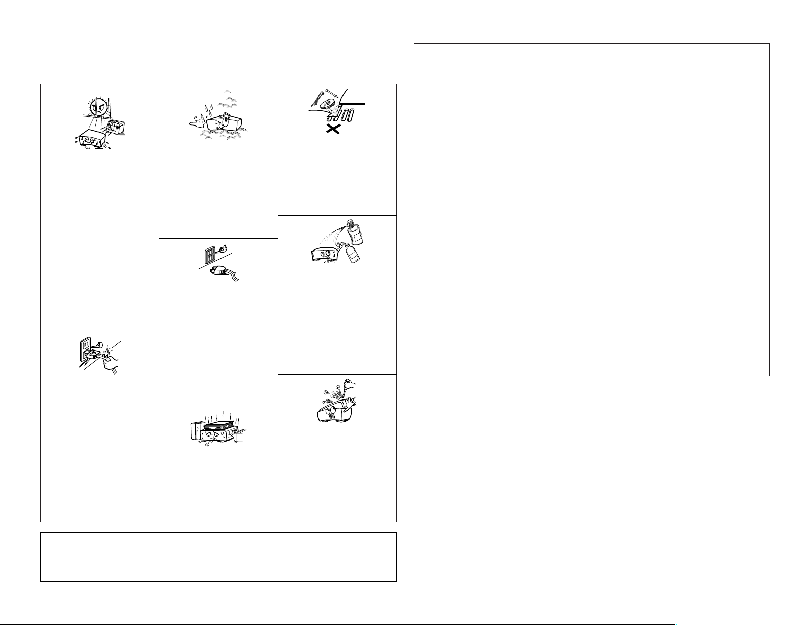
NOTE ON USE /
OBSERVATIONS RELATIVES A L’UTILISATION
•Avoid high temperatures.
Allow for sufficient heat dispersion when
installed on a rack.
•Vermeiden Sie hohe Temperaturen.
Beachten Sie, daß eine ausreichend
Luftzirkulation gewährleistet wird, wenn das
Gerät auf ein Regal gestellt wird.
• Eviter des températures élevées
Tenir compte d’une dispersion de chaleur
suffisante lors de l’installation sur une
étagère.
• Evitate di esporre l’unità a temperature alte.
Assicuratevi che ci sia un’adeguata
dispersione del calore quando installate
l’unità in un mobile per componenti audio.
• Evite altas temperaturas
Permite la suficiente dispersión del calor
cuando está instalado en la consola.
•Vermijd hoge temperaturen.
Zorg voor een degelijk hitteafvoer indien het
apparaat op een rek wordt geplaatst.
• Undvik höga temperaturer.
Se till att det finns möjlighet till god
värmeavledning vid montering i ett rack.
•Keep the set free from moisture, water, and
dust.
•Halten Sie das Gerät von Feuchtigkeit,
Wasser und Staub fern.
•Protéger l’appareil contre l’humidité, l’eau et
lapoussière.
•Tenete l’unità lontana dall’umidità, dall’acqua
e dalla polvere.
• Mantenga el equipo libre de humedad, agua
y polvo.
• Laat geen vochtigheid, water of stof in het
apparaat binnendringen.
•Utsätt inte apparaten för fukt, vatten och
damm.
• Do not let foreign objects in the set.
• Keine fremden Gegenstände in das Gerät
kommen lassen.
• Ne pas laisser des objets étrangers dans
l’appareil.
•E’ importante che nessun oggetto è inserito
all’interno dell’unità.
• No deje objetos extraños dentro del equipo.
• Laat geen vreemde voorwerpen in dit
apparaat vallen.
• Se till att främmande föremål inte tränger in i
apparaten.
• Do not let insecticides, benzene, and thinner
come in contact with the set.
• Lassen Sie das Gerät nicht mit Insektiziden,
Benzin oder Verdünnungsmitteln in
Berührung kommen.
• Ne pas mettre en contact des insecticides,
du benzène et un diluant avec l’appareil.
• Assicuratevvi che l’unità non venga in
contatto con insetticidi, benzolo o solventi.
• No permita el contacto de insecticidas,
gasolina y diluyentes con el equipo.
• Laat geen insektenverdelgende middelen,
benzine of verfverdunner met dit apparaat in
kontakt komen.
• Se till att inte insektsmedel på spraybruk,
bensen och thinner kommer i kontakt med
apparatens hölje.
• Unplug the power cord when not using the
set for long periods of time.
•Wenn das Gerät eine längere Zeit nicht
verwendet werden soll, trennen Sie das
Netzkabel vom Netzstecker.
• Débrancher le cordon d’alimentation lorsque
l’appareil n’est pas utilisé pendant de
longues périodes.
• Disinnestate il filo di alimentazione quando
avete l’intenzione di non usare il filo di
alimentazione per un lungo periodo di tempo.
• Desconecte el cordón de energía cuando no
utilice el equipo por mucho tiempo.
• Neem altijd het netsnoer uit het stopkontakt
wanneer het apparaat gedurende een lange
periode niet wordt gebruikt.
• Koppla ur nätkabeln om apparaten inte
kommer att användas i lång tid.
• Do not obstruct the ventilation holes.
•Die Belüftungsöffnungen dürfen nicht
verdeckt werden.
• Ne pas obstruer les trous d’aération.
• Non coprite i fori di ventilazione.
• No obstruya los orificios de ventilación.
• De ventilatieopeningen mogen niet worden
beblokkeerd.
• Täpp inte till ventilationsöppningarna.
• Handle the power cord carefully.
Hold the plug when unplugging the cord.
• Gehen Sie vorsichtig mit dem Netzkabel um.
Halten Sie das Kabel am Stecker, wenn Sie
den Stecker herausziehen.
•Manipuler le cordon d’alimentation avec
précaution.
Tenir la prise lors du débranchement du
cordon.
•Manneggiate il filo di alimentazione con cura.
Agite per la spina quando scollegate il cavo
dalla presa.
•Maneje el cordón de energía con cuidado.
Sostenga el enchufe cuando desconecte el
cordón de energía.
• Hanteer het netsnoer voorzichtig.
Houd het snoer bij de stekker vast wanneer
deze moet worden aan- of losgekoppeld.
• Hantera nätkabeln varsamt.
Håll i kabeln när den kopplas från el-uttaget.
• Never disassemble or modify the set in any
way.
•Versuchen Sie niemals das Gerät
auseinander zu nehmen oder auf jegliche Art
zu verändern.
• Ne jamais démonter ou modifier l’appareil
d’une manière ou d’une autre.
• Non smontate mai, nè modificate l’unità in
nessun modo.
• Nunca desarme o modifique el equipo de
ninguna manera.
• Nooit dit apparaat demonteren of op andere
wijze modifiëren.
•Ta inte isär apparaten och försök inte bygga
om den.
✽ (For sets with ventilation holes)
CAUTION
• The ventilation should not be impeded by covering the
ventilation openings with items, such as newspapers,
table-cloths, curtains, etc.
• No naked flame sources, such as lighted candles,
should be placed on the apparatus.
• Please be care the environmental aspects of battery
disposal.
• The apparatus shall not be exposed to dripping or
splashing for use.
• No objects filled with liquids, such as vases, shall be
placed on the apparatus.
ENGLISH
2 INTRODUCTION
Thank you very much for purchasing the DENON DN-X1500 DJ MIXER.
DENON proudly presents this advanced DJ MIXER to audiophiles and music lovers as a further proof of DENON’s
non-compromising pursuit of the ultimate in sound quality. The high quality performance and easy operation are
certain to provide you with many hours of outstanding listening pleasure.
– TABLE OF CONTENTS –
MAIN FEATURES ...............................................5
z
INSTALLATION ...................................................5
x
PART NAMES AND FUNCTIONS ................5 ~ 7
c
CONNECTIONS ..................................................8
v
SPECIFICATIONS................................................9
b
FADER START ..................................................10
n
EFFECTOR........................................................11
m
SAMPLER.........................................................12
,
PFL (Pre Fader Level) .......................................12
.
PRESET ............................................................13
⁄0
2 ACCESSORIES
Please check to make sure the following items
are included with the main unit in the carton:
1
MAIN FEATURES
1. Matrix input assignment
8 input sources is freely assignable to each
channels.
2. Penny & Giles Crossfader
Smooth and reliable mixing is excelled by Penny &
Giles Crossfader.
3. Sampler
On-board digital Sampler can record up to 8
seconds CD quality sound. You can seamlessly
Loop this Sampler or play it backwards
(REVERSE). The pitch and output level of Sampler
can be adjusted independently.
4. Internal Effector
Various sound effects can be performed. (DELAY,
ECHO, PAN, TRANS, FILTER, FLANGER, KEY)
5. Auto BPM counter, BPM Lock, TAP and Manual
BPM input
In addition to an Auto BPM counter and Tap
function, the DN-X1500 is also equipped with the
temporarily Lock function of the Auto BPM
counter and the Manual BPM input function.
6. Channel Fader and Crossfader Start
The CD player can be started or stopped simply by
increasing or decreasing the level of the Ch. Fader
or by using the Crossfader left to right or right to
left. (This function can only be used when the
DENON CD players DN-S3000, DN-S5000, DND4000 or etc. is connected to the DN-X1500.)
q Operating instructions.......................................1
7. Digital output
The DN-X1500 allows you to record directly to CDR, MiniDisc or a hard disk device through it’s
exclusive coaxial digital output.
The digital output maintains a constant 44.1 kHz
signal.
8. Enhanced SEND/RETURN terminals
8 LINE, 3 PHONO, 2 Microphone systems, 2
MASTER outputs, BOOTH output and REC output
are provided independently. Effect SEND/RETURN
terminals are also provided for a external effects
processor.
9. 3-Band equalizer/gain
LOW, MID, HI and GAIN controls are available on
every input channel.
10. Crossfader Contour
This feature allows adjusting the “shape” of the
Crossfader response from a gentle curve for
smooth, long running fades, to the steep pitch
required for top performance cut and scratch
effects.
11. Mic Post
This feature will pass the Mic signal into the
BOOTH, REC output and DIGITAL output signal
path.
In the OFF mode, the Mic signal will not be routed
through the above outputs.
12. PFL (Pre Fader Level)
This feature provides a means to adjust the input
level gain of each channel to avoid over loading. By
making this adjustment in advance will insure a
smooth transition between cross fades or channel
fades.
13. Preset functions
It is possible to customise the machine to your
preference by saving your favourite setting to
internal memory. For items found in the presets,
please see page 13.
3
PART NAMES AND FUNCTIONS
(1) Top panel
q Power operation switch (POWER)
• The power turns on when the button is
switched from the off position (
position (
• The power turns off when the button is
¢).
switched from the on position (
position (
£).
£) to the on
¢) to the off
w MASTER BALANCE control
• Adjusts the L/R balance of the MASTER output.
e MASTER LEVEL control
• Adjusts the level of the MASTER outputs.
r BOOTH ASSIGN switch
• Selects the source of the BOOTH output.
t BOOTH LEVEL control
• Adjusts the level of the BOOTH output.
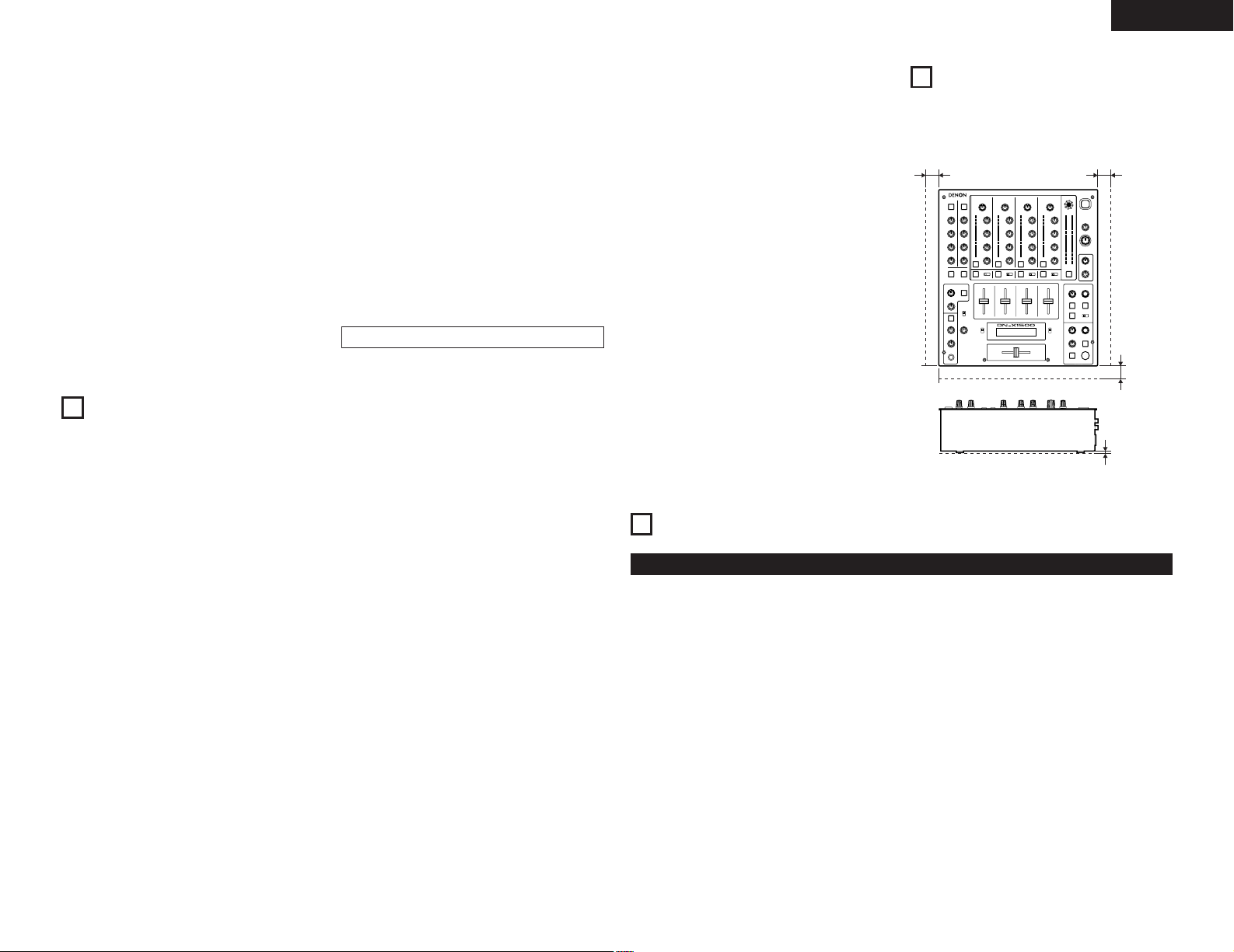
2
INSTALLATION
When the DN-X1500 is installed inside a coffin or DJ
booth, separate it from the foam (sponge), walls or
other equipment to improve heat radiation.
Min. 2 cm
Min. 2 cm
Min. 2 cm
Min. 3 mm
(Refer to page 3.)
y SAMPLER ASSIGN switch
• Use this to select the source for Sampler
recording.
u SAMPLER MODE knob
• Use this to set the Sampler playback mode or
edit the Sampler.
• Push this knob during the Sampler playback or
recording, the Sampler playback or recording is
stopped.
i SAMPLER A button
• Push this button, the Sampler recording or
playback starts.
o SAMPLER B button
• Use this to set the Sampler B point.
5

ENGLISH
LINE1
LINE2
LINE3
LINE4
LINE5
LINE6
LINE7
LINE8
• • • • •
INPUT ASSIGN INPUT ASSIGN
CH1 CH4
!0 CROSSFADER ASSIGN switch
A, B:
• The channel source is assigned to A or B of the
Crossfader.
POST:
• Select when you don’t assign the channel
source into the Crossfader.
!1 EFFECTS ASSIGN switch
• Use this to select the source of the internal
Effector.
!2 MODE PARAMETER knob
• Use this to set the effect mode and parameters.
!3 EFFECTS WET/DRY control
• Use this to adjust the ratio of original and
effected sound.
!4 EFFECTS ON/OFF button
• Use this to switch the internal Effector function
ON and OFF.
!5 TAP button
• TAP:
When you push this button repeatedly, the
AUTO mode turns off and starts measuring your
Beats Per Minute (BPM) by tapping.
• LOCK:
When this button is pressed once while the
auto BPM counter is operating, the data
measured by the auto BPM counter is locked.
• AUTO:
When pushing the TAP button for 1 second,
activates AUTO BPM mode.
The measured BPM is displayed in the BPM
display.
• INPUT BPM:
When the TAP button is pressed and held in for
more than 2 seconds, the BPM input mode is
set and the BPM value can be input directly with
the MODE PARAMETERS knob !2. When the
button is pressed again, the BPM input mode is
turned off.
!6 CUE buttons
• Pressing in any or all of the CUE buttons routes
the respective source to the headphone and
meter cue sections. Pressing multiple buttons
makes it possible to derive mixed sound from
the selected sources.
6
!7 CROSSFADER START A, B switches
• Use this to switch the Crossfader Start function
ON and OFF.
!8 Crossfader
• Controls the relative output level from the
summed A and B Mixes. When the fader is at its
far left, only the A Mix is heard from the
outputs. As the fader is moved toward the right,
the amount of B Mix is increased and the
amount of A Mix is decreased. When the fader
is centered, equal amounts of A and B Mixes
are routed to the outputs. Fully right is all B Mix
at the outputs.
!9 Source input fader (Ch. Fader)
• Controls the level of the selected Input.
@0 CROSSFADER CONTOUR control
• Allows adjusting the “shape” of the Crossfader
response from a gentle curve for smooth, long
running fades, to the steep pitch required for
top performance cut and scratch effects.
@1 HEADPHONE output jack
• Accepts 1/4” stereo headphone plugs.
@2 HEADPHONE LEVEL control
• Adjusts the volume for the headphones.
@3 HEADPHONE PAN control
• Serves two purposes…In the STEREO mode it
changes the relative levels of the Cue and
Program (CUE MASTER) mixed together in both
earcups. In the SPLIT CUE (MONO) mode it
changes the balance between the Mono Cue in
the left ear cup and the Mono Program
(MASTER) in the right.
@4 SPLIT CUE button
• In the STEREO mode, this button feeds
STEREO Program (CUE MASTER) and Cue to
both earcups, in the SPLIT CUE (MONO) mode,
the headphone circuit provides MONO Cue to
the left ear and MONO Program (MASTER) to
the right.
• In the STEREO mode, the meter indicates the
stereo level in the LEFT and RIGHT Master
Outputs. In the SPLIT CUE (MONO) mode,
mono Cue level is displayed on the Left meter
and mono Program (CUE MASTER) level is
displayed on the Right meter.
• In the SPLIT CUE (MONO) mode, the button is
lit.
@5 EFFECT LOOP WET/DRY control
• Use this to adjust the ratio of original and
effected sound.
@6 CH FADER START switch
• Use this to switch the Channel Fader Start
function ON and OFF.
@7 EFFECT LOOP ASSIGN switch
• Use this to select the source of the external
processor.
@8 EFFECT LOOP ON/OFF button
• Routes the assigned signal through the external
processor attached to the SEND/RETURN
connectors on the rear.
• When the EFFECT is ON, the button is lit.
(When the processor isn’t connected, the
button will blink when activated.)
@9 TALK OVER ON/OFF button
• Use this to switch the Talk Over function ON
and OFF.
• When the button is lit, level of signals except
Mics is attenuated.
• The Talk Over attenuation level can be adjusted
in the Preset mode.
NOTE:
When this button is pushed, volume changes
rapidly.
#0 MIC POST ON/OFF button
• Puts the Mic signals into the BOOTH, REC and
DIGITAL out signal path.
#1 MIC EQ controls
• Contour the frequency response of the MIC
input –12 dB to +12 dB.
At the center position, sound is flat.
#2 MIC LEVEL controls
• Adjusts the level of the Mic signal.
#3 MIC ON/OFF buttons
• When the button is lit, Mic signal is transferred
to output section, otherwise Mic input is muted.
#4 INPUT ASSIGN (Input selectors)
• Select any source from eight inputs
(PHONO1/LINE1, LINE2, PHONO2/LINE3,
LINE4, PHONO3/LINE5, LINE6, LINE7, LINE8)
for each channel independently.
• You also can assign the same input to several
channels for creative mixing.
#5 GAIN (Line input level controls)
• Adjusts the level of the selected input.
• You can adjust each GAIN volume to indicate
0dB on source level meter.
#6 Source EQ controls
• Contour the frequency response of the selected
inputs.
At the center position, sound is flat.
HI and MID:
• Adjusts the high-tone and mid-tone sound –40
dB to +10 dB.
LOW:
• Adjusts the low-tone sound –40 dB to +6 dB.
NOTE:
Clipping may occur if adjustments are set to
harsh.
#7 CUE MASTER level meter
• Displays the output level following MASTER
LEVEL adjustment.
• Can switch between two display mode. See
below @4.
#8 Source level meters
• Displays the input level after adjusted with
GAIN #5 and EQ #6 controls.
NOTE:
If this meter indicates over +12 dB, inputted
sound may be clipped.
#9 EQ ON/OFF buttons
• When this button is lit EQ is on, otherwise EQ is
bypassed.

ENGLISH
(2) Rear panel
$0 LINE2, 4, 6, 7, 8 input jacks
• These stereo pairs of unbalanced RCA jacks are
inputs for any line level device.
$1 PHONO1, 2, 3 / LINE1, 3, 5 input
jacks
• These stereo pairs of unbalanced RCA jacks are
inputs for a PHONO (RIAA) stage for magnetic
(MM) cartridges or a LINE stage suitable for any
device, such as a CD player.
$2 PHONO1, 2, 3 / LINE1, 3, 5 switches
• These switches change the input from PHONO
to a LINE level inputs.
• These switches set a LINE level inputs when
turntable is not connected.
$3 Phono ground screw (GND)
• This screws provide a place to connect the
ground wire from a turntable.
This terminal is exclusively for a turntable
grounding and not a safety earth ground.
$4 AUX MIC input jack
• Accepts an balanced microphone with 1/4” TRS
mono jacks.
• Pin layout: Tip=Hot Ring=Cold Sleeve=GND
$5 MAIN MIC input connector
• Neutrik combo jack.
• Accepts either a balanced microphone with an
XLR connector or a balanced microphone with
1/4” TRS mono jacks.
• Pin layout:
XLR: 1. GND 2. Hot 3. Cold
1/4” TRS: Tip=Hot Ring=Cold Sleeve=GND
$6 Maintenance connector
NOTE:
This connector can be used only for firmware
updating. Do not connect device, or may cause
damage.
$7 LINE2, 4, 6, 8 FADER output jacks
• Connect these jacks to the FADER input jacks of
DN-S3000, DN-S5000, DN-D4000 and etc. using
the 3.5 mm stereo mini cord.
$8 SEND / RETURN jacks
• These 1/4” TS mono jacks allow external
processing of the program signal.
• When connect monaural type effect processor,
use Lch input and output.
$9 DIGITAL OUT (COAXIAL) jack
• This RCA jack provides a digital output data. The
signal is unaffected by the MASTER LEVEL
control.
• We recommend using a 75 Ω/ohm RCA cord for
best digital transfer. (available from any
audio/video retailer)
%0 REC OUT jacks
• This stereo pair of RCA jacks provide a line level
output. The signal is unaffected by the MASTER
LEVEL control.
%1 BOOTH OUT jacks
• This stereo pair of RCA jacks provide a
unbalanced line level output with independent
top panel BOOTH LEVEL control.
%2 MASTER OUT (UNBALANCED)
jacks
• This stereo pair of RCA jacks provide a
unbalanced line level output.
• Connect these jacks to the unbalanced analog
input jacks on an amplifier or console.
%3 LEVEL ATT
(Master out level attenuator)
• Use this to attenuate the MASTER output level.
(–
~ 0 dB)
∞
• Reference is 0 dB.
%4 MASTER OUT (BALANCED)
connectors
• These XLR type connectors provide a balanced
line level output.
• Connect these connectors to the balanced
analog input connectors on an amplifier or
console.
• Pin layout: 1. GND 2. Hot 3. Cold
• Applicable connector:
NOTE:
Cannon XLR-3-31 or equivalent.
Do not short-circuit the hot or cold pin with the
GND pin.
%5 MASTER MONO OUT ON/OFF
switch
• When this switch is on, mixed L and R signal is
outputted from the MASTER OUT (Both
BALANCED and UNBALANCED).
(3) Display
%6 Crossfader A assign indicators
• This indicator shows channels of assigned
channel to Crossfader A side.
%7 Preset mode indicators
%8 Sampler mode indicators
SAMP.:
• The Sampler sound is recorded.
LOOP:
• Playing Sampler in Loop mode.
REV.:
• Reverse Sampler playback.
%9 Character display
• This displays various operational information,
etc..
• [ 1 ] : CH-1 indicator
[ 2 ] : CH-2 indicator
[ 3 ] : CH-3 indicator
[ 4 ] : CH-4 indicator
The number of assigned input source is
displayed on the character display under these
indicator.
^0 Effect assign indicators
• Selected Effector source is indicated here.
^1 Crossfader B assign indicators
• This indicator shows channels of assigned
channel to Crossfader B side.
^2 Effector BPM display
• This display indicates the BPM of the assigned
source.
^3 BPM mode indicators
AUTO:
• This indicator is lit, when the BPM mode is
AUTO BPM.
• This indicator is flashed, when the AUTO BPM
is locked.
MANUAL:
• This indicator is lit, when the BPM mode is
manual BPM input. You can input desired BPM
by MODE PARAMETER knob.
^4 Cue button indicators
• Channels of CUE selected are indicated.
^5 Cue BPM display (Auto count)
• This display indicates the BPM of the selected
channel.
NOTE:
BPM will not be displayed, if 2 or more channels
are selected.
7
Loading...