


 Loading...
|
|
|
|
|
|
|
|
|
Ver. 2 |
||
|
|
|
|
|
|
|
|
Please refer to the |
|||
|
|
|
|
|
|
|
|
MODIFICATION NOTICE. |
|||
|
|
|
|
|
|
|
|
|
|
|
|
|
|
SERVICE MANUAL |
|
|
|
|
|
||||
|
|
|
|
|
|
|
|
|
|
|
|
|
MODEL |
|
JP |
E3 |
E2 |
EK |
E2A |
E2C |
E1K |
EUT |
|
|
|
|
|
|
|
|
|
|
|
|
|
|
|
|
|
|
|
|
|
|
|
|
|
|
DN-X050 |
|
|
s3 |
s3 |
|
3 |
3 |
|
|
|
DJ MIXER
●For purposes of improvement, specifications and design are subject to change without notice.
●Please use this service manual with referring to the operating instructions without fail.
●Some illustrations using in this service manual are slightly different from the actual set.
|
●8
PROFESSIONAL BUSINESS COMPANY
X0359 V.02 DE/CDM 0802
SAFETY PRECAUTIONS
The following check should be performed for the continued protection of the customer and service technician.
LEAKAGE CURRENT CHECK
Before returning the unit to the customer, make sure you make either (1) a leakage current check or (2) a line to chassis resistance check. If the leakage current exceeds 0.5 milliamps, or if the resistance from chassis to either side of the power cord is less than 460 kohms, the unit is defective.
CAUTION Please heed the points listed below during servicing and inspection.
Heed the cautions!
Spots requiring particular attention when servicing, such as the cabinet, parts, chassis, etc., have cautions indicated on labels or seals. Be sure to heed these cautions and the cautions indicated in the handling instructions.
Caution concerning electric shock!
(1)An AC voltage is impressed on this set, so touching internal metal parts when the set is energized could cause electric shock. Take care to avoid electric shock, by for example using an isolating transformer and gloves when servicing while the set is energized, unplugging the power cord when replacing parts, etc.
(2)There are high voltage parts inside. Handle with extra care when the set is energized.
Caution concerning disassembly and assembly!
Though great care is taken when manufacturing parts from sheet metal, there may in some rare cases be burrs on the edges of parts which could cause injury if fingers are moved across them. Use gloves to protect your hands.
Only use designated parts!
The set's parts have specific safety properties (fire resistance, voltage resistance, etc.). For replacement parts, be sure to use parts which have the same properties. In particular, for the important safety parts that are marked z on wiring diagrams and parts lists, be sure to use the designated parts.
Be sure to mount parts and arrange the wires as they were originally!
For safety reasons, some parts use tape, tubes or other insulating materials, and some parts are mounted away from the surface of printed circuit boards. Care is also taken with the positions of the wires inside and clamps are used to keep wires away from heating and high voltage parts, so be sure to set everything back as it was originally.
Inspect for safety after servicing!
Check that all screws, parts and wires removed or disconnected for servicing have been put back in their original positions, inspect that no parts around the area that has been serviced have been negatively affected, conduct an insulation check on the external metal connectors and between the blades of the power plug, and otherwise check that safety is ensured.
(Insulation check procedure)
Unplug the power cord from the power outlet, disconnect the antenna, plugs, etc., and turn the power switch on. Using a 500V insulation resistance tester, check that the insulation resistance between the terminals of the power plug and the externally exposed metal parts (antenna terminal, headphones terminal, microphone terminal, input terminal, etc.) is 1MΩ or greater. If it is less, the set must be inspected and repaired.
CAUTION Concerning important safety parts
Many of the electric and structural parts used in the set have special safety properties. In most cases these properties are difficult to distinguish by sight, and using replacement parts with higher ratings (rated power and withstand voltage) does not necessarily guarantee that safety performance will be preserved. Parts with safety properties are indicated as shown below on the wiring diagrams and parts lists is this service manual. Be sure to replace them with parts with the designated part number.
(1)Schematic diagrams ... Indicated by the z mark.
(2)Parts lists ... Indicated by the z mark.
Using parts other than the designated parts could result in electric shock, fires or other dangerous situations.
2 DN-X050
|
|
|
|
|
|
|
|
|
|
|
|
|
|
|
|
|
|
|
||
(1) |
||
|
||
|
||
500V |
||
|
||
|
||
|
||
|
||
|
||
MΩ |
||
|
(2) には十分ご注意ください。
図、部品表にz
が維持されるとは、限りません。安全上の特性を持った部 品は、このサービスマニュアルの配線図、部品表につぎの ように表示していますので必ず指定されている部品番号 のものを使用願います。
(1) … z
(2) … z
3 DN-X050
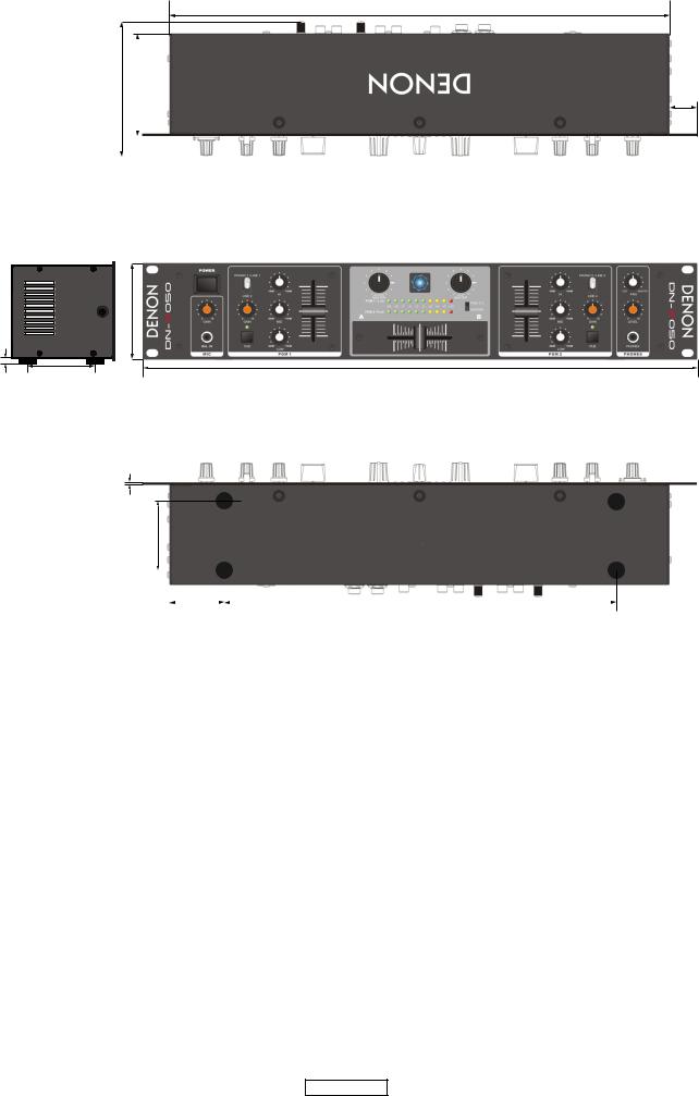
DIMENSION
434
 11
11
121.3 |
92 |
|
|
|
|
|
|
|
|
|
|
|
|
|
|
|
|
|
|
|
88 |
5 |
|
60 |
482 |
|
2
60
|
|
|
|
|
|
|
|
|
|
|
|
|
|
|
|
|
|
|
|
|
|
|
|
|
|
47 |
|
|
340 |
||
|
|
|
|||||
4 DN-X050
24
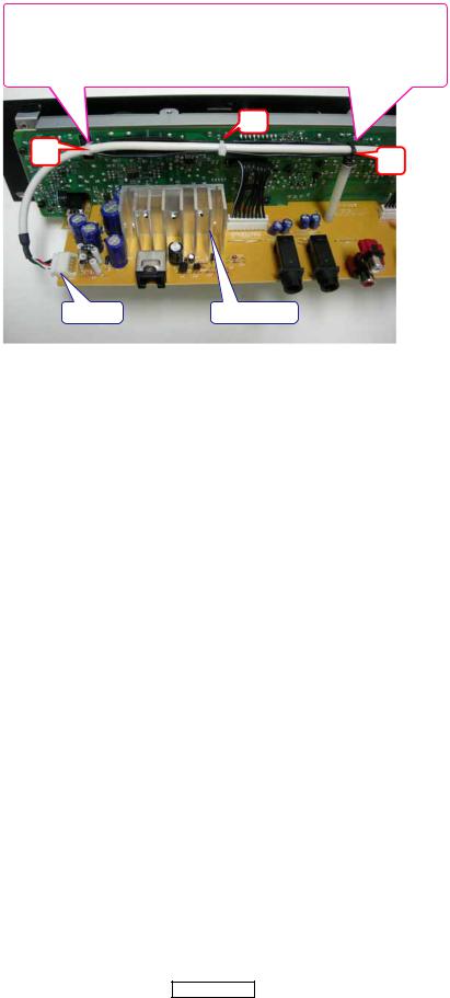
WIRE ARRANGEMENT |
|
If wire bundles are untied or moved to perform adjustment or |
|
parts replacement etc., be sure to rearrange them neatly as |
|
they were originally bundled or placed afterward. |
|
Otherwise, incorrect arrangement can be a cause of noise |
|
generation. |
|
CN05 A B C
Fasten the CN05 connector cord in a clamp band atA , B and C positions not to touch the heat sink.
B
A
C
CN05 |
HEAT SINK |
5 DN-X050
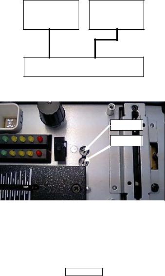
PGM LEVEL METER ADJUSTMENT PROCEDURE
(a) preparation
•S.G : Signal generator
•V.V : Voltmeter or AUDIO analyzer
•Bonding material : Adhesive or other materials.
(b)Connection and Adjustment
(1)Connect S.G to PHONO 1/LINE 1 L ch input at the Rear Panel.
(2)Connect V.V to MASTER RCA (UN BALANCED) L ch output at the Rear Panel.
(3)Snap Input Switch at the Front Panel toward PHONO 1/ LINE 1 and turn MASTER Volume and GAIN Volume to MAX.
(4)PGM1 EQ (LOW,MID,HIGH) Volume to the centre position and CROSSFADER Volume to left-hand edge position to adjust the level of S.G signal (1kHz). And then adjust V.V, which is connected to MASTER RCA(UNBALANCED) output, to 1V(0dB).
(5)Adjust VR501 on the MIXER board to light up the +2dB LED brightly.
(6)For adjusting R ch, connect S.G and V.V to R ch. Repeat the procedure (1)~(5) and adjust VR502.
Apply an appropriate amount of the bondig material to VR501 and VR502 after adjustment.
S.G
PGM LEVEL METER
(a)
S.G
V.V AUDIO analyzer
(1)PHONO 1/LINE 1 L ch S.G
(2)MASTER RCA(UN BALANCED) L ch V.V
(3)PHONO 1/LINE 1
MASTER Volume GAIN Volume MAX
(4)PGM 1 EQ LOW,MID,HIGH VolumeCROSSFADER Volume MASTER RCA(UN BALANCED) V.V 1V(0dB) S.G 1kHz
(5)+2dB LED MIXERVR501
(6)Rch R ch (1) (5)VR502
VR501 VR502
V.V
Voltmeter or
AUDIO analyzer
DN-X050
VR501
VR502
6 DN-X050

BLOCK DIAGRAM
|
+36/-0dB PREAMP |
PH1/LN 1 |
|
(-50/-14dBV) |
(-14dBV) |
|
|
|
|
CH1 GAIN |
|
|
CHANNEL EQ |
|
|
|
|
|
|
+14dB AMP |
|
LOW |
MID |
2 |
1 |
1 |
A |
|
|
|
|
|
|
|
3 |
|
|
3 |
3 |
||
|
|
|
C1 |
2 |
(-14dBV) |
(0dBV) |
2 |
2 |
|
|
2 |
|
|
|
|
|
|
|
|
|
|
1 |
|
|
1 |
1 |
LINE2
(-14dBV)
PH2/L N3 |
+36/+0dB PREAMP |
|
|
|
|
|
|
|
(-50/-14dBV) |
|
(-14dBV |
|
|
|
|
|
|
|
|
|
|
CH1 GAIN |
|
|
CHANNEL EQ |
|
|
|
|
|
|
+14dB AM P |
|
LOW |
MID |
|
2 |
1 |
1 A |
3 |
|
|
3 |
3 |
|
|
|
|
|
||||
|
|
|
C1 |
2 |
(-14dBV) |
(0dBV) |
2 |
2 |
|
|
|
2 |
|
|
|
|
|
|
|
|
|
1 |
|
|
1 |
1 |
LINE4 |
|
|
|
|
|
|
|
|
(-14dBV) |
|
|
|
|
|
|
|
|
|
|
|
|
MIC LEVEL |
|
|
|
|
|
+40dB PREAMP |
|
|
+14dB AMP |
|
|
|
|
|
|
|
MIC IN |
|
|
|
3 |
|
|
|
|
|
|
|
|
|
L |
3 |
(-54dBV) |
(-14dBV) |
2 |
(-14dBV) |
(0dBV) |
R |
2 |
|
|
|
|
|
G 1 |
|
|
1 |
|
|
|
|
|
|
|
|
||
|
|
CUE1 |
|
|
|
|
|
|
|
|
|
|
|
|
|
1 |
2 |
|
|
|
|
|
|
|
|
|
|
|
|
CH1 FADER |
|
CUE PAN |
|
|
UE LEVEL |
|
|
|
|
|
|
HI |
EQ AMP |
|
(0dBV) |
|
|
|
|
|
+6.7dB AMP |
|
|
|
|
3 |
|
3 |
|
3 |
|
|
3 |
|
|
|
|
|
PHONES OUT |
2 |
(0dBV) |
2 |
|
2 |
(0dBV) |
2 |
(-0.5dBV) |
(+6.2dBV) |
Ro |
(0dBV) |
|
||
|
|
|
|||||||||||
1 |
|
1 |
|
1 |
|
|
1 |
|
|
|
|
|
|
|
|
E 2 |
|
|
|
|
|
|
|
|
|
|
|
|
|
CUE 2 |
|
|
|
|
|
|
|
|
|
|
|
|
|
1 |
2 |
|
|
|
|
|
|
|
|
|
|
|
|
|
|
|
|
|
|
|
|
+1.78dB AMP |
|
|
|
|
|
|
|
|
|
|
|
|
|
|
|
|
(+4dBm) |
|
|
|
3 |
|
BALANCE |
|
MASTER LEVEL |
+1.43dB AMP |
|
|
|
||
|
|
|
|
|
|
|
|
|
|
|
|
|
|
|
|
|
2 |
|
|
|
|
|
|
|
|
|
MASTER OUT |
|
|
|
|
|
3 |
|
3 |
|
|
|
|
Ro |
|
|
|
|
1 |
|
|
|
|
|
|
|
|
|
|
|
|
|
(0dBV) |
2 |
(-0.6dBV) |
2 |
(-0.6dBV) |
(+0.83dBV) |
|
|
(0dBV) |
||
|
|
|
|
|
|
||||||||
|
|
|
|
|
1 |
|
1 |
|
|
|
|
|
|
|
|
|
CROSSFADER |
|
|
|
|
|
|
|
|
|
|
|
|
|
|
|
|
|
|
PFL/MA |
|
|
|
|
|
|
|
|
|
|
|
|
|
1 A |
|
|
|
|
|
|
|
|
|
|
|
|
|
|
C1 |
LED DRIVER |
LEVEL METER |
||
|
|
|
|
|
|
|
|
|
|
|
|
||
|
|
|
|
|
|
|
|
2 |
|
|
|
|
|
|
|
|
|
|
|
|
|
|
|
(-10.2dBV) |
|
|
|
|
|
|
|
|
|
|
|
3 B |
|
|
|
|
|
|
|
|
|
|
|
|
|
|
C2 |
|
|
|
|
|
|
|
|
|
|
|
|
4 |
|
|
|
|
|
|
|
CH2 FADER |
|
|
|
|
|
|
|
|
|
|
|
HI |
EQ AMP |
|
3 |
|
3 |
2 |
(0dBV) |
2 |
1 |
|
1 |
5V
15V
|
POWER |
AC IN |
SUPPLY |
|
-15V
7 DN-X050

LEVEL DIAGRAM
10dBV |
|
|
|
|
|
|
|
|
|
0dBV |
|
|
|
|
|
|
|
|
|
-10dBV |
|
|
|
|
|
|
|
|
|
|
LINE INPUT |
|
|
|
|
|
|
|
|
-20dBV |
|
|
|
|
|
|
|
|
|
-30dBV |
|
|
|
|
|
|
|
|
|
-40dBV |
|
|
|
|
|
|
|
|
|
-50dBV |
PHONO INPUT |
|
|
|
|
|
|
|
|
|
|
|
|
|
|
|
|
|
|
|
MIC INPUT |
|
|
|
|
|
|
|
|
-60dBV |
|
|
|
|
|
|
|
|
|
-70dBV |
|
|
|
|
|
|
|
|
|
-80dBV |
|
|
|
|
|
|
|
|
|
|
|
|
|
|
Minimum Volume |
|
Minimum Volume |
|
Minimum Volume |
|
|
|
|
|
|
|
|
||
-90dBV |
|
|
|
|
|
|
|
|
|
|
INPUT |
PRE. |
. AMP |
MIC GAIN |
EQ |
CUE MIX |
MIX |
CUE LEVEL |
OUTPUT |
|
|
|
|
INPUT GAIN |
|
FADER |
|
MASTER LEVEL |
|
HEADPHONE OUT BALANCED OUT
UNBALANCED OUT
8 DN-X050
Loading...