


I m p o r t a n t s a fe g u a rd s
•Use this appliance only as described in this instruction manual.
As with any electrical appliance, the instructions aim to cover as many eventualities as possible. Caution and common sense should be used when operating and installing this air conditioner.
•This appliance has been manufactured to cool and dehumidify domestic environments and should not be used for other purposes.
•It is dangerous to alter or modify the unit's characteristics in any way.
•The appliance must be installed in line with the relevant national legislation.
•Should repairs be necessary, contact the nearest authorized De’Longhi Repair Service Center. Unauthorized Delonghi servicing can be dangerous.
•This appliance is to be used by adults only; keep away from children.
•In the case that the power cord becomes damaged, this must be substituted only by specialized personnel authorized by the manufacturer, to protect against fire.
•Always ensure the appliance is grounded. If you have any doubts check with a qualified electrician.
•We strongly discourage the use of an extension cord due to potential safety hazards. For temporary situations, use only CSA certified and UL Listed 3-wire grounded extension cord, rated 15 A, 125 V.
•Before cleaning or maintenance operations, always unplug the unit from the outlet.
•Do not pull on or place strain on the power cord when moving the appliance.
•The appliance should not be installed where the atmosphere may contain combustible gases, oil or sulphur, or near heat sources.
•Do not rest hot or heavy objects on the appliance.
•Clean the filters at least once a week.
•Avoid using heaters near the unit.
•The unit should be transported in a vertical position. If this is not possible secure the unit at an angle, do not lie it horizontally.
•Before transporting the unit, drain the unit. After transportation, wait at least 1 hour before switching the unit on.
•The packaging materials can be recycled. You are therefore recommended to place them in the special containers for differentiated waste collection.
•This appliance is fitted with a special safety device. When the compressor switches off, this device prevents it from switching on again for at least 3 minutes.
•WARNING: Handling the cord on this product will expose you to lead, a chemical known to the State of California to cause [cancer, and] birth defects or other reproductive harm. Wash hands after handling.
SAVE THESE INSTRUCTIONS
THIS PRODUCT IS FOR HOUSEHOLD ONLY
DESCRIPTION
1 |
air outlet grille |
11 wall flange |
|
2 |
control panel |
12 |
air exhaust hose |
3 |
castors |
13 |
accessory for wall mounting |
4 |
handles |
14 |
window bracket grille |
5 |
filter |
15 |
window bracket cap |
6 |
evaporator air intake grille |
16 |
window bracket |
7 |
air exhaust hose housing |
17 |
6 screws |
8 |
condenser air intake grille |
18 |
window outlet |
9 |
power cable |
19 |
rubber pipe |
10 drainage hose |
20 |
remote control |
|
4
Pre p a r i n g fo r u s e
ELECTRICAL CONNECTIONS |
|
||
Before plugging the appliance into the mains socket, check that: |
GB |
||
• The mains power supply corresponds to the value indicated on the rating plate on the back of the appliance; |
|||
|
|||
• The mains socket and electrical circuit are adequate for the appliance; |
|
||
• The mains socket matches the plug. If this is not the case, have the plug replaced; |
|
||
• The mains socket is adequately earthed. Failure to follow these important safety instructions absolves the |
|
||
manufacturer of all liability. |
|
||
|
|
||
The power cable must be replaced by a qualified professional only. |
|
|
|
|
|
|
|
The instructions below will enable you to prepare your air conditioner for operation as efficiently as possible.
Before use, make sure the air intake and outlet grilles are unobstructed.
AIR-CONDITIONING WITHOUT INSTALLATION
Just a few simple steps and your comfort is ensured with your air conditioner:
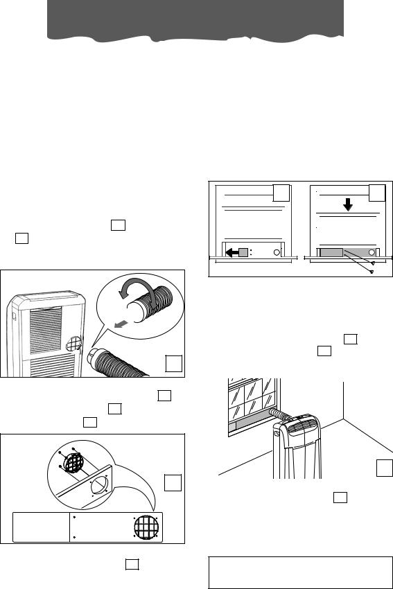
• Fit the air exhaust hose 12 in the housing
7 at the back of the appliance. Insert it as shown in figure A.
2
1 
A
Sash window
•Attach the window bracket grille 14 to the window bracket 16 with the four
screws provided 17 (fig. B).
B |
•Open the window.
•Place the window bracket 16 in the window, extending it to fit the width of the window (fig. C).
C |
D |
•Once the bracket is extended, it can be locked into his width by tightening the two screws provided.
•Close the window (fig. D).
•Place the air conditioner near the window. Insert the exhaust hose 12 into the window bracket grille 14 (fig. E). Make sure the air exhaust hose is unobstructed.
E
•When not used, the window bracket can be closed off with the cap 15 provided.
Keep the air hoses as short and free of curves as possible to avoid constrictions.
5

Pre p a r i n g fo r u s e
French window
•Attach the window outlet 18 to the air exhaust hose 12 (fig. F)..
2 1
F
•Open the French window slightly and position the outlet 12 . as shown in figure G
G |
Keep the air hoses as short and free of curves as possible to avoid constrictions.
SEMI-PERMANENT INSTALLATION
If required, your appliance can also be installed semi-permanently (Fig. H).
|
|
hes |
|
inc |
|
.8 |
m |
|
11 |
|
|
|
|
c |
|
30 |
|
11,8 inches |
|
D |
30 cm |
|
|
Proceed as follows:
•Drill a hole (ø134mm) in an outside wall or through a window pane.
Respect the height and dimensions of the hole given in figure I.
134 5,27 in. |
in the window |
in the wood- |
in the wall: you are |
||||||
pane |
|
|
en kickboard |
recommended to |
||||
|
|
|
|
of a French |
insulate |
the |
sec- |
|
|
I |
|
|
window |
|
tion of |
wall |
using |
|
|
|
|
|
suitable insulation. |
|||
• |
Fit the wall flange 11 |
into the hole. |
|
|||||
• Fit the air exhaust hose |
7 in the relevant |
|||||||
|
hose located on the rear side of the appli- |
|||||||
|
ance. (fig. A page 5). |
|
|
|
||||
• |
Remove |
|
|
|
|
J |
||
|
the |
plas- |
|
|
|
|
||
|
tic end of |
|
|
|
|
|
||
|
the |
hose |
|
|
1 |
|
|
|
|
12 |
b |
y |
|
|
|
|
|
|
|
|
|
|
|
|||
|
unscrew- |
|
|
|
|
|
||
|
ing it and |
|
|
2 |
|
|
||
|
in |
|
its |
|
|
|
|
|
|
p l a c e |
|
|
|
|
|
||
|
screw the |
|
|
|
|
|
||
|
w |
a l |
l |
|
|
|
|
|
|
mounting accessory |
13 |
(fig. J). |
|
|
|||
•Fit the end of the hose 12 to the wall flange 11 as shown in
fig. K.
|
MAX 39.37 inches |
K |
|
|
|
|
MAX100 cm |
|
|
|
|
|
|
|
 MIN 13.77 inches
MIN 35 cm
When the hose 12 is not fitted, the hole can
be closed with the flange cap.
NOTE: When installing the air conditioner semi-permanently, you should leave a door slightly open (as little as 1 cm) to guarantee correct ventilation.
6
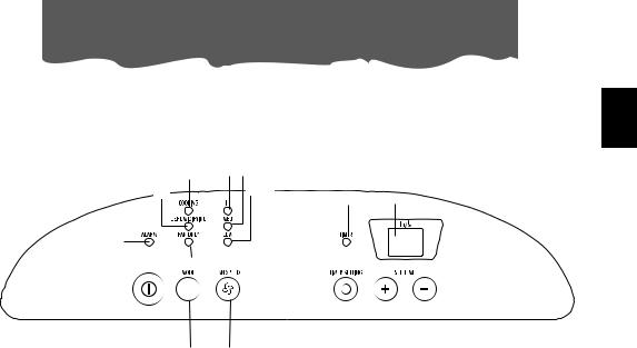
Control panel
THE CONTROL PANEL
GB
|
O I L |
|
|
P |
M |
G |
|
H |
|||
|
|||
Q |
|
|
|
|
N |
|
|
|
|
|
|
|
|
|
|
|
|
|
|
|
|
|
|
|
|
|
|
|
|
|
|
|
A |
|
B |
|
C |
|
|
E |
|
F |
|||
|
|
D |
|
|||||||||
|
|
|
|
|
|
|||||||
|
|
|
|
|
|
|
|
|
|
|
|
|
DESCRIPTION OF THE CONTROL PANEL
AON/OFF button
BMODE selection button
Air conditioning, dehumidifying, fan.
CFan speed selection button (HIGH/MED/LOW)
DTimer button
EProgrammed operation increase temperature/time button
FProgrammed operation decrease temperature/time button
GDisplay Displays the temperature values set and the programmed operating time
HTimer in operation indicator light
I/L/M Fan speed lights
NFan mode light
OAir-conditioning mode light
PDehumidifying mode light
QAlarm light
7
 Loading...