


PAC 40
Istruzioni per l’uso . . . . . . . . . . . . . . . . . . . . . . . . . . . . . . . . . . . . . . . .pag. 1
Use and maintenance manual . . . . . . . . . . . . . . . . . . . . . . . . . . . . . . .pag. 13
Mode d’emploi et d’entretien . . . . . . . . . . . . . . . . . . . . . . . . . . . . . . . .pag. 25
Bedienungsanleitung . . . . . . . . . . . . . . . . . . . . . . . . . . . . . . . . . . . . .S. 37
Gebruiksaanwijzing . . . . . . . . . . . . . . . . . . . . . . . . . . . . . . . . . . . . . . .pag. 49
Instrucciones de uso . . . . . . . . . . . . . . . . . . . . . . . . . . . . . . . . . . . . . .pag. 61
Manual de instruções . . . . . . . . . . . . . . . . . . . . . . . . . . . . . . . . . . . . .pag. 73
PAC40 5-07-2001 12:36 Pagina 1
Condizionatore d’aria
PAC 40
Istruzioni per l’uso
PAC40 5-07-2001 12:36 Pagina 1
2
PRESENTAZIONE
Il nuovo PAC 40 è un climatizzatore a controllo
elettronico molto versatile perchè può essere
usato per condizionare (automaticamente o
manualmente) durante la stagione estiva.
E’ un condizionatore del tipo split costituito da due
unità: una interna (che funziona all’interno del-
l’ambiente) e una esterna (da installare all’esterno
dell’ambiente). Le due unità vengono fornite già
collegate tra di loro da una guaina (3 metri circa)
contenente le connessioni frigorifere, i collega-
menti elettrici ed il tubicino scarico condensa.
Questo apparecchio è inoltre provvisto della fun-
zione SLEEP. Questa funzione attiva un program-
ma studiato e progettato per ottimizzare il confort
nelle ore notturne. Tale programma combina la
massima silenziosità sia dell’unità interna che
esterna con il controllo della temperatura evitando
l’eccessivo raffreddamento dell’ambiente, seguen-
do le esigenze di benessere.
CARATTERISTICHE TECNICHE
Tensione di
alimentazione vedere targa caratteristiche
Potenza max. assorbita
in condizionamento “
Potenza frigorifera* “
Numero di velocità ventilatore 2
Portata aria max. 560 m
3
/h
Timer 24 h
Lunghezza tubi flessibili 3000 mm
Sezione guaina 20 x 44 mm
Dimensioni unità interna:
• larghezza 560 mm
• altezza 735 mm
• profondità 355 mm
• peso 44 kg
Dimensioni unità esterna:
• larghezza 570 mm
• altezza 475 mm
• profondità 260 mm
• peso 18 kg
* Condizioni standard:
Temperatura interna 27°C
47% umidità relativa
Temperatura esterna 35°C
41% umidità relativa
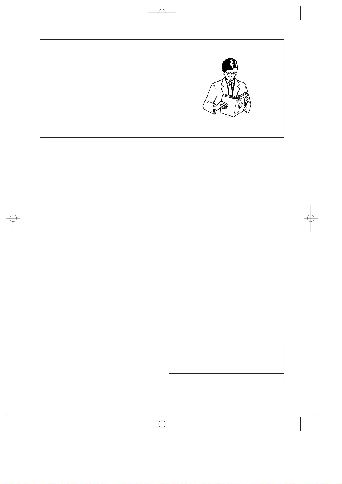
Leggete con attenzione questo
libretto istruzioni prima di
installare e di usare l’apparec-
chio.
Solo così potrete ottenere i
migliori risultati e la massima
sicurezza d’uso. In particolare
prestare attenzione alle avver-
tenze di pagina 10
CONDIZIONI LIMITE
DI FUNZIONAMENTO
Temperatura nella stanza 21 ÷ 32°C
Temperatura esterna 21 ÷ 43°C
PAC40 5-07-2001 12:36 Pagina 2

3
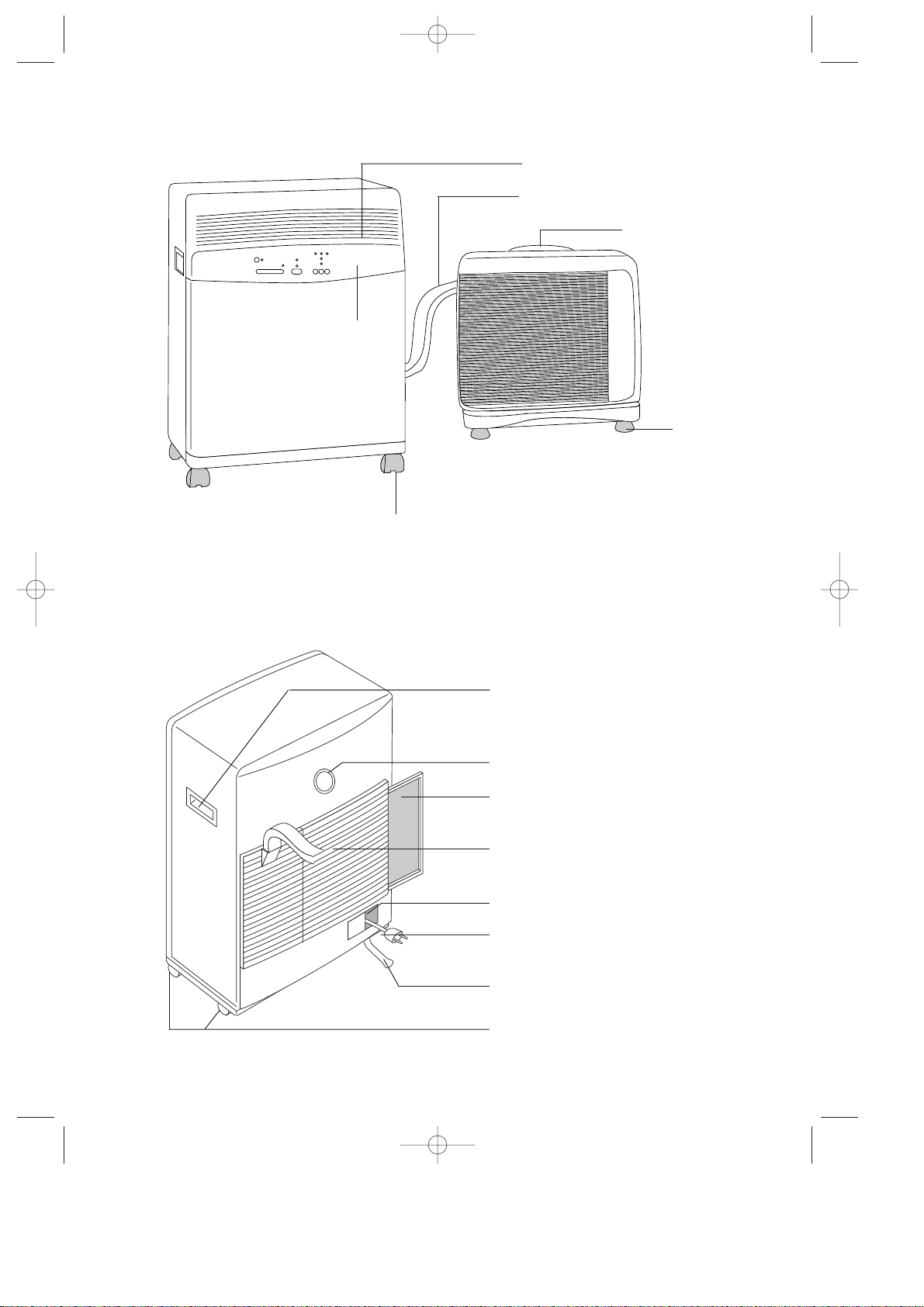
DESCRIZIONE
Griglia mandata aria
Maniglia unità esterna
Ruote
UNITÀ INTERNA
UNITÀ ESTERNA
UNITÀ INTERNA
Maniglia di sollevamento
Filtro estraibile
Griglia di aspirazione aria
Vano cavo alimentazione
Cavo di alimentazione
Tubo di drenaggio condensa
Ruote posteriori
Piedini
Guaina di collegamento
Pannello comandi
Timer
PAC40 5-07-2001 12:36 Pagina 3
4
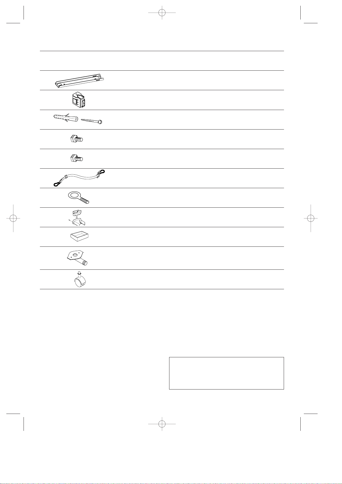
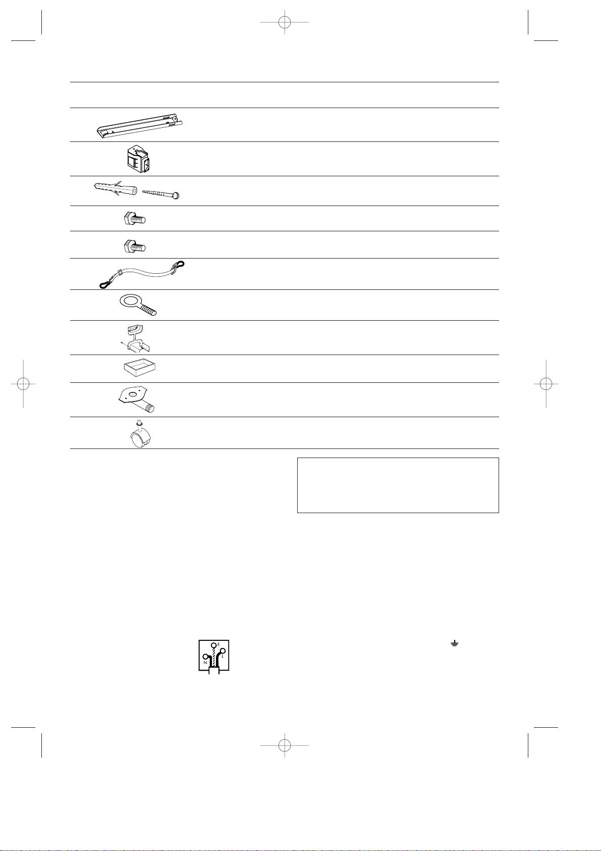
ACCESSORI DI SERIE
ILLUSTRAZIONE DESCRIZIONE N. PEZZI IN DOTAZIONE
Staffa di fissaggio a muro 2
Tasselli ad espansione + viti Ø
6mm
4
Viti M6mm 2
Cinghia con ganci 2
Occhiello per cinghia 2
Cornice per guaina 1
Fermaruote 2
Raccordo drenaggio acqua di
condensa con guarnizione con 2
viti autofilettanti 4.2
1
IMPORTANTE!
La cartolina di registrazione garanzia si trova
nella busta posta sul fianco destro dell’apparec-
chio. Se non avete ancora provveduto, compilate-
la e speditela: solo così fruirete della garanzia. É
nel Vostro interesse!
ASSISTENZA TECNICA
Conservate l’elenco dei Centri Assistenza Tecnica
ed individuate il Centro più vicino a Voi (con il
nostro augurio di non averne mai bisogno).
Su questo apparecchio è installato un sistema
HE (High Efficiency) a basso consumo di ener-
gia che richiede alcuni minuti di attesa, dopo
l’avviamento, per produrre aria fredda.
Ruote per unità esterna e rondelle 4
Viti M4x25 4
Blocchetti supporto per unità ester-
na
2
PAC40 5-07-2001 12:36 Pagina 4
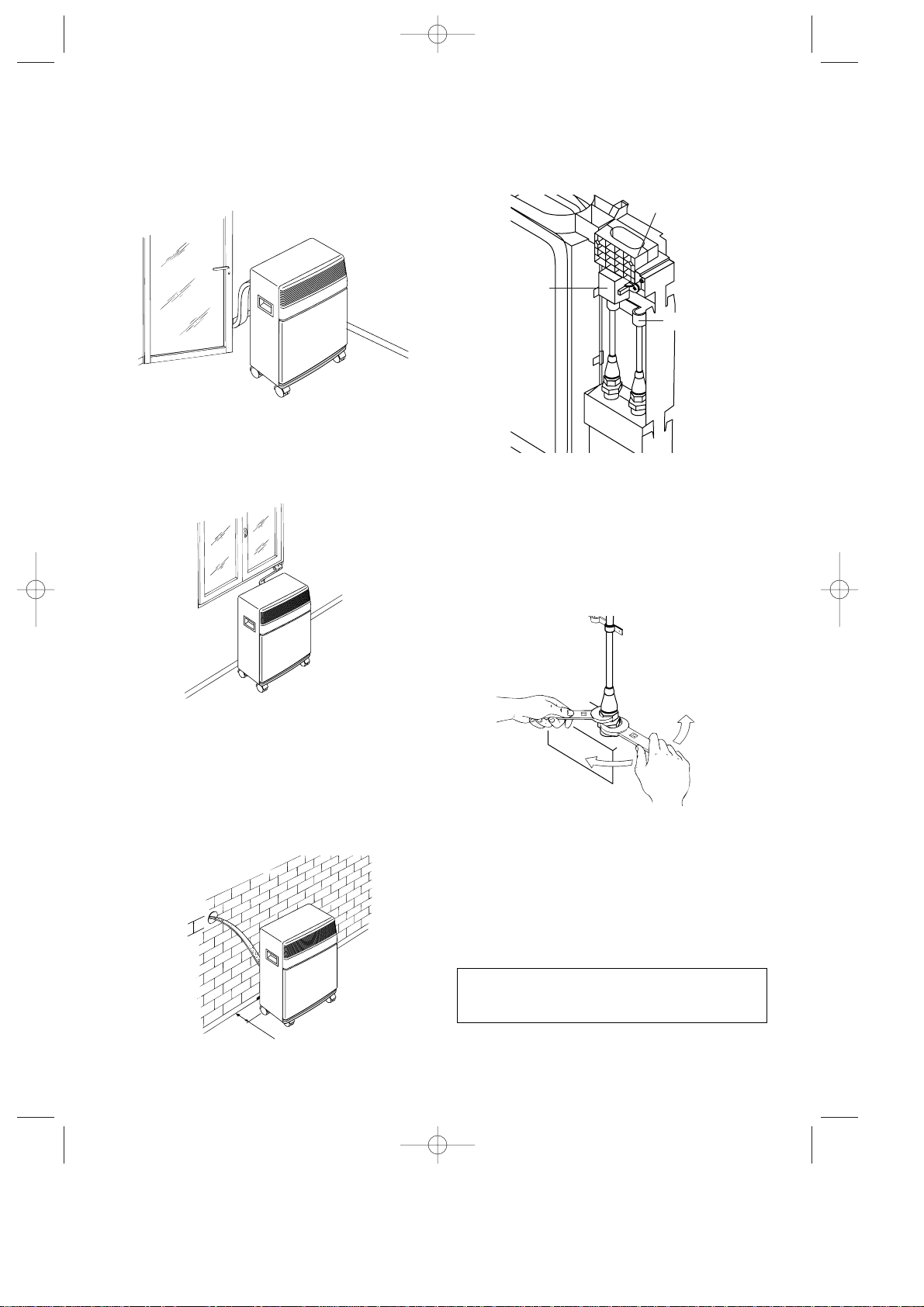
INSTALLAZIONE
La guaina che collega l’unità esterna a quella
interna può passare:
a) Da una fessura di finestra o porta socchiusa.
b) Attraverso una piccola fessura (5,5 cm x 2,5
cm) ricavata nella parte inferiore di una porta o
nel telaio di una finestra, utilizzando la cornice
per guaina in dotazione.
UTILIZZO DEI RACCORDI RAPIDI
In aggiunta ai metodi precedentemente descritti,
la guaina che collega l’unità esterna a quella inter-
na può passare attraverso un foro del diametro di
6 cm. circa, praticato in una parete che comunica
con l’esterno.
In quest’ultimo caso si dovranno staccare i colle-
gamenti dell’unità esterna operando come segue:
1) Togliere la spina dalla presa di corrente.
2) Togliere la maniglia svitando le 2 viti metriche,
quindi sfilare la facciata.
3) Togliere il cavallotto svitando le 2 viti metriche.
4) Togliere il fermaguaina svitando le 2 viti metri-
che.
5) Impiegando una chiave inglese da 24, svitare
il bocchettone girevole del raccordo.
Contemporaneamente, con una chiave da 21,
tenere ferma l’estremità del tubo flessibile.
(Ripetere l’operazione per il secondo bocchet-
tone utilizzando una chiave da 24 e una da
19).
6) Scollegare il tubo di condensa dal portagom-
ma.
7) Svitare le 2 viti autofilettanti della protezione e
disinnestare il blocchetto di connessione elet-
trica.
Evitare le curve troppo secche alla guaina
di collegamento.
5
ø6
cm 30
FERMAGUAINA
PROTEZIONE
BLOCCHETTO DI
CONNESSIONE
ELETTRICA
CAVALLOTTO
PAC40 5-07-2001 12:36 Pagina 5
6
Per ricollegare le estremità della guaina di colle-
gamento, precedentemente staccata, all’unità
interna si dovranno ripetere le operazioni 1, 2, 3,
4, 5, 6 e 7 in senso inverso, osservando le
seguenti precauzioni:
• Prima di far passare la guaina attraverso il foro
del muro si consiglia di proteggere le estremità
filettate dei raccordi rapidi con del nastro iso-
lante o simili.
• Imboccare i 2 raccordi frigoriferi superiori ai 2
inferiori e avvitarli a mano per alcuni giri con-
trollando che siano bene imboccati, e stringe-
re successivamente con le chiavi usate prece-
dentemente.
• Dopo aver collegato i due raccordi frigoriferi,
fissare i cavallotti.
• Verificare la tenuta dei collegamenti frigoriferi
bagnando i giunti con un po’ di acqua sapona-
ta.
Non si deve notare formazione di bolle di
sapone.
Attenzione
É consigliabile far effettuare le operazioni di scol-
legamento e collegamenti dei raccordi rapidi da
personale qualificato.
UNITÀ INTERNA
Installare l’unità interna all’interno del locale da
condizionare. In genere sotto una finestra o in
ogni caso vicino ad una parete perimetrale.
L’unità interna deve essere posizionata “in piano”,
servirsi anche dei fermaruote in dotazione. L’unità
interna non deve avere ostacoli nella zona di aspi-
razione (griglia di aspirazione) e nella zona di
emissione (griglia di uscita).
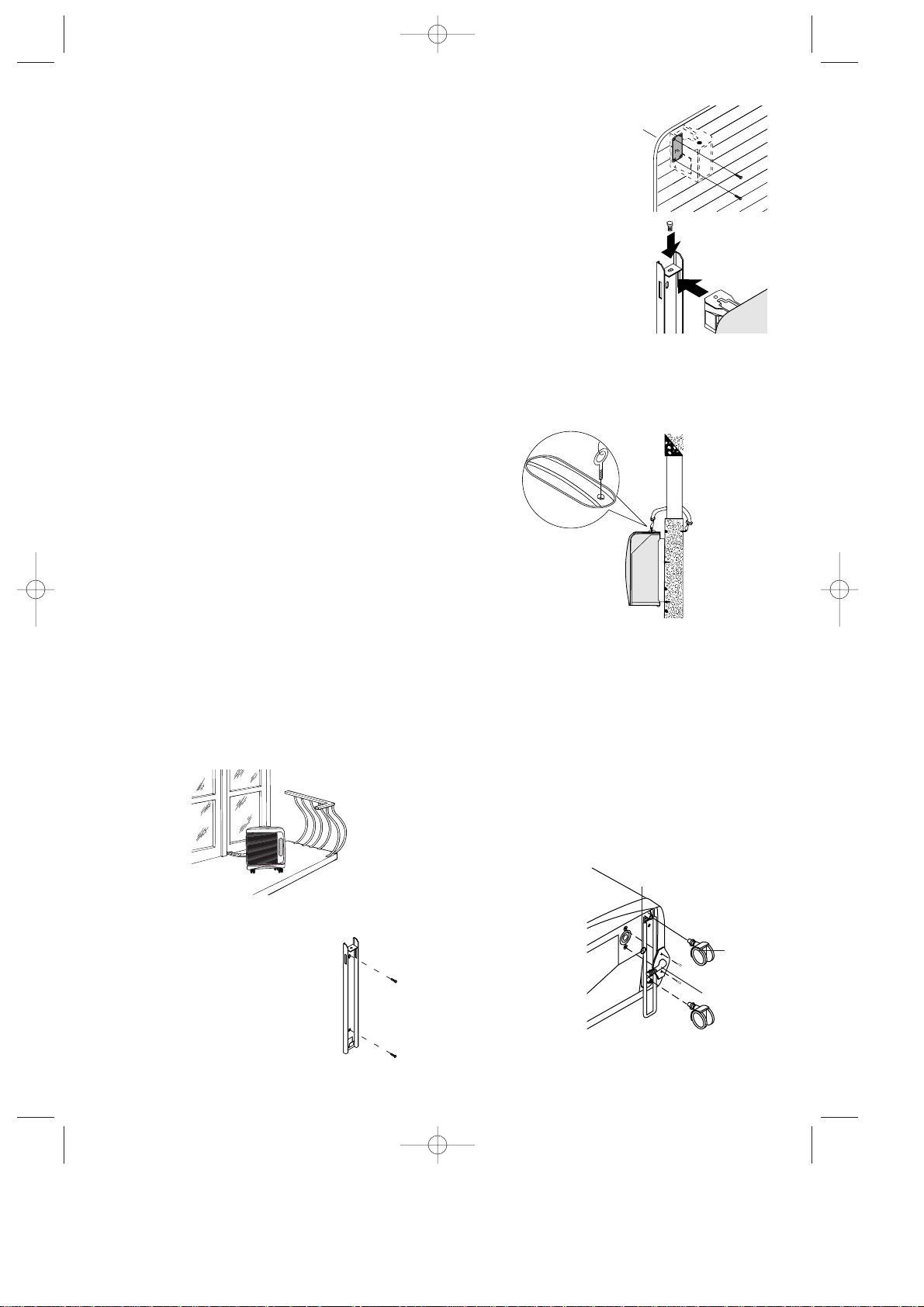
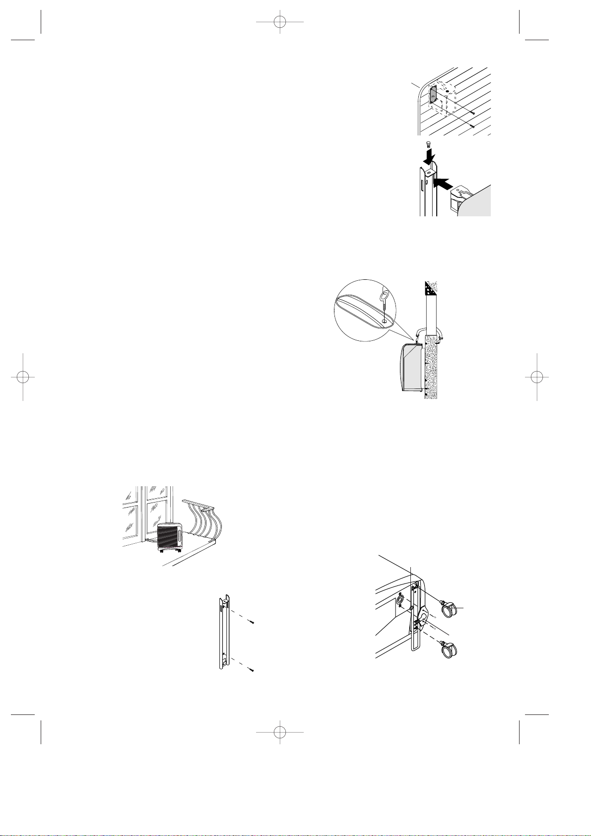
UNITÀ ESTERNA
L’unità esterna può essere appoggiata su una ter-
razza o balcone. In questo caso non è necessario
l’uso delle staffe.
L’unità esterna può essere appesa ad un muro
con le apposite staffe. In questo caso, procedere
come segue:
1) fissare la staffa a muro
facendo attenzione che sia
posizionata come indicato
in figura (per la foratura,
avvalersi della dima ricava-
ta sul coperchio in polistiro-
lo dell’imballo);
2) Per montare i blocchetti
supporto all’unità esterna,
togliere le 2 viti già presen-
ti nelle sedi e avvitare i
blocchetti con le viti M4mm
in dotazione (facendo
attenzione a posizionarli
con il foro per la vite sulla
parte superiore;
3) agganciare quindi l’unità
esterna alle staffe fissan-
dola, poi con la vite
M6mm.
In alternativa per installazioni provvisorie, è possi-
bile sospendere l’unità esterna come indicato in
figura. In questo caso si utilizzeranno le cinghie in
dotazione agganciate agli occhielli; prima di inse-
rire gli occhielli, togliere i tappi in gomma.
L’unità esterna può essere installata sopra o allo
stesso livello dell’unità interna, purché il dislivello
non superi 1,5 m.
L’unità esterna non deve avere ostacoli né sull’a-
spirazione né sulla mandata d’aria.
La distanza tra lo schienale e la parete deve esse-
re di 6 cm. L’acqua di condensa che si forma
durante il funzionamento in condizionamento (fun-
zionamento estivo) viene smaltita per evaporazio-
ne dall’unità esterna.
In casi particolari, se l’umidità è eccessiva, per
smaltire la condensa è necessario utilizzare il rac-
cordo di drenaggio condensa in dotazione, che
deve essere montato
sul basamento del-
l’unità esterna (vedi
figura), dopo aver
tolto il tappo di
gomma.
É consigliabile pro-
teggere l’unità
esterna da pioggia,
neve, da gocciola-
menti dai tetti e dal
sole.
Ruota
Raccordo
Guarnizione
1
2
PAC40 5-07-2001 12:36 Pagina 6
COLLEGAMENTO ELETTRICO
Prima di collegare la spina alla presa di corrente,
bisogna verificare che:
• la tensione di rete sia conforme al valore indi-
cato nelle caratteristiche tecniche;
• la presa e la linea di alimentazione elettrica
siano dimensionate per sopportare il carico
richiesto;
• la presa sia del tipo adatto alla spina, altrimen-
ti far sostituire la presa stessa;
• la presa sia collegata con un efficace impianto
di terra.
La casa costruttrice declina ogni
responsabilità nel caso questa norma
antinfortunistica non fosse rispettata.
• In caso di sostituzione del cavo di alimentazio-
ne usare solo cavi di tipo H05VV-F di sezione
3x1,5 mm
2
.
• Si consiglia l’installazione di un interruttore
bipolare con fusibile di protezione ritardato a
monte della presa di corrente.
Questo apparecchio è conforme alla Norma
EN 55014 sulla soppressione dei radiodi-
sturbi.
• Il cavo di alimentazione deve essere sostitui-
to solo da personale tecnico specializzato.
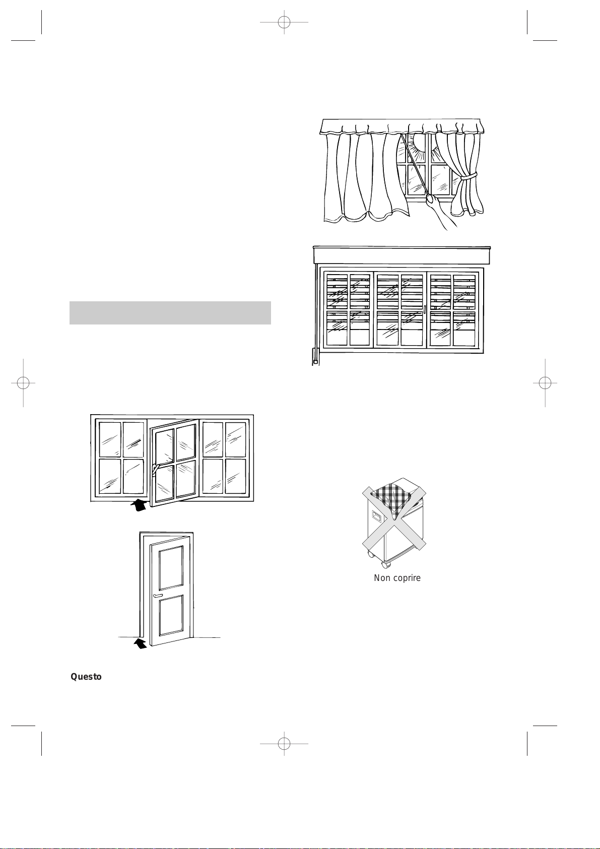
UN’ULTIMA OCCHIATA ALLA STANZA
Ci sono alcune avvertenze da seguire per ottene-
re il massimo rendimento dal climatizzatore:
• chiudere porte e finestre dell’ambiente da condi-
zionare. Unica eccezione nel caso di installazio-
ne attraverso una fessura della finestra, dove è
necessario che quest’ultima rimanga socchiusa.
• Proteggere la stanza dalle esposizioni dirette
del sole, in modo da avere un funzionamento
estremamente economico, tirando le tende e/o
abbassando parzialmente le persiane;
• Non appoggiare oggetti sul climatizzatore;
• Non ostacolare l’aspirazione e la mandata d’aria;
• Assicurarsi che nell’ambiente non vi siano sor-
genti di calore.
N.B: prima di effettuare il collegamento dell’appa-
recchio alla rete elettrica, assicurarsi che tutti
i tasti sul cruscotto siano disinseriti.
COSÌ IL VOSTRO CLIMATIZZATORE È PRONTO
PER FUNZIONARE e pertanto vediamo di familia-
rizzare con i suoi comandi.
Non utilizzare l’apparecchio in ambienti ad alto
tasso di umidità (es. lavanderie).
Non utilizzare l’apparecchio in ambiente esterno
7
Chiudere le finestre
Chiudere le porte
Tirare le tende
Abbassare le persiane
Non coprire
Questo apparecchio è provvisto di un sistema di sicurezza che non permette l’accensione del com-
pressore se non sono trascorsi almeno 3 minuti dall’ultimo spegnimento.
PAC40 5-07-2001 12:36 Pagina 7
8
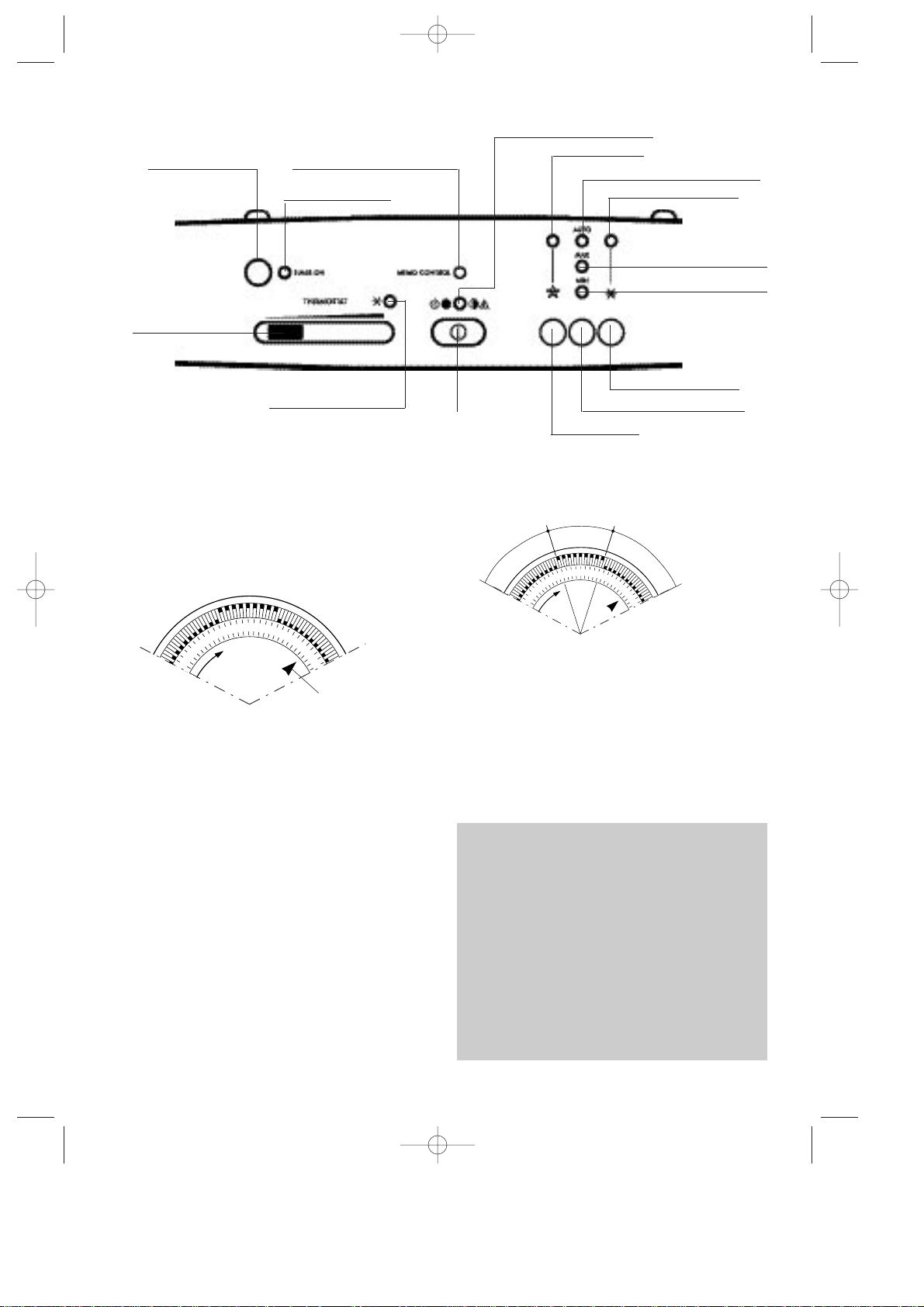
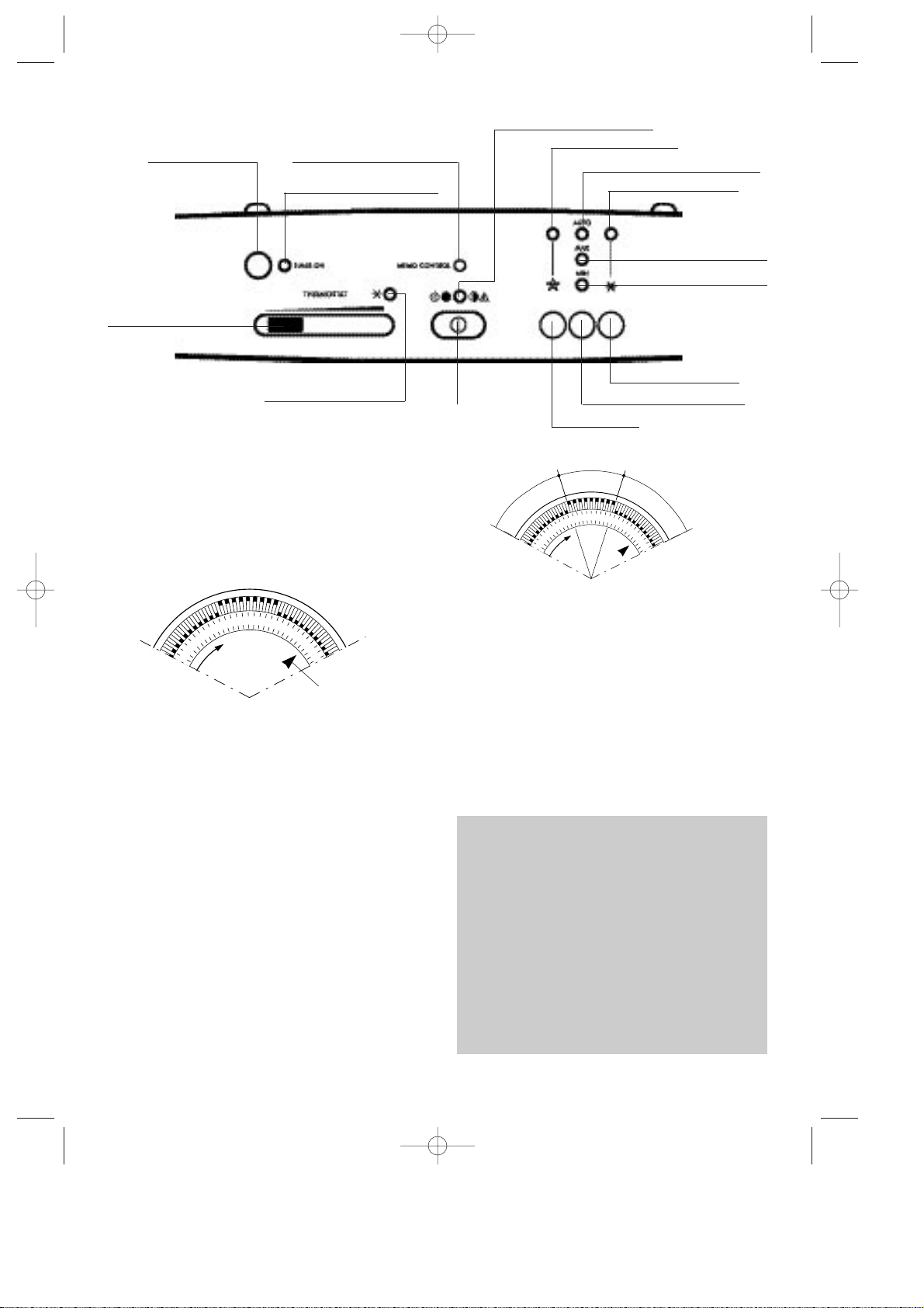
PANNELLO COMANDI
Tasto timer ON/OFF
Spia timer ON/OFF
Spia segnalazione attesa 3
min (lampeggiante) o condi-
zionamento (spia continua)
Se la spia è continua segnala
alimentazione/ se la spia lam-
peggia segnala anomalia
Spia funzionamento automatico
Spia condizionamento
Spia condizionamento
Spia “SLEEP”
TastoON/OFF
Spia ventilazione max.
Spia ventilazione min.
Tasto condizionamento
Tasto velocità del ventilatore
Tasto “SLEEP”
REGOLAZIONE DELL’ORA
Il programmatore/timer, come tutti gli orologi,
deve essere regolato all’ora esatta. Supponendo
che siano le 16:00 ruotare il disco in senso orario
(seguire il senso della freccia) fino a far coincide-
re il numero 16 con l’indice triangolare di riferi-
mento (la freccia indica le ore 16).
N.B.: Non ruotare il quadrante in senso opposto!
Il timer è praticamente un orologio elettrico e fun-
ziona solo finchè la spina è collegata. Ogni qual-
volta la spina viene staccata o manca la corren-
te, il programmatore si ferma e può essere
necessaria una nuova regolazione dell’ora.
Il vostro condizionatore può essere usato “con
timer” o “senza timer”.
FUNZIONAMENTO CON TIMER
1) Scegliere la funzione desiderata seguendo
lo schema della pagina seguente.
2) Premere il tasto TIMER, si accenderà la spia
“TIMER ON”.
3) Assicuratevi che il timer indichi l’ora esatta
(vedi regolazione sull’ora).
4) Impostare i periodi di funzionamento spingen-
do verso l’esterno i dentini compresi nell’inter-
vallo desiderato (ogni dentino sono 15
minuti). L’apparecchio sarà in funzione nell’inter-
vallo delimitato dai dentini verso l’esterno.
Così predisposto l’apparecchio ripeterà ogni gior-
no il programma prefissato.
N.B:Nel caso si desideri escludere il funziona-
mento “con timer”, é sufficiente ripremere il tasto
TIMER (la spia timer ON si spegnerà).
FUNZIONAMENTO SENZA TIMER
1) Ripremere il tasto TIMER ON si spegnerà la
spia timer ON.
2) Scegliere la funzione desiderata seguendo lo
schema alla pagina seguente.
21
20
19
16
indice di
riferimento
21
20
19
16
Funzionamento
S
p
e
n
t
o
A
c
c
e
s
o
S
p
e
n
t
o
Esempio: dalle 19
alle 21
Per ragioni tecniche, la temperatura non è
espressa in gradi ma attraverso una linea che
da sottile diventa sempre più grossa. Si consi-
glia pertanto di iniziare posizionando al massimo
il termostato (linea grossa verde = massimo
freddo). Quando la temperatura ottenuta nel-
l’ambiente sarà quella di confort desiderato,
spostare lentamente il cursore, allontanandovi
dalla posizione di massimo freddo fino a quando
il termostato interverrà spegnendo l’apparec-
chio. Così facendo avrete programmato l’appa-
recchio sull’esatto grado di confort desiderato
che il termostato manterrà automaticamente.
Cursore termostato
PAC40 5-07-2001 12:36 Pagina 8
9
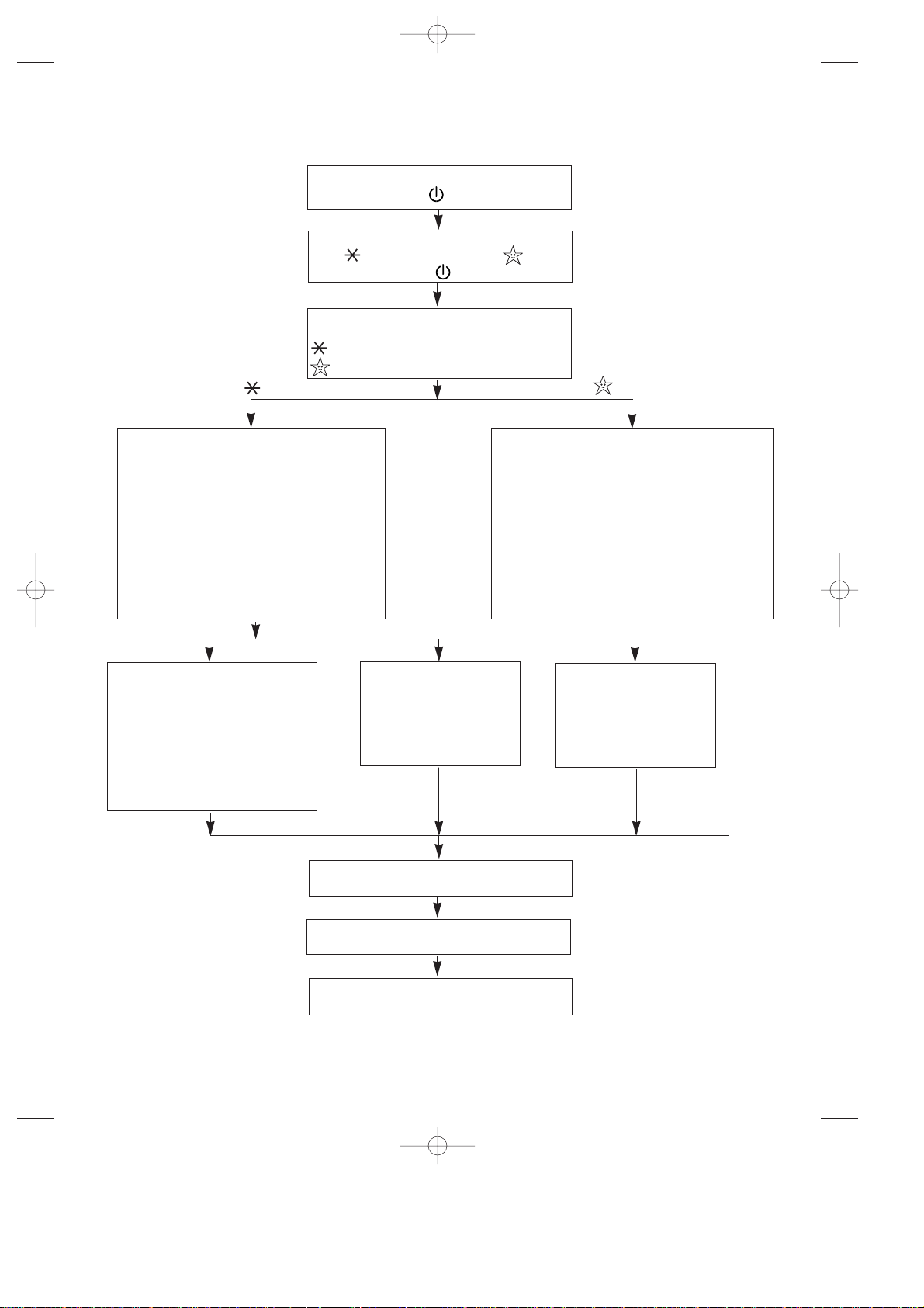
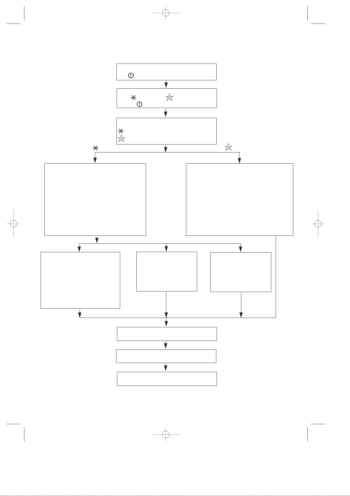
COME METTERE IN FUNZIONE IL CONDIZIONATORE
(vedi pannello di controllo sulla pagina a lato)
Inserire la spina nella presa di corrente.
Si accende la spia .
Premere il tasto ON/OFF. Lampeggiano le
spie (condizionamento) e (sleep)
e si spegne la spia .
Premere il tasto relativo alla funzione desi-
derata:
= Condizionamento
= Sleep
Lampeggiano le spie AUTO, MAX, MIN.
Spostare il cursore del termostato verso la
posizione di MAX freddo e premere il tasto
velocità ventilatori. La sequenza é: MIN,
MAX, AUTO. Alla prima pressione del
tasto, la spia MIN lampeggia per 3 - 4
secondi e si spengono le spie AUTO e
MAX. (Per cambiare potenza ripremere il
tasto scelta potenza.
Rimane accesa la spia SLEEP. Si attiva un
programmpa automatico. L’apparecchio si
attiva alla minima velocità. Raggiunta la tem-
peratura di benessere, l’apparecchio con-
trollerà la temperatura ottimizzando la silen-
ziosità ed evitando l’eccessivo raffredda-
mento. Il PAC 40 riparte solo se la tempera-
tura ambiente è risalita oltre i valori di benes-
sere.
N.B.: E’ preferibile utilizzare la funzione
SLEEP dopo aver condizionato il locale.
Rimane accesa la spia AUTO.
L’apparecchio sceglierà automa-
ticamente la potenza di funziona-
mento a seconda delle condizio-
ni ambientali interne ed esterne
in modo da fornirvi il giusto rap-
porto tra potenza frigorifera e
silenziosità di esercizio.
Rimane accesa la spia
MAX. L’apparecchio fun-
zionerà alla velocità
massima del ventilatore.
Rimane accesa la spia
MIN. L’apparecchio fun-
zionerà alla velocità
minima del ventilatore.
Scegliere il funzionamento “con timer” o
“senza timer” (vedi pagina precedente).
L’apparecchio entra in funzione.
In caso contrario vedi pag. 11.
Per spegnere l’apparecchio
premere il tasto
ON/OFF
Questo apparecchio è provvisto di un sistema di sicurezza che non permette l’accensione del
compressore se non sono trascorsi almeno 3 minuti dall’ultimo spegnimento.
CONDIZIONAMENTO
SLEEP
MIN
MAX
AUTO
PAC40 5-07-2001 12:36 Pagina 9
MANUTENZIONE
Prima di ogni operazione di pulizia o di manuten-
zione, staccare sempre la spina dalla presa di cor-
rente.
Per motivi di sicurezza, non lavare il climatizzato-
re con acqua.
PULIZIA DEL MOBILE
Pulire con un panno che sia soltanto inumidito ed
asciugare con un panno asciutto.
Precauzioni
Mai usare benzina, alcool o solventi per la pulizia.
Mai spruzzare liquido insetticida o simili. La verni-
ce può staccarsi e la plastica si può deformare.
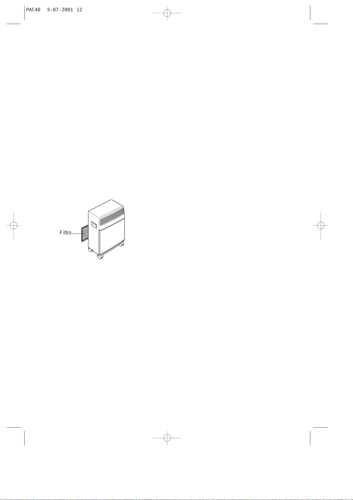
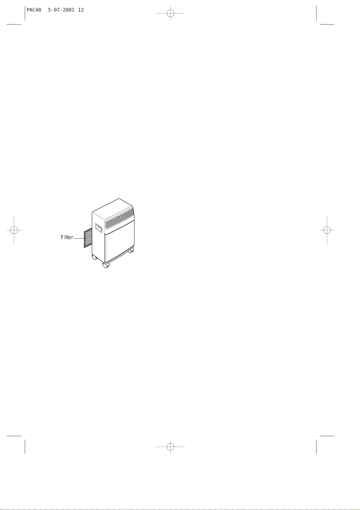
PULIZIA FILTRO ARIA
• Se il filtro dell’aria si sporca, la circolazione
dell’aria viene resa difficile e diminuisce l’effi-
cienza del climatizzatore causando un aumen-
to del consumo di energia elettrica pari al 6%.
Per questo motivo, è buona norma pulire il fil-
tro ogni settimana.
• Per togliere il filtro dell’aria, estrarlo come indi-
cato in figura.
• Per togliere la polvere depositata sul filtro,
usare un aspirapolvere. Se è molto sporco,
immergerlo in acqua tiepida risciacquando più
volte. La temperatura dell’acqua deve essere
inferiore a 40°C. Dopo averlo lavato, lasciare
asciugare il filtro prima di reinserirlo.
VERIFICHE DI INIZIO STAGIONE
Verificare che il cavo di alimentazione e la presa
siano perfettamente integri e assicurarsi che l’im-
pianto di messa a terra sia efficiente. Osservare
scrupolosamente le norme di installazione.
OPERAZIONI DI FINE STAGIONE
Spegnere l’apparecchio.
Fare uscire l’acqua dalla bacinella togliendo il
tappo del tubo di drenaggio
Pulire il filtro e farlo asciugare bene prima di rein-
serirlo.
Coprire l’apparecchio con un sacchetto di plastica
per evitare che si impolveri.
AVVERTENZE
• Questo apparecchio è stato costruito per con-
dizionare, deumidificare e ventilare gli ambien-
ti domestici e non deve essere adoperato per
altri scopi.
• É pericoloso modificare o alterare in qualsiasi
modo le caratteristiche dell’apparecchio.
• Per eventuali riparazioni, rivolgetevi sempre
ed esclusivamente ai Centri di Assistenza
Tecnica autorizzati dalla Casa Costruttrice. Le
riparazioni effettuate da personale incom-
petente possono essere pericolose.
• Questo apparecchio deve essere collegato ad
un’efficace impianto di “terra”. Fate controllare
l’impianto elettrico da un elettricista qualificato.
• Evitare l’utilizzo di prolunghe per il cavo di ali-
mentazione elettrica.
• Prima di ogni operazione di pulizia o di manu-
tenzione, staccare sempre la spina dalla presa
di corrente.
• Non tirare il cavo di alimentazione elettrica per
spostare il prodotto.
• Non installare l’apparecchio in ambienti dove
l’aria può contenere gas, olio, zolfo o in prossi-
mità di fonti di calore.
• Non appoggiare oggetti pesanti o caldi sopra
l’apparecchio.
• Pulire il filtro dell’aria almeno ogni settimana.
• In caso di trasporto, l’apparecchio deve resta-
re in posizione verticale o adagiato su un fian-
co.
• Evitare di utilizzare apparecchi di riscaldamen-
to in prossimità del climatizzatore.
Dopo un trasporto, attendere almeno 1 ora
prima di avviare l’apparecchio.
10
Filtro
PAC40 5-07-2001 12:36 Pagina 10
11
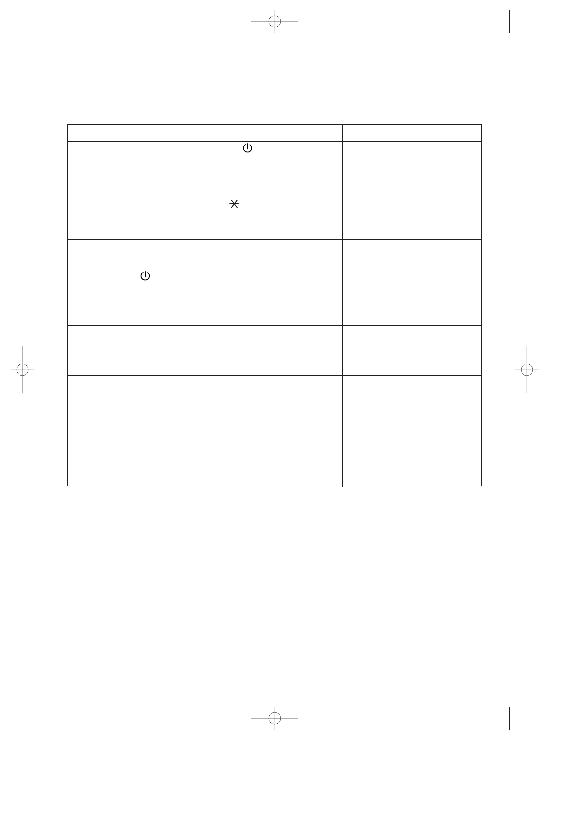
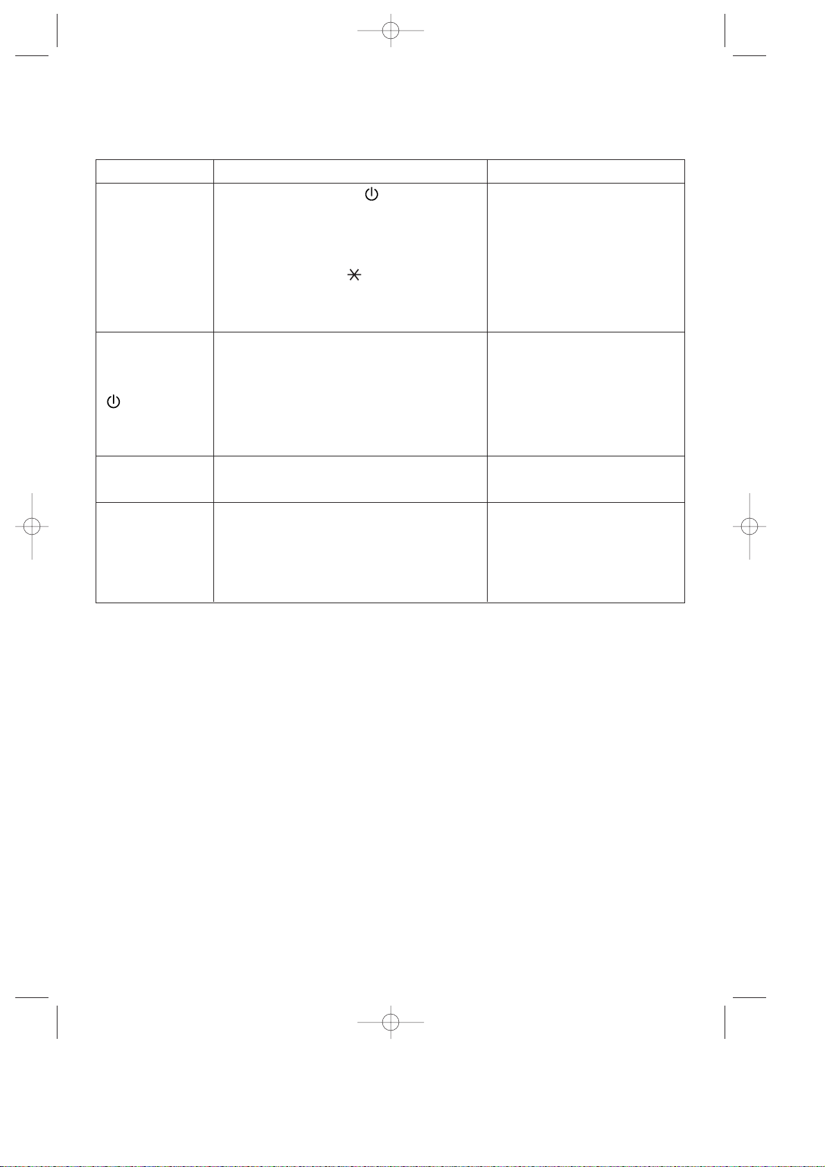
SE QUALCOSA NON FUNZIONA
Se qualcosa non funziona, a volte si tratta di piccoli problemi che voi stessi potrete facilmente risolvere. Verificare
quindi con attenzione queste brevi indicazioni prima di rivolgervi al Centro di Assistenza Tecnica Autorizzato che
opera nella vs. zona.
PROBLEMI CAUSE RIMEDI
Il climatizzatore non
funziona
• attendere
• inserire la spina
• attendere tre minuti
• spostare lentamente il cursore del
termostato verso la posizione
massimo freddo
Il climatizzatore fun-
ziona solo per poco
tempo.
Lampeggia la spia
Il climatizzatore fa
intervenire spesso
l’interruttore genera-
le del contatore
• spegnerlo ed interpellare il Centro
Assistenza
Il climatizzatore fun-
ziona ma non rinfre-
sca la stanza
• finestra aperta
• nella stanza sta funzionando qualche fonte
di calore (bruciatore, lampada, ecc.) oppu
re vi sono molte persone
• termostato regolato troppo alto
• filtro dell’aria intasato
• il condizionatore ha una potenzialità non
adeguata alle condizioni o alle dimensioni
dell’ambiente
• chiudere la finestra
• eliminare la fonte di calore
• abbassare il termostato
• pulire il filtro
ASSISTENZA
Se dopo queste verifiche la disfunzione rimane, rivolgersi al più vicino Centro di Assistenza Tecnica auto-
rizzato specificando il modello di apparecchiatura e il tipo di difetto.
• non è accesa la spia
- manca la corrente
- la spina non è inserita
• lampeggia la spia Memo Control
- non sono passati tre minuti dall’ultimo spegnimen
to
• lampeggia la spia
- nella funzione condizionamento:
la temperatura della stanza è già
inferiore a quella impostata
• è intervenuto il galleggiante di sicurezza perchè
la bacinella all’interno della macchina è troppo
piena
• ci sono delle anomalie nella scheda di controllo
• il ventilatore del condensatore è bloccato
• scaricare l’acqua di condensa toglien-
do il tappo dal tubo di drenaggio.
Se persiste questo inconveniente
chiamare il Centro di Assistenza
• chiamare il Centro di Assistenza
• chiamare il Centro Assistenza
PAC40 5-07-2001 12:36 Pagina 11

12
PAC40 5-07-2001 12:36 Pagina 12

Air-conditioner
PAC 40
Instructions for use
PAC40 5-07-2001 12:36 Pagina 13

14
Carefully read this instructions
booklet before installing or
using this appliance.
Only by doing so will you have
the best results and enjoy the
greatest safety when using the
appliance. Please pay particular
attention to the warnings on
page 22.
OPERATIONAL AIR-
CONDITIONING LIMITS
Room temperature 21 ÷ 32°C
Outside temperature 21 ÷ 43°C
INTRODUCTION
The new PAC 40 is a highly versatile electronical-
ly-controlled air-conditioner: it can be used as a
manual or automatic air-conditioner during the
summer.
This conditioner consists of two units: the internal
unit is designed to operate inside the room to be
conditioned; the external unit is installed in the
open.
The two units are connected by a special hose,
approximately 3 metres in length. This hose con-
tains the freon tubes, the electrical wiring and the
condensation discharge tube.
This appliance also has a SLEEP function. This
function activates a program studied and designed
to increase comfort during sleeping hours. The
program not only ensures perfect silence (from
both the internal and external units) but also con-
trols the temperature of the environment, without
lowering it excessively, to produce the healthiest
conditions.
TECHNICAL FEATURES
Power supply
voltage See the features plate
Maximum absorbed power “
Cooling capacity* “
Number of fan speeds 3
Max. air flow rate 560 m
3
/h
Flexible tube length 3000 mm
Sheathing section 20 x 44 mm
Dimensions: indoor unit
• length 560 mm
• height 735 mm
• depth 355 mm
• weight 44 kg
Dimensions: outdoor unit
• length 570 mm
• height 475 mm
• depth 260 mm
• weight 18 kg
* Standard conditioning:
Inside temperature 27°C
relative humidity: 47%
Outside temperature 35°C
relative humidity: 41%
PAC40 5-07-2001 12:36 Pagina 14
15
DESCRIPTION
Air delivery grille
External unit handle
INTERNAL UNIT
EXTERNAL UNIT
INTERNAL UNIT
Carrying handle
Removable filter
Air intake grille
Power cable compartment
Power cable
Condensation drainage tube
Castors
feet
Connection hose
Control panel
Timer
Castor
PAC40 5-07-2001 12:36 Pagina 15
16
ACCESSORIES
DRAWING DESCRIPTION NO. PIECES PROVIDED
Wall-attachment bracket 2
Anchor screws + screws ø 6 mm
4
Screws M4x25 mm 4
Belt with hooks 2
Screw eye for a belt 2
Sheathing frame 1
Castor stop
2
Drain connection for condensation
with seal and two 4.2 penetrating
screws
1
TECHNICAL SERVICE
Keep the list of Technical Service Centres in a
safe place and check to find the closest Centre
(though we hope you will never have to seek their
help).
This appliance has been fitted with an HE (High
Efficiency) system for low energy consumption,
so after turning the appliance on you may have to
wait a few minutes for cool air to begin circulating.
Castors for the external unit and
washers
4
WARNING - THIS APPLIANCE MUST BE EARTHED
IMPORTANT
The wires in the mains lead are coloured in accordance with the
following code:
Green and yellow: Earth
Blue: Neutral
Brown: Live
As the colours of the wires in the mains lead may not correspond with
the coloured markings identifying the terminals in your plug, proceed
as follows:
The green and yellow wire must be connected to the terminal in the
plug marked with the letter E or the earth symbol or coloured
green or green and yellow.
The blue wire must be connected to the terminal marked with the letter
N or coloured black.
The brown wire must be connected to the terminal marked with the
letter L or coloured red.
ELECTRICAL CONNECTION (U.K. ONLY)
A) If your appliance comes fitted with a plug, it will incorporate a 13
Amp fuse. If it does not fit your socket, the plug should be cut off
from the mains lead, and an appropriate plug fitted, as below.
WARNING: Very carefully dispose of the cut off plug after remo-
ving the fuse: do not insert in a 13 Amp socket elsewhere in the
house as this could cause a shock hazard.
With alternative plugs not incorporating a fuse, the circuit must be
protected by a 15 Amp fuse.
If the plug is a moulded-on type, the fuse cover must be re-fitted
when changing the fuse using a 13 Amp Asta approved fuse to BS
1362. In the event of losing the fuse cover, the plug must NOTbe
used until a replacement fuse cover can be obtained from your
nearest electrical dealer. The colour of the correct replacement
fuse cover is that as marked on the base of the plug.
B) If your appliance is not fitted with a plug, please follow the instruc-
tions provided below:
Support block for external unit
2
Screws M6 mm 2
PAC40 5-07-2001 12:36 Pagina 16

17
INSTALLATION
The sheathing that connects the external to the
internal unit may pass:
a) through a slightly-open window or door;
b) through a small hole (5.5 cm x 2.5 cm) drilled
in the lower part of a door or in a window
frame by using the frame provided.
USE OF RAPID COUPLINGS
In addition to the methods described above, the
sheathing that joins the external to the internal unit
may also be drawn through a hole (about 6 cm. in
diameter) drilled in a wall linked to the outside.
In this case, the hook-ups with the external unit
must be disconnected as follows:
1) Remove the plug from the electric outlet;
2) Remove the handle by loosening the two
screws and then slipping off the facing.
3) Remove the U bolt by loosening the two
screws.
4) Remove the sheath stop by loosening the two
screws.
5) Using a 24-version wrench, unscrew the union
on the coupling. At the same time, hold the end
of the flexible tube tight by using a 21-version
wrench. Repeat this operation for the second
union using a 24- and a 19-version wrench.
6) Disconnect the condensation tube from the
rubber holder.
7) Loosen the shield’s two self-threading screws
and disconnect the electric hook-up unit.
The path of the connecting sheath should
be as straight as possible, without sharp
curves or kinks.
ø6
cm 30
SHEATH STOP
ELECTRIC
HOOK-UP
SHIELD
U BOLT
PAC40 5-07-2001 12:36 Pagina 17
18
To re-connect the detached ends of the sheath to
the internal unit, you must repeat operations 1
through 7 in reverse order, being careful to obser-
ve the following precautions:
• Before drawing the sheath through the hole in
the wall, you should wrap the threaded ends of
the speedy couplings with friction tape or the
like as a protective measure.
• Fit the upper two cooling junctures into the two
lower ones and hand-screw them several turns
while checking to be certain they are well-fit-
ted, and then tighten them with the wrenches
used earlier.
• After having hooked up the two cooling junctu-
res, tighten the U bolts.
• Check the grip on the cooling junctures by wet-
ting the joints with a little soapy water.
No bubbles should appear.
Caution:
We recommend that the disconnecting and con-
necting of the rapid couplings be carried out only
by qualified technicians.
INTERNAL UNIT
Install the internal unit inside the room to be air-
conditioned. This is usually done under a window
or at least close to an outside wall.
The internal unit must be placed “on the level”,
with the help of the castor-stops provided. No
obstacles should block this unit’s in-take (suction
grille) or out-take (outlet grille) areas.
EXTERNAL UNIT
The external unit may be placed on a terrace or
balcony, in which case the brackets need not be
used.
The external unit can be attached to a wall with the
accessories included as follows:
1) Attach the bracket to the
wall while taking care to
place it as indicated in the
drawing. Use the included
template located on the
plastic cover in order to drill
the holes.
2) T o fix the support blocks to
the external unit remove
the two screws already
inserted in the holes. Than
screw the support blocks
with the included M4mm
screws while taking care
to place them so that the
hole for the screws is on
the upper side.
3) Attach the external unit to
the bracket by means of
the M6mm screws.
For temporary installation it is possible to hang the
external unit as illustrated in the drawing. In this
case, use the included straps by attaching them to
the eye hooks. Before inserting the eye hooks
remove the rubber plugs.
The external unit may be installed above or at the
same height as the internal unit, on the condition
that the difference is no more than 1.5 m.
The suction and air-delivery portions of external
unit must not be blocked by obstacles of any natu-
re.
The distance between the back of the appliance
and the wall must be six (6) cm.
The condensation which forms while this applian-
ce is running (summertime operations) is disposed
of by evaporation from the external unit.
If the humidity is too high (in special cases), you
must use the drainage coupling provided to get rid
of condensation. This device must be mounted on
the bottom of the
external unit (see
drawing) after the
rubber plug has
been removed.
We strongly recom-
mend that you pro-
tect the external unit
from rain, snow,
direct sunlight and
water dripping from
the roof.
Castor
Drainage
Coupling
Gasket
1
2
PAC40 5-07-2001 12:36 Pagina 18

19
ELECTRICAL CONNECTIONS
Before putting the plug in an electrical outlet, you
must check to be certain that:
• the voltage is the same as that indicated in the
technical features;
• the socket and the mains circuit are of suffi-
cient size to handle the power required;
• the socket is suitable for the plug, because
otherwise the socket must be replaced;
• the socket is connected to a good earthing
system, because t
he manufacturer shall in
no way be held responsible for situations
resulting from the failure to comply with
this accident-preventing measure.
• when replacing the feed cable, use only cables
of the HO5VV-F type having a section measu-
ring 3 x 1.5 mm
3
• We recommend the installation (just past the
electrical outlet) of a bipolar switch with a
delayed protection fuse.
This appliance complies with the EN 55014
norms on the suppression of radio interference.
• Replacement of the power cable must be
carried out by qualified personnel.
A LAST LOOK AT THE ROOM
There are several precautions you should keep in
mind so as to get the best use out of your air-con-
ditioner:
• Close the doors and windows in the room to be
air-conditioned (except for temporary installa-
tion, in which case a window must be left par-
tially open).
• In order to insure low-cost operations, protect
the room from direct sunlight by drawing the
curtains and/or by partially lowering or closing
the shutters or blinds
• Do not place objects atop the air-conditioner.
• Do not block the suction and air delivery areas.
• Make certain there are no heating sources in
the room.
N.B: Before connecting this appliance to the elec-
trical circuit, make certain that all the buttons
on the control panel are switched off.
IN THIS WAY, YOUR AIR-CONDITIONER IS
READY TO WORK, so now let’s familiarise our-
selves with its controls.
Do not install the heater in humid environments
(es. laundry).
Do not use outdoors.
Close the windows
Close the doors
Draw the curtains
Lower (or partially close) the shutters
Do not cover
This appliance is equipped with a safety system which prevents the compressor from turning on
until at least three (3) minutes have elapsed since the appliance was last turned off.
PAC40 5-07-2001 12:36 Pagina 19
20
CONTROL PANEL
ON/OFF Timer key
Timer signal lamp ON/OFF
Signal lamp indicating 3 min.
wait (flashing) or working
appliance (on continuously)
Signal lamp mains (conti-
nuous light) or malfunction
(flashing light)
Automatic function signal lamp
Air-cooling signal lamp
Air-cooling signal lamp
“SLEEP” signal lamp
ON/OFF key
max. speed signal lamp
min. speed signal lamp
Air-cooling key
Fan speed key
“SLEEP” key
SETTING THE TIMER
Ther programmer/timer, like all clocks, must be
set to the exact time. If for example it is 4.00 p.m.
(16.00), turn the dial in a clockwise direction (fol-
lowing the direction of the arrow) until the number
16 is lined up with the tringular pointer (the arrows
indicates 4:00 p.m. approximately).
N.B.: Never turn the dial in anti-clockwise direc-
tion!
The timer is in effect, an electric clock and works
only if the plug is connected to the power supply.
Whenever the plug is disconnected or there is a
power failure, the programmer stops (the clock is
then "slow" and must be re-set.
Select operation "with timer" or "without timer".
OPERATION WITH TIMER
1) Select the desired function as shown in the
chart overleaf.
2) Press the TIMER key, the "TIMER ON" signal
lamp will come ON.
3) Make sure that the timer indicates the correct
time (see instructions on setting).
4) Set the operating times by pushing out the
notches on the dial corresponding to the
period required (each notch represent 15
mins).
The air-conditioner will now switch on each day at
the selected times.
N.B.: If you wish to override the programmed
operating times, simply press the ON/OFF timer
key (the timer signal lamp ON will go out).
OPERATIONG WITHOUT TIMER
1) Press the TIMER ON key again, the TIMER
ON signal lamp will go out.
2) Select the desired function as shown in the
chart on page. 21.
21
20
19
16
indice di
riferimento
21
20
19
16
Function
O
F
F
O
N
O
F
F
Example: from 7 p.m. to 9 p.m.
For technical reasons, the temperature is not
expressed in degrees but by a line increasing
in thickness. We therefore recommend that
when starting up the appliance, the thermostat
be turned to maximum (thick green line = maxi-
mum cold). When the desired temperature has
been reached move the thermostat slider
slowly away from the maximum cold position
until the appliance is switched off by operation
of the thermostat. In this way the appliance has
been programmed with the exact temperature
degree required, which is then maintained
automatically by the thermostat.
Thermostat slider
PAC40 5-07-2001 12:36 Pagina 20
21
HOW TO OPERATE THE AIR-CONDITIONER
(REFER TO THE CONTROL PANEL ON THE OPPOSITE PAGE)
Plug the appliance into the power socket.
The pilot lamp lights.
Press the ON/OFF key. The conditioning
and sleep pilot lamps flash
and the pilot lamp switches off.
Press the button for the desired function:
= Air-conditioning
= Sleep
The signal lamps AUTO, MAX, MIN are
flashing. Move the slider on the thermostat
towards MAX cold and press the fan
speed key. The correct sequence is MIN,
MAX, AUTO. When the key is pressed
the first time, the MIN lamp will flash for
3 - 4 seconds and the AUTO and MAX
lamps will go out (to modify the power,
press the relevant key).
The SLEEP warning lamp remains on. An
automatic program is enabled. The applian-
ce is activated at minimum speed. Once the
ideal temperature has been reached, the
appliance controls the temperature in perfect
silence, ensuring that it does not drop
excessively. The PAC 40 will only restart if the
temperature exceeds levels considered
healthy.
N.B: The room should always be air-condi-
tioned before the SLEEP function is used.
The AUTO signal lamp comes
on. The appliance will automati-
cally select the fan speed accor-
ding to the internal and external
ambient conditions. In this way,
the machine will provide the cor-
rect cooling power and operate
with the minimum noise.
The MAX signal lamp
comes on. The applian-
ce will function at the
maximum fan speed.
The MIN signal almp
comes on. The applian-
ce will function at the
minimum fan speed.
Select the desired operating mode “with
timer” or “without timer” (see previous page).
The appliance comes on.
If not, refer to page 23.
To switch off the appliance,
press the
ON/OFF push-button.
This appliance is fitted with a special safety circuit. When the compressor switches off, this cir-
cuit prevents it from switching on again for at least 3 minutes.
AIR-CONDITIONING
SLEEP
MIN
MAX
AUTO
PAC40 5-07-2001 12:36 Pagina 21
22
MAINTENANCE
Always pull the plug from the electrical outlet befo-
re beginning any cleaning or maintenance opera-
tions.
For safety reasons, never wash the air-conditioner
with water.
CLEANING THE UNIT
Clean your air-conditioner with a damp cloth and
then wipe it with a dry cloth.
Precautions:
Never use gasoline, alcohol or solvents to clean
this appliance. Never spray it with insecticide or
similar liquids, because the paint might then peel
away and the plastic portions might lose their true
shape.
CLEANING THE AIR FILTER
• If the air filter gets dirty, it will be dif ficult for the
air to circulate and the air-conditioner will lose
much of its efficiency, thus leading to about an
8% increase in electrical consumption. For this
reason, it is a good idea to clean the filter
• Remove the air filter as shown below.
• Use a vacuum cleaner to remove the dust on
the filter. If the filter is very dirty, dip it in warm
water (of less than 40° C.) and rinse it several
times. After having washed the filter, let it dry
completely before putting it back in place.
CHECKS TO MAKE AT A SEASON’S
BEGINNING
Check to make certain that the power cable and
the electrical outlet are in perfect condition and
that there is a suitable earthing system.
Give strict observance to all installation norms.
WORK TO BE DONE AT A SEASON’S END
Turn off the air-conditioner.
Clean the filter and dry it before putting it back in
place.
Cover the air-conditioner with a plastic bag to
keep the appliance from getting dusty.
Remove the batteries from the remote control
device.
IMPORT ANT ADVICE
• This appliance has been built to air-condition,
dehumidify and ventilate rooms in the home
and must not be used for other purposes.
• Changing or altering the features of this featu-
re in any way is dangerous.
• If repairs are needed, always contact only a
Technical Assistance Centre authorised by the
manufacturer. Repairs by unauthorised per-
sonnel may be inherently dangerous.
• This appliance must be connected to an effi-
cient “earthing” system. Have your electrical
system checked out by a qualified electrician.
• Avoid using extension cords for the electric
feed cable.
• Before any cleaning or maintenance, always
pull the plug from its electric outlet.
• Never pull on the feed cable to move this
equipment.
• Do not install this appliance in rooms where
the air may contain gas, oil or sulphur or in the
close proximity of a heat source.
• Never place heavy or hot objects on this air-
conditioner.
• Clean the air filter at least once a week.
• When being moved, this appliance must be
kept in an upright position or placed carefully
on one side.
• Do not make use of heating equipment in the
close proximity of this air-conditioner.
After having moved this appliance, wait for at
least one (1) hour before turning it on again.
Filter
PAC40 5-07-2001 12:36 Pagina 22
23
IF SOMETHING GOES WRONG
Most malfunctions are caused by a very minor and easily solved problem. So carefully check this list befo-
re contacting the Authorised Technical Service Centre in your area.
PROBLEMS CAUSES REMEDIES
The air-conditioner
does not function
• if the pilot lamp is not lit
- power failure
- the appliance is not plugged in
• if the Memo Control pilot lamp is flashing
- less than 3 minutes have passed since
the appliance was last switched off
• if the pilot lamp is lit
- in conditioning mode: the temperature in the
room is already lower than the selected tempe-
rature
• wait until the power supply is restored
• insert the plug
• wait three minutes
• slide thermostat slider slowly to
the maximum cooling position
The air-conditioner
functions for a brief
period only. The
pilot lamp flashes
• the safety float has switched the appliance off
because the condensation tray inside the
appliance is full
• the control circuit board is faulty
• the condenser fas has jammed
• remove the plug from the drai-
nage tube and drain the con-
densation from the tray.
If this fault persists, contact
your nearest Service Centre.
• contact your nearest Service
Centre
• contact your nearest Service
Centre
The appliance swit-
ches on and off
constantly
• switch the appliance off and
contact your nearest Service
Centre
The air-conditioner
functions but the
room is not cooled
• window open
• source of heat in the room (heater, lamp, etc.) or
the room is very crowded
• the thermostat is set too high
• the air filter is dirty
• the air-conditioner is not powerful enough for the
size or the conditions of the room
• close the window
• remove source of heat
• lower the thermostat setting
• clean the filter
SERVICE
If the problem persists after these checks have been made, contact your nearest authorised Technical
Service Centre. Specify the model you own and the type of defect encountered.
PAC40 5-07-2001 12:36 Pagina 23

24
PAC40 5-07-2001 12:36 Pagina 24
Climatiseur d’air
PAC 40
Mode d’emploi
PAC40 5-07-2001 12:36 Pagina 25
 Loading...