


 Loading...
Dell DSS 7000/DSS 7500 Owner's Manual
Regulatory Model: B14S
Regulatory Type: B14S001

Notes, Cautions and Warnings
 NOTE: A NOTE indicates important information that helps you make better use of your computer.
CAUTION: A CAUTION indicates either potential damage to hardware or loss of data and tells you how to avoid the problem.
 WARNING: A WARNING indicates a potential for property damage, personal injury, or death.
Copyright © 2016 Dell Inc. All rights reserved. This product is protected by U.S. and international copyright and intellectual property laws. Dell™ and the Dell logo are trademarks of Dell Inc. in the United States and/or other jurisdictions. All other marks and names mentioned herein may be trademarks of their respective companies.
2016 - 9
Rev. A02
Contents |
|
1 About your system............................................................................................... |
8 |
Front-panel features and indicators............................................................................................. |
8 |
Back-panel features and indicators............................................................................................ |
10 |
HDD indicator codes...................................................................................................................... |
12 |
NIC indicator codes........................................................................................................................ |
13 |
Indicator codes for the redundant PSU..................................................................................... |
14 |
Documentation matrix................................................................................................................... |
15 |
2 Performing initial system configuration....................................................... |
16 |
Setting up your system.................................................................................................................. |
16 |
Installing the rack and the server................................................................................................ |
16 |
Installing the rails..................................................................................................................... |
16 |
Installing the cable management arm (CMA).................................................................... |
18 |
Setting up and configuring the iDRAC IP address................................................................... |
20 |
Configuring the iDRAC settings for the dedicated management port card....................... |
21 |
Logging in to iDRAC....................................................................................................................... |
21 |
Installing the OS.............................................................................................................................. |
22 |
Managing your system remotely................................................................................................ |
22 |
Downloading and installing drivers and firmware................................................................... |
22 |
Installing the driver for the LSI 9311 card on a Ubuntu1404 system............................ |
23 |
3 Pre-operating system management applications....................................... |
24 |
Navigation keys............................................................................................................................... |
24 |
About System Setup....................................................................................................................... |
24 |
Entering System Setup........................................................................................................... |
25 |
System Setup Main Menu...................................................................................................... |
25 |
System BIOS page................................................................................................................... |
25 |
System Information page...................................................................................................... |
26 |
Memory Settings page........................................................................................................... |
26 |
Processor Settings page......................................................................................................... |
27 |
SATA Settings page.................................................................................................................. |
29 |
Boot Settings page.................................................................................................................. |
30 |
Integrated Devices page details............................................................................................ |
31 |
Serial Communication page................................................................................................. |
32 |
System Profile Settings page................................................................................................. |
33 |
System Security Settings page.............................................................................................. |
34 |
Secure Boot Custom Policy Settings page........................................................................ |
35 |
Miscellaneous Settings page................................................................................................. |
36 |
About Boot Manager..................................................................................................................... |
36 |
Entering Boot Manager.......................................................................................................... |
36 |
Boot Manager main menu..................................................................................................... |
37 |
About Dell Lifecycle Controller................................................................................................... |
37 |
Changing the boot order.............................................................................................................. |
37 |
Choosing the system boot mode............................................................................................... |
37 |
Assigning a system and setup password................................................................................... |
38 |
Using your system password to secure your system............................................................. |
39 |
Deleting or changing an existing system and/or setup password....................................... |
39 |
Operating with a setup password enabled............................................................................... |
40 |
Embedded system management................................................................................................ |
40 |
iDRAC Settings utility..................................................................................................................... |
40 |
Entering the iDRAC Settings utility...................................................................................... |
40 |
Changing the Thermal Settings............................................................................................ |
40 |
4 Installing and removing system components.............................................. |
42 |
Safety instructions.......................................................................................................................... |
42 |
Before working inside your system............................................................................................ |
42 |
After working inside your system................................................................................................ |
42 |
Recommended tools..................................................................................................................... |
43 |
System cover................................................................................................................................... |
43 |
Removing the system cover.................................................................................................. |
43 |
Installing the system cover.................................................................................................... |
44 |
Server sleds...................................................................................................................................... |
44 |
Removing the server sled...................................................................................................... |
44 |
Installing the server sled......................................................................................................... |
45 |
Expansion cards and expansion-card riser module................................................................ |
46 |
Expansion card installation guidelines................................................................................ |
46 |
Removing the expansion-card riser module..................................................................... |
47 |
Installing the expansion-card riser module....................................................................... |
48 |
Removing an expansion card............................................................................................... |
48 |
Installing an expansion card.................................................................................................. |
49 |
Installing an optional card..................................................................................................... |
50 |
Installing the supercapacitor................................................................................................. |
52 |
Removing a riser card............................................................................................................. |
54 |
Installing a riser card............................................................................................................... |
55 |
Cooling shroud............................................................................................................................... |
56 |
Removing the cooling shroud.............................................................................................. |
56 |
Installing the cooling shroud................................................................................................ |
57 |
System memory.............................................................................................................................. |
57 |
General memory module installation guidelines............................................................. |
58 |
Mode-specific guidelines...................................................................................................... |
59 |
Sample memory configurations........................................................................................... |
60 |
Removing a memory module............................................................................................... |
61 |
Installing a memory module................................................................................................. |
62 |
Heat sinks and processors............................................................................................................ |
64 |
Removing a processor........................................................................................................... |
64 |
Installing a processor.............................................................................................................. |
67 |
Hard disk drives............................................................................................................................... |
70 |
Removing a 3.5-inch HDD blank......................................................................................... |
70 |
Installing a 3.5-inch HDD blank............................................................................................ |
71 |
Removing a 3.5-inch hot-swap HDD.................................................................................. |
71 |
Installing a 3.5-inch hot-swap HDD.................................................................................... |
72 |
Removing a 3.5-inch HDD from an HDD carrier.............................................................. |
73 |
Installing a 3.5-inch HDD into an HDD carrier.................................................................. |
74 |
Removing a 2.5-inch hot-swap HDD................................................................................. |
74 |
Installing a 2.5-inch hot-swap HDD.................................................................................... |
75 |
Installing a 2.5-inch SSD into a 3.5-inch HDD adapter................................................... |
76 |
Removing a 2.5-inch SSD from a 3.5-inch HDD adapter............................................... |
76 |
Installing an HDD adapter into an HDD carrier................................................................. |
77 |
Removing an HDD adapter from an HDD carrier............................................................. |
78 |
Removing a 2.5-inch SSD from an HDD carrier............................................................... |
78 |
Installing an HDD into an HDD carrier................................................................................ |
78 |
System fans...................................................................................................................................... |
79 |
Removing a system fan.......................................................................................................... |
79 |
Installing a system fan............................................................................................................ |
80 |
Removing the fan cage.......................................................................................................... |
80 |
Installing the fan cage............................................................................................................ |
81 |
PSUs.................................................................................................................................................. |
82 |
Removing a redundant PSU.................................................................................................. |
82 |
Installing a redundant PSU.................................................................................................... |
83 |
System battery................................................................................................................................ |
84 |
Replacing the system battery................................................................................................ |
84 |
Interposer board............................................................................................................................. |
85 |
Removing the interposer board........................................................................................... |
85 |
Installing the interposer board............................................................................................. |
86 |
Expander board.............................................................................................................................. |
87 |
Removing the expander board............................................................................................. |
87 |
Installing the expander board............................................................................................... |
89 |
Paddle board................................................................................................................................... |
89 |
Removing the paddle board.................................................................................................. |
89 |
Installing the paddle board.................................................................................................... |
90 |
HDD cage and backplane............................................................................................................. |
90 |
|
Removing the HDD cage and backplane........................................................................... |
90 |
|
Installing the HDD cage and backplane............................................................................. |
93 |
|
System board.................................................................................................................................. |
95 |
|
Removing the system board................................................................................................. |
95 |
|
Installing the system board................................................................................................... |
97 |
|
Trusted Platform Module....................................................................................................... |
99 |
5 |
Troubleshooting your system........................................................................ |
101 |
|
Safety first—for you and your system...................................................................................... |
101 |
|
Troubleshooting system startup failure................................................................................... |
101 |
|
Troubleshooting external connections.................................................................................... |
101 |
|
Troubleshooting the video subsystem..................................................................................... |
101 |
|
Troubleshooting a USB device.................................................................................................. |
101 |
|
Troubleshooting a serial I/O device......................................................................................... |
102 |
|
Troubleshooting a NIC................................................................................................................ |
102 |
|
Troubleshooting a wet system.................................................................................................. |
103 |
|
Troubleshooting a damaged system........................................................................................ |
104 |
|
Troubleshooting the system battery........................................................................................ |
105 |
|
Troubleshooting PSUs................................................................................................................. |
105 |
|
Power source issues............................................................................................................. |
105 |
|
PSU issues............................................................................................................................... |
106 |
|
Troubleshooting cooling issues................................................................................................ |
106 |
|
Troubleshooting system fans..................................................................................................... |
107 |
|
Troubleshooting system memory............................................................................................. |
107 |
|
Troubleshooting HDDs................................................................................................................ |
108 |
|
Troubleshooting expansion cards............................................................................................. |
109 |
|
Troubleshooting processors...................................................................................................... |
110 |
|
Troubleshooting server sleds..................................................................................................... |
110 |
|
System messages......................................................................................................................... |
110 |
|
Warning messages................................................................................................................ |
110 |
|
Diagnostic messages............................................................................................................. |
111 |
6 |
Using system diagnostics............................................................................... |
112 |
|
Dell Embedded System Diagnostics......................................................................................... |
112 |
|
When to use the Embedded System Diagnostics........................................................... |
112 |
|
Running the Embedded System Diagnostics from Boot Manager.............................. |
112 |
|
Running the Embedded System Diagnostics from the Dell Lifecycle Controller..... |
112 |
|
System diagnostic controls.................................................................................................. |
113 |
7 |
Jumpers and connectors............................................................................... |
114 |
|
System board jumper settings.................................................................................................... |
114 |
|
System board connectors........................................................................................................... |
115 |
|
Disabling a forgotten password................................................................................................. |
117 |
8 |
Technical specifications................................................................................. |
118 |
9 |
Getting help...................................................................................................... |
124 |
|
Contacting Dell............................................................................................................................. |
124 |
|
Locating your system Service Tag............................................................................................ |
124 |
1
About your system
The Dell 4U rack server contains the DSS 7000 chassis and up to two DSS 7500 server sleds. Each server sled supports up to two processors based on the Intel Xeon EP E5-2600 v3 family and EP E5-2600 v4 family, up to 12 DIMMs, and up to two boot solid state drives (SSDs). The chassis supports up to 90 hard disk drives (HDDs)/SSDs.
The server systems are available in the following configurations:
System |
Configuration |
|
|
Single-node systems with one |
Up to 90 3.5-inch hot-swappable Serial Attached SCSI (SAS) HDDs, |
server sled |
SATA HDDs, or SATA SSDs, or |
|
Up to 16 hot-swappable SAS SSDs |
|
Up to two 2.5-inch hot-swappable boot SATA SSDs |
Dual-node systems with two |
Up to 90 3.5-inch hot-swappable Serial Attached SCSI (SAS) HDDs, |
server sleds |
SATA HDDs, or SATA SSDs, or |
|
Up to 12 hot-swappable SAS SSDs |
|
Up to four 2.5-inch hot-swappable boot SATA SSDs |
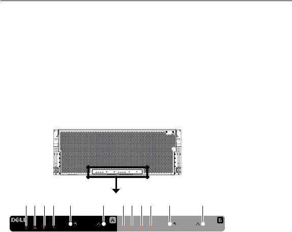
Front-panel features and indicators
1 |
2 |
3 |
4 |
5 |
6 |
7 |
8 |
9 |
10 |
11 |
12 |
1~6 for sled A |
7~12 for sled B |
Figure 1. Front-panel features and indicators
8

Item |
Indicator, Button, or |
Icon |
Description |
|
Connector |
|
|
|
|
|
|
1 |
Power indicator |
|
The power indicator glows when the system is |
|
|
|
turned on. |
2 |
ID indicator |
|
When a system identification button is pressed, |
|
|
|
the ID indicator blinks blue to help locate a |
|
|
|
particular system within a rack. |
3 |
Sled A HDD fault status |
|
The indicator blinks amber if an HDD experiences |
|
indicator |
|
an issue. |
4 |
System board status |
|
If the system is on, and in good health, the |
|
indicator |
|
indicator glows solid blue. |
|
|
|
The indicator blinks amber if the system is in |
|
|
|
standby, and if any issue exists (for example, a |
|
|
|
failed fan or HDD). |
5 |
Power button |
|
The power button controls the PSU output to the |
|
|
|
system. |
|
|
|
NOTE: On ACPI-compliant operating |
|
|
|
systems (OSs), turning off the system using |
|
|
|
the power button causes the system to |
|
|
|
perform a graceful shutdown before power |
|
|
|
to the system is turned off. |
6 |
System identification |
|
The identification button can be used to locate a |
|
button |
|
particular system within a rack. |
|
|
|
Press to toggle the system ID on and off. |
|
|
|
If the system stops responding during POST, |
|
|
|
press and hold the system ID button for more |
|
|
|
than five seconds to enter BIOS progress mode. |
|
|
|
To reset iDRAC (if not disabled in F2 iDRAC setup) |
|
|
|
press and hold the button for more than 15 |
|
|
|
seconds. |
7 |
Power indicator |
|
The power indicator glows when the system is |
|
|
|
turned on. |
8 |
ID indicator |
|
When a system identification button is pressed, |
|
|
|
the ID indicator blinks blue to help locate a |
|
|
|
particular system within a rack. |
9 |
Sled B HDD fault status |
|
The indicator blinks amber if an HDD experiences |
|
indicator |
|
an issue. |
10 |
System board status |
|
If the system is on, and in good health, the |
|
indicator |
|
indicator glows solid blue. |
The indicator blinks amber if the system is in standby, and if any issue exists (for example, a failed fan or HDD).
9

Item |
Indicator, Button, or |
Icon |
Description |
|
Connector |
|
|
|
|
|
|
11 |
Power button |
|
The power button controls the PSU output to the |
|
|
|
system. |
NOTE: On ACPI-compliant operating systems, turning off the system using the power button causes the system to perform a graceful shutdown before power to the system is turned off.
12 |
System identification |
The identification button can be used to locate a |
|
button |
particular system within a rack. |
Press to toggle the system ID on and off.
If the system stops responding during POST, press and hold the system ID button for more than five seconds to enter BIOS progress mode.
To reset iDRAC (if not disabled in F2 iDRAC setup) press and hold the button for more than 15 seconds.
 NOTE: Features of sled B are for dual-node systems only.
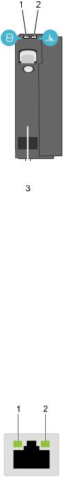
Back-panel features and indicators
1 2 |
3 4 5 6 7 |
8 9 |
10 11 |
12 |
13 |
14 15 |
Sled B |
|
|
|
|
|
|
Sled A |
|
|
|
|
|
|
|
17 |
|
16 |
Figure 2. Back-panel features and indicators |
|
||
|
|
|
|
Item |
Indicator, Button, or |
Icon |
Description |
|
Connector |
|
|
|
|
|
|
1 |
Blade EN connector |
|
This function is reserved. |
|
(optional) |
|
|
10
Item |
Indicator, Button, or |
Icon |
Description |
|
Connector |
|
|
|
|
|
|
2 |
Serial connector |
|
Enables you to connect a serial device to the |
|
|
|
system. |
3 |
Video connector |
|
Enables you to connect a VGA display to the |
|
|
|
system. |
4 |
Ethernet connector 1 |
|
Integrated 10/100/1000 Mbps NIC connector. |
5 |
Ethernet connector 2 |
|
Integrated 10/100/1000 Mbps NIC connector. |
6 |
USB connector |
|
Enables you to connect USB devices to the |
|
|
|
system. The port is USB 2.0-compliant. |
7 |
SD vFlash card slot |
|
Provides persistent on-demand local storage and |
|
|
|
a custom deployment environment that allows |
|
|
|
automation of server configuration, scripts and |
|
|
|
imaging. See the Integrated Dell Remote Access |
|
|
|
User’s Guide at dell.com/idracmanuals. |
8 |
USB connector |
|
Enables you to connect USB devices to the |
|
|
|
system. The port is USB 3.0-compliant. |
9 |
Dedicated Ethernet port |
|
Dedicated management port on the iDRAC ports |
|
|
|
card. |
10 |
System identification |
|
The identification button can be used to locate a |
|
button |
|
particular system within a rack. |
|
|
|
Press to toggle the system ID on and off. |
|
|
|
If the system stops responding during POST, |
|
|
|
press and hold the system ID button for more |
|
|
|
than five seconds to enter BIOS progress mode. |
|
|
|
To reset the iDRAC (if not disabled in F2 iDRAC |
|
|
|
setup) press and hold the button for more than |
|
|
|
15 seconds. |
11 |
Ethernet connector 3 |
|
Integrated 10/100/1000 Mbps NIC connector. |
12 |
Ethernet connector 4 |
|
Integrated 10/100/1000 Mbps NIC connector. |
13 |
Power button |
|
The power button controls the PSU output to the |
|
|
|
system. |
|
|
|
NOTE: On ACPI-compliant operating |
|
|
|
systems (OSs), turning off the system using |
|
|
|
the power button causes the system to |
|
|
|
perform a graceful shutdown before power |
|
|
|
to the system is turned off. |
14 |
Boot HDD A |
|
2.5-inch boot HDD. |
15 |
Boot HDD B |
|
2.5-inch boot HDD. |
11

Item |
Indicator, Button, or |
Icon |
Description |
|
Connector |
|
|
|
|
|
|
16 |
Power supply units |
|
Two redundant power supply units (PSUs) for sled |
|
|
|
A. |
17 |
Power supply units |
|
Two redundant power supply units (PSUs) for sled |
|
|
|
B. |
 NOTE: Features of sled B are for dual-node systems only.
NOTE: A dummy sled will be installed over sled B compartment and two dummy PSUs over the PSU slots for sled B for the single-node system.
HDD indicator codes
Figure 3. 2.5-inch HDD indicator
1 |
HDD activity indicator |
2 |
HDD |
NOTE: If the HDD is in Advanced Host Controller Interface (AHCI) mode, the status indicator (on the right side) does not function and remains off.
 NOTE: The function of the status indicator may vary depending on the HDD type.
12
|
|
|
|
|
|
|
|
|
|
|
|
|
|
|
|
|
|
|
|
|
|
|
|
|
|
|
|
|
|
|
|
|
|
|
|
|
|
|
|
|
|
|
|
|
|
|
|
|
Figure 4. 3.5-inch HDD indicators |
|
|
||||
1 |
|
|
|
HDD activity indicator |
2 |
HDD status indicator |
3 |
|
|
|
HDD |
|
|
|
|
|
||||
Drive-status indicator pattern (RAID only) |
|
Condition |
||||
|
|
|
||||
Blinks green two times per second |
|
Identifying drive or preparing for removal. |
||||
Off |
|
|
|
Normal operation |
||
Solid orange |
|
|
|
Drive failed |
||
Steady green |
|
|
|
Drive online |
||
NIC indicator codes
Figure 5. NIC indicators
1 |
link indicator |
2 |
activity indicator |
13
Indicator pattern |
Description |
|
|
Link and activity indicators are OFF |
The NIC is not connected to the network. |
Link indicator is green |
The NIC is connected to a valid network at its |
|
maximum port speed (1 Gbps). |
Link indicator is yellow |
The NIC is connected to a valid network at less than its |
|
maximum port speed. |
Activity indicator is blinking green |
Network data is being sent or received. |
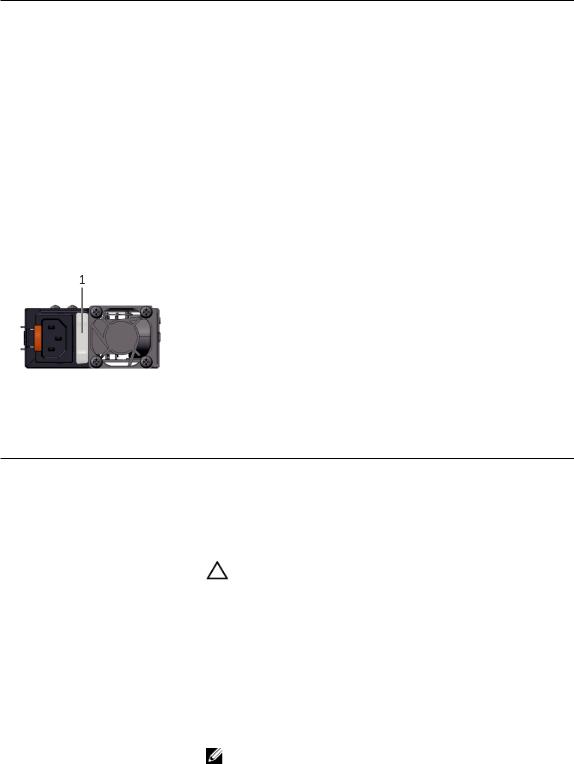
Indicator codes for the redundant PSU
Each AC PSU has an illuminated translucent handle that indicates whether power is present or whether a power fault has occurred.
Figure 6. AC PSU status indicator
1 AC PSU status indicator/handle
Indicator pattern |
Description |
|
|
Green |
A valid power source is connected to the PSU and the PSU is |
|
operational. |
Flashing green |
When updating the firmware of the PSU is being updated, the PSU |
|
handle flashes green. |
|
CAUTION: Do not disconnect the power cord or unplug |
|
the PSU when updating firmware. If firmware update is |
|
interrupted, the PSUs will not function. You must roll back |
|
the power supply firmware by using Life cycle controller. For |
|
more information, see Dell Lifecycle Controller User’s Guide |
|
at dell.com/idracmanuals. |
Flashing green and turns off |
When hot-adding a PSU, the PSU handle flashes green five times at |
|
4 Hz rate and turns off. This indicates that there is a PSU mismatch |
|
with respect to efficiency, feature set, health status, and supported |
|
voltage. Replace the PSU with a PSU that matches the capacity of |
|
the other PSU. |
|
NOTE: For AC PSUs, use only PSUs with the Extended Power |
|
Performance (EPP) label on the back. Mixing PSUs from earlier |
|
generations of Dell servers can result in a PSU mismatch |
|
condition or failure to turn on. |
14
Indicator pattern |
Description |
|
|
Flashing amber |
Indicates an issue with the PSU. |
|
CAUTION: When correcting a PSU mismatch, replace only |
|
the PSU with the flashing indicator. Swapping the other |
|
PSU to make a matched pair can result in an error condition |
|
and unexpected system shutdown. To change from a High |
|
Output configuration to a Low Output configuration or vice |
|
versa, you must turn off the system. |
|
CAUTION: If two PSUs are used, they must be of the same |
|
type and have the same maximum output power. |
|
CAUTION: Combining AC and DC PSUs is not supported and |
|
triggers a mismatch. |
Not lit |
Power is not connected. |
Documentation matrix
The documentation matrix provides information about documents that you can refer to for setting up and managing your system.
To… |
Refer to… |
|
|
Install your system into a rack |
Installing the rack and the server |
Configure and log in to iDRAC, set up managed and Integrated Dell Remote Access Controller User's management system, know the iDRAC features and Guide at dell.com/idracmanuals
troubleshoot using iDRAC
Know about the RACADM subcommands and supported RACADM interfaces
Start, enable and disable Lifecycle Controller, know the features, use and troubleshoot Lifecycle Controller
Use Lifecycle Controller Remote Services
Check the event and error messages generated by the system firmware and agents that monitor system components
RACADM Command Line Reference Guide for iDRAC and CMC at dell.com/idracmanuals
Dell Lifecycle Controller User’s Guide at dell.com/ idracmanuals
Dell Lifecycle Controller Remote Services Quick Start Guide at dell.com/idracmanuals
Dell Event and Error Messages Reference Guide at dell.com/idracmanuals
15
2
Performing initial system configuration
After you receive your system, you must set up your system, install the OS if it is not pre-installed, and set up and configure the system iDRAC IP address.
Setting up your system
1.Unpack the server.
2.Install the rack.
3.Install the server into the rack.
4.Install the hard disk drives into the chassis.
5.Connect the peripherals to the system.
6.Connect the system to its electrical outlet.
7.Turn the system on by pressing the power button or using iDRAC.
8.Turn on the attached peripherals.
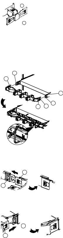
Installing the rack and the server
Installing the rails
1.Remove the inner member and slide the intermediate member back.
a.Press and remove the inner member.
b.Press down according to the arrow's direction, and slide the intermediate member back.
16

Figure 7. Removing the inner member and sliding the intermediate member back
2.Install the inner member onto the chassis and secure it with the screw.
 NOTE: Pay attention to the installation direction.
Figure 8. Installing the inner member onto the chassis
3. Secure the outer member and bracket into the rack with the screws for both the left and right sides.
17

Figure 9. Securing the outer member and bracket into the rack
4.Install the chassis into the rack.
a.Make sure that the ball-bearing retainer is at the front of the intermediate member.
b.Aim and push the inner member on the chassis into the intermediate member. The tab must be pressed when pushing the chassis in.
c.Secure the inner member with the screw.
Figure 10. Installing the chassis into the rack
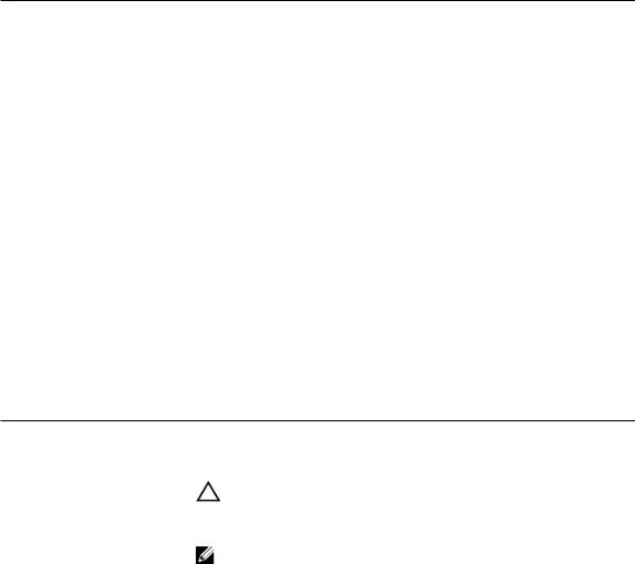
Installing the cable management arm (CMA)
1.Switch the left and right sides of the CMA by pressing the PUSH button and spin 180 degrees to change the direction.
18
2
 1
1
Figure 11. Switching the left and right sides of the CMA
2.The loop strap must be tied to the CMA crossbar.
 NOTE: The loop strap can be removed after the system arrives the final destination.
3.Install the CMA.
F
E
B
C A D
a. Install the CMA connector (A) into the CMA connector base on the inner member (B).
A
B
b. Install the CMA connector (C) into the CMA connector base on the outer member (D).
 D
D
C
19

c.Install the CMA connector beside the center CMA body (E) to the CMA connector base on the outer member (F).
F


 E
E
4.Release the CMA.
a. To release the outer member, press the PUSH button on tthe CMA plug-in part to draw it out.
1

 2
2
Then turn the CMA 90 degrees to the right, and press the PUSH button on the CMA plug-in part to draw it out.
|
A |
|
1 |
2 |
B |
b. To release the inner member, press the PUSH button on the CMA plug-in part to draw it out.
2  1
1


Setting up and configuring the iDRAC IP address
You can set up the Integrated Dell Remote Access Controller (iDRAC) IP address by using one of the following interfaces:
20
•iDRAC Settings utility
•Lifecycle Controller
•Dell OpenManage Deployment Toolkit
You can configure iDRAC IP address by using the following interfaces:
•iDRAC Web interface. For more information about the iDRAC Web interface, see the Integrated Dell Remote Access Controller User's Guide.
•Remote Access Controller ADMin (RACADM). For more information about the RACADM, see the RACADM Command Line Interface Reference Guide and the Integrated Dell Remote Access Controller User's Guide.
•Remote Services that includes Web Services Management (WS-Man). For more information about the Remote Services, see the Lifecycle Controller Remote Services Quick Start Guide.
For more information about setting up and configuring iDRAC, see the Integrated Dell Remote Access Controller User's Guide at dell.com/idracmanuals.
Configuring the iDRAC settings for the dedicated management port card
1.Turn on or restart your system.
2.Press F2 immediately after you see the following message:
F2 = System Setup
If your operating system begins to load before you press F2, enable the system to finish booting, and then restart your system and try again.
3.In the System Setup Main Menu page, click iDRAC Settings → Network.
4.If the dedicated management port card is installed:
By default, the NIC Selection option in Network Settings is set to Dedicated; the Register DRAC on DNS option in Common Settings is disabled.
You can also set the NIC Selection option to LOM1, LOM2, LOM3 or LOM4.
5.If the dedicated management port card is not installed:
By default, the NIC Selection option in Network Settings is set to LOM1; the Register DRAC on DNS option in Common Settings is disabled.
You can also set the NIC Selection option to LOM2, LOM3 or LOM4.
Logging in to iDRAC
You can log in to iDRAC as an iDRAC local user, a Microsoft Active Directory user, or a Lightweight Directory Access Protocol (LDAP) user. You can also log in by using Single Sign-On or a Smart Card. The default user name is root and password is calvin. For more information about logging in to iDRAC and iDRAC licenses, see the Integrated Dell Remote Access Controller User's Guide at dell.com/ idracmanuals.
You can also access iDRAC using RACADM. For more information about using RACADM, see the RACADM Command Line Interface Reference Guide and the Integrated Dell Remote Access Controller User's Guide available at dell.com/idracmanuals.
21

Installing the OS
If the server is shipped without an OS, install the supported OS on the server by using one of the following methods:
•For information about Dell Systems Management Tools and Documentation media, see the OS documentation at dell.com/operatingsystemmanuals.
•For information about Dell Lifecycle Controller, see the Lifecycle Controller documentation at dell. com/idracmanuals.
•For information about Dell OpenManage Deployment Toolkit, see the OpenManage documentation at dell.com/openmanagemanuals.
•Installation by using Preboot Execution Environment (PXE), Windows Deployment Services (WDS), or a DVD.
For information about the list of OSs supported on your system, see the OS support matrix at dell.com/ ossupport.
Managing your system remotely
To perform out-of-band systems management using iDRAC, you must configure iDRAC for remote accessibility, set up the management station and managed system, and configure the supported Web browsers. For more information about configuring iDRAC for remote accessibility, see the Integrated Dell Remote Access Controller User’s Guide at dell.com/idracmanuals.
You can also remotely monitor and manage the server by using the Dell OpenManage Server Administrator (OMSA) software and OpenManage Essentials (OME) systems management console. For more information about the Dell OMSA software and OME systems management console, see dell.com/ openmanagemanuals.
Downloading and installing drivers and firmware
It is recommended that you download and install the latest BIOS, drivers, and systems management firmware on your system.
Prerequisites
Ensure that you clear the web browser cache.
Steps
1.Go to dell.com/support/drivers.
2.In the Product support section, enter the Service Tag of your system in the Enter a Service Tag or Express Service Code field.
NOTE: If you do not have the Service Tag, select Auto-detect your product to enable the system to automatically detect your Service Tag, or select your product by clicking View products from the Browse for a product section.
3.Click Drivers and downloads.
The drivers that are applicable to your selection are displayed.
4.Download the drivers you require to a diskette drive, USB drive, CD, or DVD.
22
Installing the driver for the LSI 9311 card on a Ubuntu1404 system
1.Download the required driver (mpt3sas.ko) to a USB drive from dell.com/support/drivers.
2.When prompted by the Ubuntu installer CD, select Ubuntu Server for installation.
3.On the [!]Configure the C lock screen, press Ctrl + Alt + F1 to access a console.
4.Mount the USB drive with the driver by using the following command if the USB drive is mapped to the device name sda1 OR sdb1:
#mount –t vfat /dev/sda1 /mnt/usb
5.Change the directory to the folder with the driver.
6.Use the following commands:
#cp -f /LSI/mpt3sas.ko /lib/modules/3.13.0-24-generic/kernel/drivers/scsi
#insmod /lib/modules/3.13.0-24-generic/kernel/fs/configfs/configfs.ko
#insmod /lib/modules/3.13.0-24-generic/kernel/drivers/scsi/scsi_transport_ sas.ko
#insmod /lib/modules/3.13.0-24-generic/kernel/drivers/scsi/raid_class.ko
#insmod /lib/modules/3.13.0-24-generic/kernel/drivers/scsi/mpt3sas.ko
7.The driver gets loaded and detects the controller and the disks.
8.Press Ctrl + Alt + F1 to return to the installer screen.
9.Proceed with the OS installation.
23

3
Pre-operating system management applications
The pre-operating system management applications for your system help you manage different settings and features of your system without booting to the operating system.
Your system has the following pre-operating system management applications:
•System Setup
•Boot Manager
•Dell Lifecycle Controller
Navigation keys
The navigation keys can help you access the pre-operating system management applications.
Key |
Description |
|
|
Page Up |
Moves to the previous page. |
Page Down |
Moves to the next page. |
Up arrow |
Moves to the previous field. |
Down arrow |
Moves to the next field. |
Enter |
Enables you to type a value in the selected field (if applicable) or follow the link in |
|
the field. |
Spacebar |
Expands or collapses a drop-down list, if applicable. |
Tab |
Moves to the next focus area. |
|
NOTE: This feature is applicable for the standard graphical browser only. |
Esc |
Moves to the previous page until you view the main page. Pressing Esc in the main |
|
page exits System BIOS/iDRAC Settings/Device Settings/Service Tag Settings and |
|
proceeds with system boot. |
F1 |
Displays the System Setup help. |
About System Setup
Using System Setup, you can configure the BIOS settings, iDRAC settings, and device settings of your system.
24

You can access System Setup in two ways:
•Standard Graphical Browser — This is enabled by default.
•Text Browser — This is enabled using Console Redirection.
NOTE: By default, help text for the selected field is displayed in the graphical browser. To view the help text in the text browser, press F1.
Entering System Setup
1.Turn on or restart your system.
2.Press F2 immediately after you see the following message:
F2 = System Setup
If your operating system begins to load before you press F2, enable the system to finish booting, and then restart your system and try again.
System Setup Main Menu
Option |
Description |
|
|
System BIOS |
Enables you to configure BIOS settings. |
iDRAC Settings |
Enables you to configure iDRAC settings. |
|
The iDRAC Settings utility is an interface to set up and configure the |
|
iDRAC parameters by using UEFI. You can enable or disable various |
|
iDRAC parameters by using the iDRAC Settings utility. For more |
|
information about this utility, see the Integrated Dell Remote Access |
|
Controller User’s Guide at dell.com/idracmanuals. |
Device Settings |
Enables you to configure device settings. |
System BIOS page
By using the System BIOS page, you can view the BIOS settings and edit specific functions such as Boot order, system password, setup password, setting the RAID mode, and enabling or disabling USB ports.
In the System Setup Main Menu, click System BIOS.
Menu Item |
Description |
|
|
System Information |
Displays information about the system such as the system model name, |
|
BIOS version and Service Tag. |
Memory Settings |
Displays information and options related to the installed memory. |
Processor Settings |
Displays information and options related to the processor such as speed |
|
and cache size. |
SATA Settings |
Displays options to enable or disable the integrated Serial ATA (SATA) |
|
controller and ports. |
Boot Settings |
Displays options to specify the boot mode (BIOS or UEFI). Enables you |
|
to modify UEFI and BIOS boot settings. |
25

Menu Item |
Description |
|
|
Integrated Devices |
Displays options to enable or disable integrated device controllers and |
|
ports, and to specify related features and options. |
Serial Communication |
Displays options to enable or disable the serial ports and specify related |
|
features and options. |
System Profile Settings |
Displays options to change the processor power management settings, |
|
memory frequency, and so on. |
System Security |
Displays options to configure the system security settings like, system |
|
password, setup password and TPM security. It also enables or disables |
|
support for the power and NMI buttons on the system. |
Miscellaneous Settings |
Displays options to change the system date and time. |
System Information page
You can use the System Information page to view system properties such as Service Tag, system model, and the BIOS version.
To view the System Information, click System Setup Main Menu → System BIOS → System Information.
Menu Item |
Description |
|
|
System Model Name |
Displays the system model name. |
System BIOS Version |
Displays the BIOS version installed on the system. |
System Management Engine Displays the latest revision of the Management Engine firmware.
Version
System Service Tag |
Displays the system Service Tag. |
System Manufacturer |
Displays the name of the system manufacturer. |
System Manufacturer Contact Displays the contact information of the system manufacturer.
Information
System CPLD Version |
Displays the latest revision of the system CPLD firmware. |
UEFI Compliance Version Displays the system firmware UEFI compliance level.
Memory Settings page
You can use the Memory Settings page to view all the memory settings and enable or disable specific memory functions such as system memory testing and node interleaving.
To view the Memory Setting page, click System Setup Main Menu → System BIOS → Memory Settings.
Menu Item |
Description |
|
|
System Memory Size |
Displays the amount of memory installed in the system. |
System Memory Type |
Displays the type of memory installed in the system. |
26

Menu Item |
Description |
|
|
System Memory Speed |
Displays the system memory speed. |
System Memory Voltage |
Displays the system memory voltage. |
Video Memory |
Displays the amount of video memory utilized. |
System Memory Testing |
Specifies whether system memory tests are run during system boot. |
|
Options are Enabled and Disabled. By default, the System Memory |
|
Testing option is set to Disabled. |
Memory Operating Mode |
Specifies the memory operating mode. The options available are |
|
Optimizer Mode and Spare Mode. By default, the Memory Operating |
|
Mode option is set to Optimizer Mode. |
|
NOTE: The Memory Operating Mode can have different defaults |
|
and available options based on the memory configuration of your |
|
system. |
Node Interleaving |
Specifies if Non-Uniform Memory architecture (NUMA) is supported. If |
|
this field is Enabled, memory interleaving is supported if a symmetric |
|
memory configuration is installed. If Disabled, the system supports |
|
NUMA (asymmetric) memory configurations. By default, the Node |
|
Interleaving option is set to Disabled. |
Snoop Mode |
Specifies the Snoop Mode options. Snoop Mode options available are |
|
Early Snoop and Home Snoop. By default, the Snoop Mode option is set |
|
to Early Snoop. The field is only available when the Node Interleaving |
|
optoin is set to Disabled. |
Processor Settings page
You can use the Processor Settings page to view the processor settings and perform specific functions such as enabling virtualization technology, hardware prefetcher, and logical processor idling.
To view the Processor Settings page, click System Setup Main Menu → System BIOS → Processor Settings.
Menu Item |
Description |
|
|
QPI Speed |
Specifies the QPI (QuickPath Interconnect). The options available are |
|
Maximum data rate and 6.4 GT/s. By default, the QPI Speed option is |
|
set to Maximum data rate. |
Alternate RTID (Requestor |
Enables you to allocate more RTIDs to the remote socket, thereby |
Transaction ID) Setting |
increasing cache performance between the sockets or easing work |
|
in normal mode for NUMA. By default, the Alternate RTID (Requestor |
|
Transaction ID) Setting is set to Disabled. |
Virtualization Technology |
Enables or disables the additional hardware capabilities provided for |
|
virtualization. By default, the Virtualization Technology option is set to |
|
Enabled. |
27

Menu Item |
Description |
Address Translation Service Defines the Address Translation Cache (ATC) for devices to cache the (ATS) DMA transactions. This field provides an interface to a chipset's Address
Translation and Protection Table to translate DMA addresses to host addresses. By default, the option is set to Enabled.
Adjacent Cache Line Prefetch Optimizes the system for applications that require high utilization of sequential memory access. By default, the Adjacent Cache Line Prefetch option is set to Enabled. You can disable this option for applications that require high utilization of random memory access.
Hardware Prefetcher |
Enables or disables the hardware prefetcher. By default, the Hardware |
|
Prefetcher option is set to Enabled. |
DCU Streamer Prefetcher |
Allows you to enable or disable the Data Cache Unit (DCU) streamer |
|
prefetcher. By default, the DCU Streamer Prefetcher option is set to |
|
Enabled. |
DCU IP Prefetcher |
Enables or disables the Data Cache Unit (DCU) IP prefetcher. By default, |
|
the DCU IP Prefetcher option is set to Enabled. |
Logical Processor Idling |
Enables or disables the operating system capability to put logical |
|
processors in the idling state in order to reduce power consumption. By |
|
default, the option is set to Disabled. |
Configurable TDP |
Allows reconfiguration of Thermal Design Power (TDP) to lower levels. |
|
TDP refers to the maximum amount of power the cooling system is |
|
required to dissipate. |
X2Apic Mode |
Enables or disables the X2Apic mode. |
Number of Cores per |
Controls the number of enabled cores in each processor. By default, the |
Processor |
Number of Cores per Processor option is set to All. |
Processor 64-bit Support |
Specifies if the processors support 64-bit extensions. |
Processor Core Speed |
Displays the maximum core frequency of the processor. |
Processor Bus Speed |
Displays the bus speed of the processor. |
|
NOTE: The processor bus speed option displays only when both |
|
processors are installed. |
Processor 1 |
NOTE: Depending on the number of installed CPUs, there may be |
|
up to two processor listings. The following settings are displayed for |
|
each processor installed in the system. |
Family-Model-Stepping |
Displays the family, model and stepping of the processor as defined by |
|
Intel. |
Brand |
Displays the brand name reported by the processor. |
Level 2 Cache |
Displays the total L2 cache. |
Level 3 Cache |
Displays the total L3 cache. |
28

Menu Item |
Description |
|
|
Number of Cores |
Displays the number of cores per processor. |
Processor 2 |
NOTE: Depending on the number of installed CPUs, there may be |
|
up to two processor listings. The following settings are displayed for |
|
each processor installed in the system. |
Family-Model-Stepping |
Displays the family, model and stepping of the processor as defined by |
|
Intel. |
Brand |
Displays the brand name reported by the processor. |
Level 2 Cache |
Displays the total L2 cache. |
Level 3 Cache |
Displays the total L3 cache. |
Number of Cores |
Displays the number of cores per processor. |
SATA Settings page
You can use the SATA Settings page to view the SATA settings of SATA devices and enable RAID on your system.
To view the SATA Settings page, click System Setup Main Menu → System BIOS → SATA Settings.
Menu Item |
Description |
|
|
Embedded SATA |
Enables the embedded SATA to be set to Off, ATA, AHCI, or RAID |
|
modes. By default, the Embedded SATA option is set to AHCI. |
Security Freeze Lock |
Sends Security Freeze Lock command to the Embedded SATA drives |
|
during POST. This option is applicable only to ATA and AHCI mode. |
Write Cache |
Enables or disables the command for Embedded SATA drives during |
|
POST. |
Port A – H (reserved) |
Sets the drive type of the selected device. For Embedded SATA settings |
|
in ATA mode, set this field to Auto to enable BIOS support. Set it to OFF |
|
to turn off BIOS support. |
|
For AHCI mode or RAID mode, BIOS always enables support. |
Model |
Displays the drive model of the selected device. |
Drive Type |
Displays the type of drive attached to the SATA port. |
Capacity |
Displays the total storage capacity of the HDD. The field is undefined for |
|
removable media devices such as optical drives. |
Port I (boot drive A) |
Sets the drive type of the selected device. For Embedded SATA settings |
|
in ATA mode, set this field to Auto to enable BIOS support. Set it to OFF |
|
to turn off BIOS support. |
|
For AHCI mode or RAID mode, BIOS always enables support. |
Model |
Displays the drive model of the selected device. |
29
Menu Item |
Description |
|
|
Drive Type |
Displays the type of drive attached to the SATA port. |
Capacity |
Displays the total capacity of the HDD. The field is undefined for |
|
removable media devices such as optical drives. |
Port J (boot drive B) |
Sets the drive type of the selected device. For Embedded SATA settings |
|
in ATA mode, set this field to Auto to enable BIOS support. Set it to OFF |
|
to turn off BIOS support. |
|
For AHCI mode or RAID mode, BIOS always enables support. |
Model |
Displays the drive model of the selected device. |
Drive Type |
Displays the type of drive attached to the SATA port. |
Capacity |
Displays the total capacity of the HDD. The field is undefined for |
|
removable media devices such as optical drives. |
Boot Settings page
You can use the Boot Settings page to set the Boot mode to either BIOS or UEFI. It also enables you to specify the boot order.
To view the Boot Settings page, click System Setup Main Menu → System BIOS → Boot Settings.
Menu Item |
Description |
|
|
Boot Mode |
Enables you to set the boot mode of the system. |
|
CAUTION: Switching the boot mode may prevent the system from |
|
booting if the operating system is not installed in the same boot |
|
mode. |
|
NOTE: Setting this field to UEFI disables the BIOS Boot Settings |
|
menu. Setting this field to BIOS disables the UEFI Boot Settings |
|
menu. |
|
If the operating system supports UEFI, you can set this option to UEFI. |
|
Setting this field to BIOS enables compatibility with non-UEFI operating |
|
systems. By default, the Boot Mode option is set to BIOS. |
Boot Sequence Retry |
Enables or disables the Boot Sequence Retry feature. If this field is |
|
enabled and the system fails to boot, the system reattempts the boot |
|
sequence after 30 seconds. By default, the Boot Sequence Retry option |
|
is set to Enabled. |
Hard-Disk Failover |
Specifies which devices in the Hard-Disk Drive Sequence are attempted |
|
in the boot sequence. When the option is Disabled, only the first HDD in |
|
the list is attempted to boot. When set to Enabled, all hard disk devices |
|
are attempted in order, as listed in the Hard-Disk Drive Sequence. This |
|
option is not enabled for UEFI Boot Mode. |
Boot Option Settings |
Configures the boot sequence and the boot devices. |
30
Loading...