


Delfield F17VD84, F18VD50, F18VD82, F2984VDL, F2984VDR Service Manual
...SERVICE
MANUAL
Versa Drawer
Refrigeration Units
Please read this manual completely before attempting to service this equipment.
MODELS:
F17VD84 18650VDL F18VD50 18650VDR F18VD82 18682VDL F2984VDL 18682VDR F2984VDR
1 |
3 |
2 |
4 |
1
2
1
2
RETAIN THIS MANUAL FOR FUTURE REFERENCE.
Delfield 980 S. Isabella Rd., Mt. Pleasant, MI 48858 (989) 773-7981 or (800) 733-8829 • Fax (989) 773-3210 www.delfield.com
February 2007

Delfield
IMPORTANT WARNINGS AND SAFETY INFORMATION
 WARNING
ANY REFRIGERATION SERVICE PROCEDURES DESCRIBED IN THIS MANUAL MUST BE PERFORMED BY A CERTIFIED EPA TECHNICIAN.
Read this manual thoroughly before installing, operating, or performing maintenance on the equipment.
FAILURE TO FOLLOW INSTRUCTIONS IN THIS MANUAL CAN CAUSE PROPERTY DAMAGE, INJURY OR DEATH.
•Do not store or use gasoline or other flammable vapors or liquids in the vicinity of this or any other appliance.
•Unless all covers and access panels are in place and properly secured, do not operate this equipment.
•Damp or wet hands may stick to cold surfaces.
•Allow heated equipment to cool down before attempting to clean or service.
•Read and understand instruction manuals and labels. Learn all applications and restrictions for the service performed.
•Do not remove ground prong from service equipment cords.
•Use extension cords rated for the intended service and as short in length as possible.
•Use refrigerant hoses SAE J196-1992 approved with a shutoff device within 12 inches of the ends.
•Make sure recovery tanks are DOT approved for use with the type of refrigerant being serviced.
•Service units only in well ventilated areas using mechanical ventilation systems.
•Follow all accessory advisories and instructions.
•Do not operate any unit with defective or damaged parts.
 WARNING
Serious injury or death can occur from inhaling high concentrations of refrigerant vapors. These vapors also reduce oxygen levels in confined areas. Contact with liquid can cause frostbite. All containers, equipment and hoses are under high pressure. Do not puncture or damage these components.
 CAUTION
Observe the following:
•Keep the equipment area free and clear of combustible material.
•Maintain adequate clearance for air openings.
•Operate equipment only on the type of electricity indicated on the data plate.
•Unplug the unit before making any repairs.
•Handle all refrigerant hoses, recovery tanks, lines and other vessels as containers under pressure at all times.
•Retain this manual for future reference.
2

|
Versa Drawer Refrigeration Units |
TABLE OF CONTENTS |
|
IMPORTANT WARNINGS AND SAFETY INFORMATION |
....................................................................... 2 |
INTRODUCTION ..................................................................................................................................... |
5 |
GENERAL ........................................................................................................................................ |
5 |
MODEL NUMBER ............................................................................................................................ |
5 |
SERIAL NUMBER ............................................................................................................................ |
5 |
HEATING SYSTEM .......................................................................................................................... |
5 |
REFRIGERATION SYSTEM ............................................................................................................. |
5 |
TEMPERATURE MONITORING ....................................................................................................... |
5 |
CONTROLLER ................................................................................................................................. |
5 |
SPECIFICATIONS ............................................................................................................................ |
6 |
Refrigeration System .................................................................................................................. |
6 |
Electrical Connections ............................................................................................................... |
6 |
Drawers ...................................................................................................................................... |
6 |
Legs ........................................................................................................................................... |
6 |
Casters ...................................................................................................................................... |
6 |
INSTALLATION ................................................................................................................................. |
6 |
OPERATION ..................................................................................................................................... |
6 |
OPERATOR MAINTENANCE ........................................................................................................... |
6 |
COMPONENT REMOVAL AND REPLACEMENT ................................................................................... |
7 |
COVERS AND PANELS ................................................................................................................... |
7 |
Front Louvered Panel .................................................................................................................. |
7 |
Louvered Access End Panel ...................................................................................................... |
7 |
Rear Panel ................................................................................................................................. |
7 |
DRAWER ASSEMBLY ...................................................................................................................... |
7 |
Drawer Removal ......................................................................................................................... |
7 |
Drawer Gasket ........................................................................................................................... |
7 |
Drawer Front Assembly .............................................................................................................. |
7 |
Return Air Baffle ......................................................................................................................... |
8 |
Drawer Switch ............................................................................................................................ |
8 |
EVAPORATOR COIL ASSEMBLY COVER ....................................................................................... |
8 |
EVAPORATOR COIL ASSEMBLY .................................................................................................... |
9 |
EXPANSION VALVE ......................................................................................................................... |
9 |
CONDENSER FAN BLADE .............................................................................................................. |
9 |
CONDENSER FAN MOTOR ........................................................................................................... |
10 |
CONDENSER COIL ........................................................................................................................ |
10 |
COMPRESSOR .............................................................................................................................. |
10 |
ACCUMULATOR/RECEIVER .......................................................................................................... |
11 |
FILTER DRYER .............................................................................................................................. |
11 |
SOLENOID VALVES ...................................................................................................................... |
11 |
PRESSURE TRANSDUCER ........................................................................................................... |
12 |
BOX TEMPERATURE SENSOR ..................................................................................................... |
12 |
3

Delfield
DISPLAY CONTROL BOARD ......................................................................................................... |
12 |
ELECTRIC INPUT/OUTPUT (I/O) CONTROL BOARD .................................................................... |
13 |
LEGS .......................................................................................................................................... |
13 |
CASTERS ...................................................................................................................................... |
17 |
CONTROL CONSOLE ........................................................................................................................... |
14 |
CHANGING DRAWER MODES ...................................................................................................... |
14 |
MANUAL DEFROST ....................................................................................................................... |
14 |
PROGRAM MENU .......................................................................................................................... |
14 |
SET POINTS .................................................................................................................................. |
15 |
CONFIGURATION .......................................................................................................................... |
15 |
DIAGNOSTICS ............................................................................................................................... |
15 |
TIME AND DATE ............................................................................................................................ |
15 |
SOFTWARE VERSIONS ................................................................................................................ |
15 |
TROUBLESHOOTING ........................................................................................................................... |
16 |
GENERAL ...................................................................................................................................... |
16 |
DIAGNOSTICS ............................................................................................................................... |
16 |
TROUBLESHOOTING CHART ....................................................................................................... |
16 |
CIRCUIT AND CONTROL DIAGRAMS ................................................................................................. |
18 |
STANDARD LABOR GUIDELINES TO REPAIR OR REPLACE PARTS |
|
ON DELFIELD EQUIPMENT ................................................................................................................ |
23 |
MANUFACTURER'S LIMITED LIFETIME WARRANTY ......................................................................... |
24 |
STANDARD ONEYEAR WARRANTY .................................................................................................... |
25 |
ADDITIONAL FOUR YEAR PROTECTION PLAN (for Motor-Compressor only) ..................................... |
26 |
4
Versa Drawer Refrigeration Units
INTRODUCTION
GENERAL
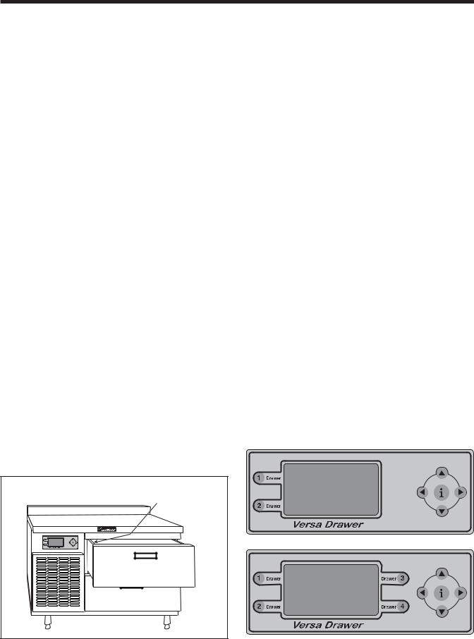
Versa Drawer series refrigeration units have two or four drawers, each of which can operate in one of four modes at any time. The two-drawer and four-drawer models feature countertop-height stainless steel work surfaces. A two-drawer Lo Profile unit is also available.
Refrigeration mode: The drawer operates as a refrigerator, maintaining the refrigeration set point between 32°F and 41°F.
Freezer mode: The drawer operates as a self-defrosting freezer, maintaining the freezer set point between -5°F and 5°F.
Thaw Cabinet mode: The drawer operates as a thaw cabinet, maintaining the thaw cabinet set point between 32°F and 50°F using hot gas and refrigeration as required for a fixed time period. Once the period has elapsed, the drawer mode is changed to refrigeration mode.
Convenience Chiller mode: The drawer operates as a convenience chiller, maintaining the convenience chiller set point between -5°F and 25°F for four hours. Once the period has elapsed, the drawer mode is changed to refrigeration mode.
All units have stainless steel exteriors and interiors. Drawer gaskets are magnetic and mount to the drawer, snapping in place. The gaskets are removable without tools.
This manual covers standard units. If you have a custom unit, consult the service department at 800-733-8829.
SERIAL AND MODEL NUMBERS
The serial and model numbers are located inside Drawer 1 on the left side.
Serial and Model Number
location
THAW SYSTEM
Hot gas is used for the thaw cabinet operation and the defrost mode. A hot gas solenoid controls the heat. In the defrost mode the hot gas will be used to warm the evaporator coil when a drawer is used as a thaw cabinet. The hot gas solenoid will open to maintain drawer temperature.
REFRIGERATION SYSTEM
The refrigeration system is used in all modes. The refrigerationsolenoidcontrolsrefrigerant.Twocompressors run in parallel operation in a four-drawer system while one compressor operates the two-drawer system.
TEMPERATURE MONITORING
Temperature sensors are located in each drawer. The drawer temperature is displayed on the control panel.
CONTROLLER
The controller provides information indicating the drawer mode. In addition, the actual temperature of the drawer is displayed. The push button tabs, located next to the display screen, represent each drawer. These tabs are used to select the drawer for control. The control display located on the right side of the control panel is used to toggle between control screens and to select drawer modes and temperatures.
5

Delfield
SPECIFICATIONS
MODEL |
|
|
COMP |
|
HEIGHT |
WIDTH |
DEPTH |
NO. OF |
SHIP |
NEMA |
NUMBER |
VOLTS |
HP |
POS |
AMPS |
(inches) |
(inches) |
(inches) |
DRAWERS |
WGT |
PLUG |
|
|
|
|
|
|
|
|
|
(lbs) |
|
F18VD50 |
115 |
1/3 |
Left |
6.0 |
36 |
50 |
31.5 |
2 |
520 |
5-15P |
|
|
|
|
|
|
|
|
|
|
|
F18VD82 |
115 |
(2) 1/3 |
Left |
12.0 |
36 |
82 |
31.5 |
4 |
720 |
5-15P |
|
|
|
|
|
|
|
|
|
|
|
F17VD84 |
115 |
1/3 |
Left |
6.0 |
36 |
84 |
31.5 |
2 |
750 |
5-15P |
|
|
|
|
|
|
|
|
|
|
|
F2984VDL |
115 |
1/3 |
Left |
6.0 |
26 |
84 |
31.5 |
2 |
850 |
5-15P |
|
|
|
|
|
|
|
|
|
|
|
F2984VDR |
115 |
1/3 |
Right |
6.0 |
26 |
84 |
31.5 |
2 |
850 |
5-15P |
|
|
|
|
|
|
|
|
|
|
|
18650VDL |
115 |
1/3 |
Left |
6.0 |
34 |
50 |
31.5 |
2 |
520 |
5-15P |
|
|
|
|
|
|
|
|
|
|
|
18650VDR |
115 |
1/3 |
Right |
6.0 |
34 |
50 |
31.5 |
2 |
520 |
5-15P |
|
|
|
|
|
|
|
|
|
|
|
18682VDL |
115 |
(2) 1/3 |
Left |
12.0 |
34 |
82 |
31.5 |
4 |
720 |
5-15P |
|
|
|
|
|
|
|
|
|
|
|
18682VDR |
115 |
(2) 1/3 |
Right |
12.0 |
34 |
82 |
31.5 |
4 |
720 |
5-15P |
|
|
|
|
|
|
|
|
|
|
|
Refrigeration System
HFC-404A Refrigerant
Electrical Connections
115 Volt, 60 Hertz, single phase, 3-wire, grounded, 8' cord with plug
Drawers
32", 11-12 gauge stainless steel, 12" X 20" pan capacity
Legs
6" adjustable
Casters
5" casters, with and without brakes
INSTALLATION
See the Installation and Operation Manual for installation information.
OPERATION
See the Installation and Operation Manual for operational information.
OPERATOR MAINTENANCE
See the Installation and Operation Manual for operator maintenance information.
6
Versa Drawer Refrigeration Units
COMPONENT REMOVAL AND REPLACEMENT
Lo Profile and 2-Drawer refrigeration units use one compressor, one accumulator, one receiver and four solenoids. In addition, one evaporator is used for each drawer along with support components. The 4-Drawer refrigeration unit uses two complete 2-Drawer units. Component removal and replacement is similar for both types.
Perform the following procedures to remove and replace parts. To eliminate mistakes when ordering parts, always provide the following information:
•Model Number
•Serial Number
COVERS AND PANELS
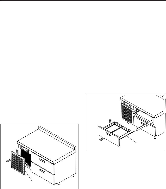
Front Louvered Panel
NOTE: Front louvered panel removal is similar for all models.
1.Lift up on louver from bottom and pull away from unit (Figure 1).
2.Reverse the above step to install the front louvered panel.
Front louvered panel |
Figure 1. Front Louvered Panel
Louvered Access End Panel
NOTE: Louvered access end panel removal is similar for all models.
1.While supporting the louvered access end panel, remove mounting screws.
2.Lift louvered access end panel out and up to remove.
3.Reverse the above steps to install the louvered access end panel.
Rear Panel
1.While supporting the rear panel, remove 11 screws.
2.Remove the rear panel from the unit.
3.Reverse the above steps to install the rear panel.
DRAWER ASSEMBLY
Drawer Removal
1.Empty the drawer.
2.Pull and lift the drawer to remove it from the unit (Figure 2).
Drawer |
Figure 2. Drawer Removal
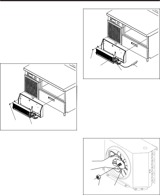
Drawer Gasket
The drawer gasket is installed on the inner side of the drawer front and fitted into a slot (Figure 3).
1.Remove the drawer gasket by carefully pulling the drawer gasket out of the groove.
2.Reverse the above step to install the drawer gasket.
Drawer Front Assembly
1.Remove the drawer from the refrigeration unit (Figure 3).
2.Place the drawer on a solid surface with the drawer front assembly down.
3.Remove six screws securing the drawer front assembly to the drawer.
4.Reverse the above steps to install the drawer front assembly.
7

Delfield |
|
|
|
|
|
|
Drawer |
|
|
|
switch |
|
|
Figure 5. |
Drawer Switch |
|
Screw |
4. Tag and disconnect the wiring harness from the |
|
|
|
||
|
Drawer |
drawer switch. |
|
|
|
|
|
Drawer |
gasket |
5. Reverse the above steps to install a replacement |
|
|
drawer switch. |
|
|
front |
|
|
|
|
|
|
|
Figure 3. Drawer Front Assembly
Return Air Baffle
1.Remove screws from return air baffle (Figure 4).
2.Remove blue wires from drawer switch while supporting air baffle.
3.Reverse the above steps to install the return air baffle.
Return air |
6 Screws |
baffle |
|
Figure 4. Return Air Baffle
Drawer Switch
1.Disconnect power from the refrigeration unit.
2.Remove the drawer as described previously.
3.Reach inside the box and carefully remove the drawer switch out of the mounting slot (Figure 5).
EVAPORATOR COIL
ASSEMBLY COVER
NOTE: Evaporator coil assembly cover removal is similar for all models.
1.The evaporator coil assembly cover is mounted behind the drawer (Figure 6).
2.Reach inside the box and remove four screws from the front of the evaporator coil assembly cover.
Evaporator coil assembly |
Evaporator coil assembly cover |
Figure 6. Evaporator Coil Assembly Cover
3.Tag and disconnect the fan electrical connectors.
4.Remove the evaporator coil assembly cover from the box.
5.Reverse the above steps to install the evaporator coil assembly cover.
8
Versa Drawer Refrigeration Units
EVAPORATOR COIL ASSEMBLY
1.Disconnect power from the refrigeration unit.
2.Remove the drawer as described above.
3.Remove the rear panel as described in COVERS AND PANELS.
4.Remove the evaporator coil assembly cover as described previously.
5.Follow the EPA guidelines for RECOVERY, PURGING/TESTING AND RECHARGING REFRIGERATION UNIT to recover the refrigerant from the refrigeration system.
Screw |
Evaporator coil assembly |
Figure 7. Evaporator Coil Assembly Removal
6.From the rear of the refrigeration unit, unsolder the refrigeration lines from the evaporator coil assembly.
7.Carefully remove the expansion valve thermocouple from evaporator line.
8.Remove the evaporator coil assembly from the unit (Figure 7).
9.Reverse the above steps to install a replacement or repaired evaporator coil assembly. Recharge the system as described in the EPA guidelines for RECOVERY, PURGING/TESTING AND RECHARGING REFRIGERATION UNIT.
EXPANSION VALVE
1.Disconnect power from the refrigeration unit.
2.Remove the evaporator coil assembly cover as described in COVERS AND PANELS.
3.Remove the expansion valve thermocouple from the evaporator line.
Screw |
|
Evaporator coil |
Thermocouple |
assembly |
Expansion |
|
|
|
valve (TXV) |
Figure 8. Expansion Valve and Thermocouple
4.Reach inside the drawer box and unsolder the refrigeration lines. Remove the expansion valve and thermocouple from the evaporator housing (Figure 8).
5.Reverse the above steps to install a replacement expansion valve.
CONDENSER FAN BLADE
1.Disconnect power from the refrigeration unit.
2.Remove the louvered access end panel as described in COVERS AND PANELS.
Nut |
Condenser |
|
fan blade |
Figure 9. Condenser Fan Blade
3.While holding the condenser fan blade (Figure 9), remove the lock nut from the center of the condenser fan blade.
4.Reverse the above steps to install the condenser fan blade.
9
 Loading...