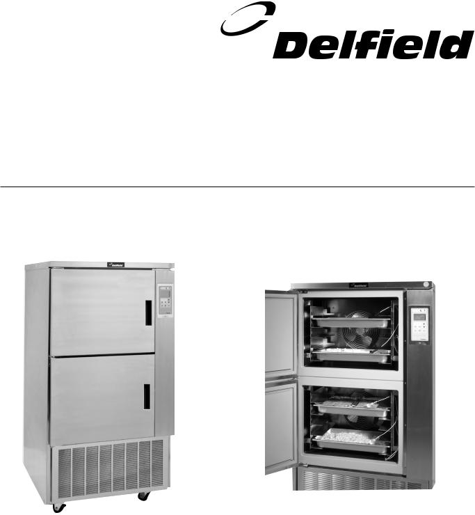
Delfield DBC-5 Operators Manual

SAFE CHILL™ BLAST CHILLERS
Service, Installation and Care Manual
Please read this manual completely before attempting to install or operate this equipment! Notify carrier of damage! Inspect all components immediately. See page 2.
Model DBC-10
EFFECTIVE JANUARY 2002

Safe Chill™ Blast Chillers Service & Installation Manual
Contents |
|
Serial Number Information |
RECEIVING AND INSPECTING UNIT |
.................................. 2 |
MECHANICAL DATA ............................................................. |
2 |
INSTALLATION................................................................... |
3-5 |
OPERATION.......................................................................... |
5 |
CONTROL ............................................................................. |
4 |
LIST OF PARAMETERS........................................................ |
6 |
ROUTINE MAINTENANCE ................................................... |
5 |
WIRING DIAGRAM ............................................................... |
7 |
REPLACEMENT PARTS LIST............................................... |
8 |
STANDARD WARRANTIES............................................ |
10 - 11 |
AUTHORIZED PARTS DEPOTS ......................................... |
12 |
On Delfield’s Safe Chill™ Blast Chiller units, the serial tag is located on the right hand interior side of the top cabinet.
Always have the serial number of your unit available when calling for parts or service. A complete list of authorized Delfield parts depots is shown on the back cover of this manual.
This manual ©2002 The Delfield Company. All rights reserved. Reproduction without written permission is prohibited. Safe Chill™ and Delfield are registered trademarks of The Delfield Company.
Receiving and Inspecting the Equipment
Care should be taken during unloading so the equipment is not damaged while being moved into the building.
Carefully check for any visible signs of damage to the cartons or containers. If evidence of damage exists, the package should be opened immediately and a joint inventory and examination of the contents should be made by you and the driver.
Concealed damage
If a concealed loss or damage is discovered after you have given the carrier a clear delivery receipt, notify the carrier in writing immediately or within 10 days from the delivery date. If you phone the carrier, you must follow up the call in writing to protect your rights. You can only improve your position as a claimant by promptly reporting such loss or damage. You should also retain all cartons or containers, including packing material, until an inspection has been made or waived.
Filing a claim
Notation of loss or damage does not constitute the filing of a claim. You should file your claim in writing with the carrier immediately.
Carriers will furnish the necessary form upon request. You should also request an inspection. If a claim is filed by phone, always follow up immediately in writing.
Safe Chill™ Blast Chiller
Mechanical Data
MODEL |
|
|
|
# OF |
|
|
|
BTU SYS |
NEMA |
SHIP |
NUMBER |
LENGTH |
DEPTH |
HEIGHT |
PANS |
HP |
AMPS |
REF CHG |
CAP |
PLUG |
WEIGHT |
DBC-5 |
35.63 |
31.1 |
47.50 |
5 |
3/4 |
11/120v |
56 oz. |
4000 |
5-20P |
410 |
DBC-5U |
52.25 |
30.92 |
32 |
5 |
3/4 |
11/120v |
56 oz. |
4000 |
5-20P |
410 |
DBC-10 |
35.63 |
31.1 |
70.50 |
10 |
(2)3/4 |
11 (120v/208-240v) |
(2) 56 oz. |
(2) 4000 |
14-20P |
600 |
|
|
|
|
|
|
|
|
|
|
|
2For customer service, call (800) 733-8829, (800) 733-8821, Fax (989) 773-3210, www.delfield.com

Safe Chill™ Blast Chillers Service & Installation Manual
Installation
Location
Be sure the location chosen has a floor strong enough to support the total weight of the cabinet and contents. Reinforce the floor if necessary to provide for maximum loading.
For the most efficient operation, be sure to provide good air circulation inside and out.
Inside cabinet: Do not pack the equipment so full that air cannot circulate.
Outside cabinet: Be sure that the unit has access to ample air. Avoid hot corners and locations near stoves and ovens.
Installation note: Evaporator drains are also located to the right of the evaporator housing and run to a condensate evaporator pan. No external drains are needed as this is all self contained. Drain lines need to be kept free from obstruction to allow for proper water removal.
It is recommended that the unit be installed no closer than 2” from any wall.
Leveling
A level cabinet looks better and will perform more efficiently when the doors line up with the door frames properly, the cabinet will not be subject to undue strain, and the corners of the shelves will not move around on the supports. Use a level to make sure the unit is level from front to back and side to side.
The unit comes standard with non adjustable casters, a level floor is very important. If it becomes necessary to level the unit adjustable legs are available.
Stabilizing
All models are supplied on casters for your convenience, ease of cleaning and mobility. It is very important, however, that the cabinet be installed in a stable condition with the front wheels locked while in use.
Should it become necessary to lay the unit on its side or back for any reason, allow at least 24 hours before start-up so as to allow compressor oil to flow back to the sump.
Electrical Connection
Refer to the amperage data on page 2, the serial tag, your local code or the National Electrical Code to be sure the unit is connected to the proper power source. A protected circuit of the correct voltage and amperage must be run for connection of the line cord, or permanent connection to the unit.
The unit should be disconnected from the power source whenever performing service, maintenance functions or cleaning the refrigerated area.
Be careful - the line cord is not run over by the casters when moving the unit. This can damage the cord.
Operation Information
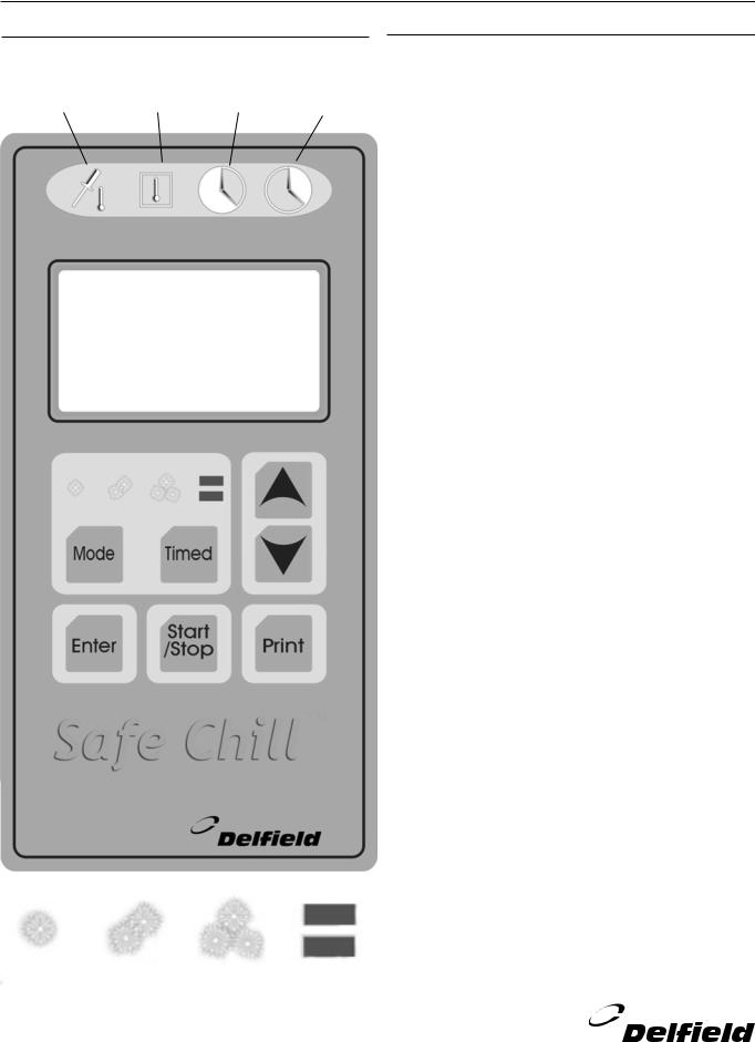
(SEE PAGE 4 FOR DIAGRAM OF CONTROL PANEL)
Operating Pressures
Normal operating pressures should be achieved during the preservation mode, with approximately 75 of ambient
temperature. Freezer mode 15# suction and 220# discharge. Chilling mode 55# suction and 220# discharge.
Blast Chilling (soft mode): This mode pulls the food down from the starting temperature to food set point of 37˚F (FP1). Once the temperature is obtained the unit sounds an alarm and either switches to preservation mode automatically (after the alarm times out) or manually. During pull down in soft mode, the blast chiller maintains a box temperature of 23˚F (BT1). This mode is primarily used for pulling down delicate foods.
Blast Chilling (hard mode): This mode operates the same way as the soft mode except for the box temperature. During pull down from start until one of the two food probes reaches 47˚F (FP2) the box temperature is maintained at -5˚F (BT2), after this point the box temperature is held at 23˚F (BT1) until the food reaches 37˚F (FP1). This mode is for items that are harder to pull down or if a faster chilling time is desired.
Blast Chilling (timed mode): This mode operates in either a soft or hard mode. The user can preset the amount of time the chiller pulls down for up to 240 minutes (TC1). The unit will pull down until the time is reached or the two probes hit 37˚F (FP1). At this point the unit will sound an alarm and go into preservation mode.
Freezer Mode: This mode pulls the food down from starting point to 0˚F (FP3). In this mode the unit operates in a hard chill mode until one of the two food probes reach 37˚F (FP1). At that point the box temperature is pulled down to -25˚F (BT3) until the food set point of 0˚F (FP3) is reached. At this point an alarm is sounded and the unit can go into preservation mode.
Preservation Mode: After any of the above cycles reach their set point, the unit will go into a preservation mode. This mode will be held until the user terminates it. After chilling, the
food probes will maintain a temperature of 37˚F (FP1) using a box temperature of 23˚F (BT1). After the freezing, the food probes will maintain a temperature of 0˚F (FP3) using a box temperature of -15˚F (BT3).
continued pg. 4
For customer service, call (800) 733-8829, (800) 733-8821, Fax (989) 773-3210, www.delfield.com |
3 |

Safe Chill™ Blast Chillers Service & Installation Manual
Safe Chill™ Control |
|
|
|
OPERATION CONTINUED... |
||
Probe |
Box |
Time |
Time |
|
||
Defrost Mode: After chilling/freezing the unit will go into a |
||||||
Temp |
Temp |
Elapsed |
Remaining |
defrost mode for 15 minutes or until the coil reaches a |
||
|
|
|
|
|
|
temperature of 70˚(DF1). During the freezer preservation mode |
|
|
|
|
|
|
the defrost heater will operate for 15 minutes (DF2) or until the |
|
|
|
|
|
|
coil reaches a temperature of 70˚F(DF1) every 6 hours (DF3). |
|
|
|
|
|
|
Tandem Mode (DBC-10 only): In this mode, both the upper |
|
|
|
|
|
|
|
|
|
|
|
|
|
and lower compartments will start at the same time running in |
|
|
|
|
|
|
the same mode of operation (soft, hard, or freezer mode). Once |
|
|
|
|
|
|
operating the compartments cycle independently. For example, |
|
|
|
|
|
|
if the bottom compartment pulls down quicker than the top it will |
|
|
|
|
|
|
shut down without affecting the tops operation. |
|
|
|
|
|
|
Individual Mode (DBC-10 only): This mode allows operation of |
|
|
|
|
|
|
the two compartments in different modes of operation starting |
|
|
|
|
|
|
them at different times. For example, the top compartment can |
|
|
|
|
|
|
be loaded to run in a timed soft chill cycle, and at any time the |
|
|
|
|
|
|
bottom could be loaded in a freezer mode and started. |
|
|
|
|
|
|
Operating the Control |
|
|
|
|
|
|
1. Start Cycle (DBC-10 will start both upper and lower |
|
|
|
|
|
|
units): |
|
|
|
|
|
|
• Press MODE button, display will change. |
|
|
|
|
|
|
• Press MODE button until desired mode (soft, hard, freeze) |
|
|
|
|
|
|
appears in left hand upper corner of display. |
|
|
|
|
|
|
• Press START/STOP button, unit will start cycle. |
|
|
|
|
|
|
2. Start cycle in individual mode (DBC-10 only): |
|
|
|
|
|
|
• Press MODE button, display will change |
|
|
|
|
|
|
• Press MODE button until “Indiv” appears in left hand upper |
|
|
|
|
|
|
corner of display. |
|
|
|
|
|
|
• Press ENTER button. |
|
|
|
|
|
|
• Press MODE button until desired mode (soft, hard, freeze) |
|
|
|
|
|
|
appears in left hand upper corner of display. |
|
|
|
|
|
|
• Press START/STOP button, unit will start cycle. |
|
|
|
|
|
|
3. Start cycle in timed mode (DBC-10 only will start both |
|
|
|
|
|
|
upper and lower units): |
|
|
|
|
|
|
• Press MODE button, display will change |
|
|
|
|
|
|
• Press MODE button until “Indiv” appears in left hand upper |
|
|
|
|
|
|
corner of display. |
|
|
|
|
|
|
• Press TIMED button, counter will appear in right hand |
|
|
|
|
|
|
upper corner of display. |
|
|
|
|
|
|
• Press UP/DOWN buttons to adjust timer to desired setting. |
|
|
|
|
|
|
• Press START/STOP button, unit will start cycle. |
|
|
|
|
|
|
4. To stop a cycle: |
|
|
|
|
|
|
• Press START/STOP button for one second. |
|
|
|
|
|
|
If unit is a DBC-5 or DBC-5U cycle will shut down. |
|
|
|
|
|
|
DBC-10 If only one compartment is running, cycle will shut |
|
|
|
|
|
|
down. If both compartments are running, display will prompt |
|
|
|
|
|
|
you to shut entire unit down by pressing START/STOP |
|
|
|
|
|
|
button. To shut down the individual compartments press |
|
|
|
|
|
|
the UP button for the top or the DOWN button for the |
|
|
|
|
|
|
bottom. |
Soft |
Hard |
Blast |
Dual |
|
||
Chill |
Chill |
Freeze |
Mode |
|
||
4For customer service, call (800) 733-8829, (800) 733-8821, Fax (989) 773-3210, www.delfield.com
 Loading...