


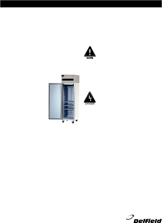
6000XL & 6100XL Series Reach Ins
Service, Installation and Care Manual
Please read this manual completely before attempting to install or operate this equipment! Notify carrier of damage! Inspect all components immediately. See page 2.
Refrigerators and Freezers
IMPORTANT |
INFORMATION |
|||||
|
|
USE |
||||
|
READ |
BEFORE |
|
|||
|
|
|
INSTRUCTIONS! |
|||
|
SAVE |
THESE |
||||
PLEASE |
|
|
||||
|
|
|
|
|
||
|
|
|
|
|
Effective Date May 2004 |
|
|
|
|
|
|
|
|

6000XL Series Service and Installation Manual |
|
CONTENTS |
SERIAL NUMBER INFORMATION |
RECEIVING & INSPECTING EQUIPMENT |
.................................2 |
SPECIFICATIONS........................................................................ |
3 |
INSTALLATION .......................................................................... |
4 |
OPERATION................................................................................ |
5 |
MAINTENANCE ....................................................................... |
6 -7 |
PROGRAMMING GUIDE............................................................ |
8 |
WIRING DIAGRAMS............................................................. |
9 - 10 |
PARTS LISTING .................................................................. |
11 - 14 |
STANDARD LABOR GUIDELINES............................................ |
15 |
STANDARD WARRANTIES ................................................. |
16 - 17 |
AUTHORIZED PARTS DEPOTS................................. |
BACK PAGE |
©2004 The Delfield Company. All rights reserved. Reproduction without written permission is prohibited. “Delfield” is a registered trademark of The Delfield Company.
The serial number of all self-contained 6000XL Series refrigerators and freezers is located above the door under the shroud.
Always have the serial number of your unit available when calling for parts or service. A complete list of authorized Delfield parts depots is shown on the back.
This manual covers standard units only. If you have a custom unit, consult the customer service department at the number listed below.
RECEIVING AND INSPECTING THE EQUIPMENT
Even though most equipment is shipped crated, care should be taken during unloading so the equipment is not damaged while being moved into the building.
1.Visually inspect the exterior of the package and skid or container. Any damage should be noted and reported to the delivering carrier immediately.
2.If damaged, open and inspect the contents with the carrier.
3.In the event that the exterior is not damaged, yet upon opening, there is concealed damage to the equipment notify the carrier. Notification should be made verbally
as well as in written form.
4.Request an inspection by the shipping company of the damaged equipment. This should be done within 10 days from receipt of the equipment.
5.Be certain to check the compressor compartment housing and visually inspect the refrigeration package. Be sure lines are secure and base is still intact.
6.Freight carriers can supply the necessary damage forms upon request.
7.Retain all crating material until an inspection has been made or waived.
2For customer service, call (800) 733-8829, (800) 733-8821, Fax (989) 773-3210, www.delfield.com

6000XL Series Service and Installation Manual
SPECIFICATIONS
6000XL SOLID DOOR REFRIGERATORS
|
|
|
|
STORAGE |
SHELF |
|
|
|
SHIP |
NEMA |
|
|
MODEL # |
VOLTAGE |
AMPS |
CAPACITY FT3 |
CAPACITY FT2 |
H.P. |
BTU |
CHARGE |
WEIGHT |
PLUG |
|
|
6025XL-S |
115 |
12 |
20.0 |
15.1 |
1/3 |
2885 |
11 |
274 LBS |
5-15P |
|
|
6025XL-SH |
115 |
12 |
20.0 |
15.1 |
1/3 |
2885 |
11 |
274 LBS |
5-15P |
|
|
6051XL-S |
115 |
12 |
43.5 |
33.2 |
1/3 |
2981 |
12.5 |
454 LBS |
5-15P |
|
|
6051XL-SH |
115 |
12 |
43.5 |
33.2 |
1/3 |
2981 |
12.5 |
454 LBS |
5-15P |
|
|
6076XL-S |
115 |
13 |
66.5 |
48.3 |
1/2 |
4148 |
13 |
622 LBS |
5-20P |
|
|
6076XL-SH |
115 |
13 |
66.5 |
48.3 |
1/2 |
4321 |
13 |
622 LBS |
5-20P |
|
Remote units supplied with: Evaporator coil, solenoid valve, expansion valve, and temperature control. Condensing units to be sized and supplied by others.
REMOTE |
|
|
STORAGE |
SHELF |
|
|
EVAP |
SHIP |
NEMA |
MODEL # |
VOLTAGE |
AMPS |
CAPACITY FT3 |
CAPACITY FT2 |
H.P.* |
BTU |
TEMP |
WEIGHT |
PLUG |
6025XL-SR |
115 |
5 |
20.0 |
15.1 |
1/3 |
2885 |
20° |
274 LBS |
— |
6025XL-SHR |
115 |
5 |
20.0 |
15.1 |
1/3 |
2885 |
20° |
274 LBS |
— |
6051XL-SR |
115 |
6 |
43.5 |
33.2 |
1/3 |
2981 |
20° |
454 LBS |
— |
6051XL-SHR |
115 |
6 |
43.5 |
33.2 |
1/3 |
2981 |
20° |
454 LBS |
— |
6076XL-SR |
115 |
7 |
66.5 |
48.3 |
1/2 |
4148 |
20° |
622 LBS |
— |
6076XL-SHR |
115 |
7 |
66.5 |
48.3 |
1/2 |
4321 |
20° |
622 LBS |
— |
*Recommended; will vary with refrigerant used, contact factory.
6000XL GLASS DOOR REFRIGERATORS
|
|
|
|
STORAGE |
SHELF |
|
|
|
SHIP |
|
NEMA |
|
|
MODEL # |
VOLTAGE |
AMPS |
CAPACITY FT3 |
CAPACITY FT2 |
H.P. |
BTU |
CHARGE |
WEIGHT |
|
PLUG |
|
|
6025XL-G |
115 |
12 |
20.0 |
15.1 |
1/3 |
1994 |
11 |
338 LBS |
|
5-15P |
|
|
6025XL-GH |
115 |
12 |
20.0 |
15.1 |
1/3 |
1994 |
11 |
338 LBS |
|
5-15P |
|
|
6051XL-G |
115 |
14 |
43.5 |
33.2 |
1/3 |
2453 |
12.5 |
548 LBS |
|
5-20P |
|
|
6051XL-GH |
115 |
14 |
43.5 |
33.2 |
1/3 |
2453 |
12.5 |
548 LBS |
|
5-20P |
|
|
6076XL-G |
115 |
15 |
66.5 |
48.3 |
1/2 |
3057 |
13 |
774 LBS |
|
5-20P |
|
|
6076XL-GH |
115 |
15 |
66.5 |
48.3 |
1/2 |
3057 |
13 |
774 LBS |
|
5-20P |
|
|
Remote units supplied with: Evaporator coil, solenoid valve, expansion valve, and temperature control. Condensing units to be sized and supplied by others. |
|
|
|||||||||
REMOTE |
|
|
STORAGE |
SHELF |
|
|
EVAP |
SHIP |
NEMA |
MODEL # |
VOLTAGE |
AMPS |
CAPACITY FT3 |
CAPACITY FT2 |
H.P.* |
BTU |
TEMP |
WEIGHT |
PLUG |
6025XL-GR |
115 |
5 |
20.0 |
15.1 |
1/3 |
1994 |
20° |
338 LBS |
— |
6025XL-GHR |
115 |
5 |
20.0 |
15.1 |
1/3 |
1994 |
20° |
338 LBS |
— |
6051XL-GR |
115 |
6 |
43.5 |
33.2 |
1/3 |
2453 |
20° |
548 LBS |
— |
6051XL-GHR |
115 |
6 |
43.5 |
33.2 |
1/3 |
2453 |
20° |
548 LBS |
— |
6076XL-GR |
115 |
7 |
66.5 |
48.3 |
1/2 |
3057 |
20° |
774 LBS |
— |
6076XL-GHR |
115 |
7 |
66.5 |
48.3 |
1/2 |
3057 |
20° |
774 LBS |
— |
*Recommended; will vary with refrigerant used, contact factory.
6000XL SOLID DOOR FREEZERS
|
|
|
|
STORAGE |
SHELF |
|
|
|
SHIP |
|
NEMA |
||
|
MODEL # |
VOLTAGE |
AMPS |
CAPACITY FT3 |
CAPACITY FT2 |
H.P. |
BTU |
CHARGE |
WEIGHT |
|
PLUG |
||
|
6125XL-S |
115 |
12 |
20.0 |
15.1 |
1/2 |
1729 |
18 |
274 LBS |
|
5-15P |
|
|
|
6125XL-SH |
115 |
12 |
20.0 |
15.1 |
1/2 |
1729 |
18 |
274 LBS |
|
5-15P |
|
|
|
6151XL-S |
115 |
15 |
43.5 |
33.2 |
3/4 |
3321 |
18.5 |
454 LBS |
|
5-20P |
||
|
6151XL-SH |
115 |
15 |
43.5 |
33.2 |
3/4 |
3321 |
18.5 |
454 LBS |
|
5-20P |
||
|
6176XL-S |
115 |
16 |
66.5 |
48.3 |
3/4 |
3501 |
17 |
622 LBS |
|
5-20P |
||
|
6176XL-SH |
115 |
16 |
66.5 |
48.3 |
3/4 |
3501 |
17 |
622 LBS |
|
5-20P |
|
|
|
Remote units supplied with: Evaporator coil, solenoid valve, expansion valve, and temperature control. Condensing units to be sized and supplied by others. |
|
|
|
|||||||||
REMOTE |
|
|
STORAGE |
SHELF |
|
|
EVAP |
SHIP |
NEMA |
MODEL # |
VOLTAGE |
AMPS |
CAPACITY FT3 |
CAPACITY FT2 |
H.P.* |
BTU |
TEMP |
WEIGHT |
PLUG |
6125XL-SR |
115 |
7 |
20.0 |
15.1 |
1/2 |
1729 |
-15° |
274 LBS |
— |
6125XL-SHR |
115 |
7 |
20.0 |
15.1 |
1/2 |
1729 |
-15° |
274 LBS |
— |
6151XL-SR |
115 |
9 |
43.5 |
33.2 |
3/4 |
3321 |
-15° |
454 LBS |
— |
6151XL-SHR |
115 |
9 |
43.5 |
33.2 |
3/4 |
3321 |
-15° |
454 LBS |
— |
6176XL-SR |
115 |
11 |
66.5 |
48.3 |
3/4 |
3501 |
-15° |
622 LBS |
— |
6176XL-SHR |
115 |
11 |
66.5 |
48.3 |
3/4 |
3501 |
-15° |
622 LBS |
— |
*Recommended; will vary with refrigerant used, contact factory.
For customer service, call (800) 733-8829, (800) 733-8821, Fax (989) 773-3210, www.delfield.com |
3 |
6000XL Series Service and Installation Manual
INSTALLATION
Location
Units represented in this manual are intended for indoor use only. Be sure the location chosen has a floor strong enough to support the total weight of the cabinet and contents. A fully loaded 6000XL series can weigh as much as 1500 pounds. Reinforce the floor as necessary to provide for maximum loading. For the most efficient refrigeration, be sure to provide good air circulation inside and out.
Inside cabinet: Do not pack refrigerator so full that air cannot circulate. The refrigerated air is discharged at the top rear of the unit. It is important to allow for proper air flow from the top rear to the bottom of the unit. Obstructions to this air flow can cause evaporator coil freeze ups and loss of temperature or overflow of water from the evaporator drain pan. The rear of the unit has molded ribs and the shelves have a rear turn up on them to
prevent this. However, bags and other items can still be located to the far rear of the cabinet. There is also a return air diffuser along the top front of the cabinet interior, this also requires proper air circulation. Prevent obstruction by locating large boxes and tall stacks of product
to the bottom of the cabinet. (See Diagram at right)
Outside cabinet: Be sure that the unit has access to ample air. Avoid
hot corners and locations near stoves and ovens.
It is recommended that the unit be installed no closer than 2” from any wall with at least 12” of clear space above the unit. Avoid exposing glass door units to direct sunlight. Direct sunlight through the glass doors will make the ABS liner fade and become brittle and will greatly reduce refrigeration efficiency.
Leveling
A level cabinet looks better and will perform better because the doors will line up with the frames properly, the cabinet will not be subject to undue strain and the contents of the cabinet will not move around on the shelves. Use a level to make sure the unit is level from front to back and side to side. Units supplied with legs will have adjustable bullet feet to make the necessary adjustments. If the unit is supplied with casters, no adjustments are available. Ensure the floor where the unit is to be located is level.
Stabilizing
Some models are supplied on casters for your convenience, ease of cleaning underneath and for mobility. It is very important, however, that the cabinet be installed in a stable condition with the front wheels locked while in use. Should it become necessary to lay the unit on its side or back
for any reason, allow at least 24 hours before start-up so as to allow compressor oil to flow back to the sump. Failure to meet this requirement can cause compressor failure and unit damage.
Unit repairs will not be subject to standard unit warranties due to improper installation procedures.
Electrical connection
Refer to the amperage data on page 3, the serial tag, your local code or the National Electrical Code to be sure the unit is connected to the proper power source. A protected circuit of the correct voltage and amperage must be run for connection of the line cord, or permanent connection to the unit.
The thermostat must be turned to OFF and the unit disconnected from the power source whenever performing service, maintenance functions or cleaning the refrigerated area.
4For customer service, call (800) 733-8829, (800) 733-8821, Fax (989) 773-3210, www.delfield.com

OPERATION
Do not place hot pans on the blue ABS liner. Do not throw items into the storage area. Failure to heed these recommendations could result in damage to the interior of the cabinet.
Temperature control instruction
Refrigerators: A thermostat located at the top of the refrigerator, in the inset portion of the shroud assembly, controls the temperature in the box. The factory setting for the control is “4” and maintains about 38°F (3°C) in the box. Set toward “1” for higher temperatures and toward “7” for lower temperatures.
Freezers: A thermostat located at the top of the freezer, in the inset portion of the shroud assembly, controls the temperature in the box. The factory setting for the control is “4” and maintains about -3°F (-18°C) in the box. Set
toward “1” for higher temperatures and toward “7” for lower temperatures.
Refrigeration cycle
Refrigerators: During the refrigeration cycle the evaporator fans will run continuously with the exception of door openings. The door switch will activate the lights when opened and turn power off to the evaporator fan motors.
1.The temperature control allows for the evaporator coil to clear after each off cycle and before the compressor runs again.
2.Anti-sweat heaters around each door opening operate continually.
Freezers: During the refrigeration cycle the timer supplies power to the temperature control (for power to the condensing unit) and evaporator fan motors. The evaporator fans will run at any time when the evaporator coil temperature is below 35°, they will also cycle off during door openings and during a defrost period. The door switch will activate the lights when opened and turn power off to the evaporator fan motors.
1.See Defrost Cycle
2.Anti-sweat heaters around each door opening operate continually.
Defrost cycle - Freezers only
When defrost control goes into defrost, power to the condensing unit and evaporator fans is interrupted and the defrost heater is energized. The defrost heater warms the evaporator coil thereby melting all frost accumulated during the previous refrigeration cycle. Once all frost is eliminated, the temperature of the coil continues to rise until it reaches 70°F (27°C). When this temperature is sensed by the defrost limit control, the defrost control switches to refrigeration mode.
6000XL Series Service and Installation Manual
If for any reason the timer remains in defrost for a period of time greater than 40 minutes, a back-up defrost termination is also provided which will terminate defrost at 80°F.
The defrost time can be changed in the field as follows: On two and three door models push down and rotate pointer on inside (2 hour) dial until it is opposite desired time period (in minutes). On 1 door models, it can be changed by adjusting the electric control switches 1 thru 4, “Defrost Time” as shown on page 8 figure 1.
Freezer defrost control: All 6151XL-S & 6176XL-S freezers are equipped with a Paragon 8145 defrost control for automatic defrosting of the evaporator coil. All 6125XL-S freezers are equipped with Air-O-Tronics time clock for automatic defrosting of the evaporator coil. Air-O-Tronics can not be adjusted to the time of day.
To set time of day (Two & three door models only): Grasp the knob of the Paragon 8145 time clock dial in the center of the inner (2 hour) dial and rotate it in a counter-clockwise direction (see page 8 figure 2). This will revolve the outer dial. Continue turning until the correct time of day on the outer dial lines up with the time pointer. This operation requires an initial start-up and any time thereafter when there is an interruption of power to the freezer.
NOTE: There is no time adjustment for one door models.
Operation (One door models): The electric defrost controller is preset at the factory to provide a defrost cycle every 6 hours (4 defrosts per day). If it is necessary to change the number of defrosts due to unusual operating conditions,
it can be accomplished by adjusting switches 1 thru 4 on “Cycletime” dip switches.
Operation (Two & three door models): The Paragon 8145 timer is preset at the factory to provide four defrosts per day at six hour intervals starting at 6:00 am. If it is necessary to change the number of defrosts due to unusual operating conditions it can be accomplished by placing the pins in the outer dial at the appropriate time of the day that defrost initiation is desired.
Even under the most severe operating conditions it should not be necessary to set the back-up time greater than 60 minutes. Consult the factory if complete de-icing of the coil is not accomplished within this time period.
For customer service, call (800) 733-8829, (800) 733-8821, Fax (989) 773-3210, www.delfield.com |
5 |
6000XL Series Service and Installation Manual
MAINTENANCE
The thermostat must be turned to OFF and the unit disconnected from the power source whenever performing service, maintenance functions or cleaning the refrigerated area.
Refrigerators and Freezers
The interior and exterior can be cleaned using soap and warm water. If this isn’t sufficient, try ammonia and water or a nonabrasive liquid cleaner. When cleaning the exterior, always rub with the “grain” of the stainless steel to avoid marring the finish.
Do not use an abrasive cleaner because it will scratch the stainless steel and plastic and can damage the breaker strips and gaskets.
Cleaning the Condenser Coil
The condenser coil requires regular cleaning, recommended is every 90 days. In some instances though you may find that there is a large amount of debris and dust or grease accumulated prior to the 90 day time frame. In these cases the condenser coil should be cleaned every 30 days.
If the build up on the coil consists of only light dust and debris the condenser coil can be cleaned with a simple brush, heavier dust build up may require a vacuum or even compressed air to blow through the condenser coil.
If heavy grease is present there are de-greasing agents available for refrigeration use and specifically for the condenser coils. The condenser coil may require a spray with the degreasing agent and then blown through with compressed air.
Failure to maintain a clean condenser coil can initially cause high temperatures and excessive run times, continuous operation with dirty or clogged condenser coils can result in compressor failures. Neglecting the condenser coil cleaning procedures will void any warranties associated with the compressor or cost to replace the compressor.
Never use a high pressure water wash for this cleaning procedure as water can damage the electrical components located near or at the condenser coil.
In order to maintain proper refrigeration performance, the condenser fins must be cleaned of dust, dirt and grease regularly. It is recommended that this be done at least every three months. If conditions are such that the condenser is totally blocked in three months, the frequency of cleaning should be increased. Clean the condenser with a vacuum cleaner or stiff brush. If extremely dirty, a commercially available condenser cleaner may be required.
Stainless Steel Care and Cleaning
To prevent discoloration of rust on stainless steel several important steps need to be taken. First, we need to understand the properties of stainless steel. Stainless steel contains 7080% iron which will rust. It also contains 12-30% chromium which forms an invisible passive film over the steels surface which acts as a shield against corrosion. As long as the protective layer is intact, the metal is still stainless. If the film is broken or contaminated, outside elements can begin to breakdown the steel and begin to form rust of discoloration.
Proper cleaning of stainless steel requires soft cloths or plastic scouring pads.
NEVER USE STEEL PADS, WIRE BRUSHES OR
SCRAPERS!
Cleaning solutions need to be alkaline based or non-chloride cleaners. Any cleaner containing chlorides will damage the protective film of the stainless steel. Chlorides are also commonly found in hard water, salts, and household and industrial cleaners. If cleaners containing chlorides are used be sure to rinse repeatedly and dry thoroughly upon completion.
Routine cleaning of stainless steel can be done with soap and water. Extreme stains or grease should be cleaned with a non-abrasive cleaner and plastic scrub pad. It is always good to rub with the grain of the steel. There are also stainless steel cleaners available which can restore and preserve the finish of the steels protective layer.
Early signs of stainless steel breakdown can consist of small pits and cracks. If this has begun, clean thoroughly and start to apply stainless steel cleaners in attempt to restore the passivity of the steel.
Never use an acid based cleaning solution! Many food products have an acidic content which can deteriorate the finish. Be sure to clean the stainless steel surfaces of ALL food products. Common items include, tomatoes, peppers and other vegetables.
6For customer service, call (800) 733-8829, (800) 733-8821, Fax (989) 773-3210, www.delfield.com
 Loading...