


™
 DELFIELD®
EXCELeration™ Systems
Service and Installation Manual
Please read this manual completely before attempting to install or operate this equipment! Notify carrier of damage! Inspect all components immediately. See page 2.
Sandwich and Pizza Production Centers
|
|
|
|
INFORMATION |
||
IMPORTANT |
|
|
USE |
|||
|
READ |
BEFORE |
|
|||
|
|
|
INSTRUCTIONS! |
|||
|
SAVE |
THESE |
||||
|
|
|
||||
PLEASE |
|
|
|
|
|
|
|
|
|
|
|
|
|
July 2010

EXCELeration™ Series Service and Installation Manual
Contents |
|
Serial Number Location ........................................................ |
2 |
Receiving & Inspecting ......................................................... |
2 |
Specifications........................................................................ |
3 |
Installation ............................................................................ |
3 |
Operation .............................................................................. |
4 |
Pressure Control Settings ..................................................... |
4 |
Maintenance...................................................................... |
5-6 |
Wiring Diagrams ................................................................... |
7 |
Condensing Unit Assembly ................................................... |
8 |
Evaporator Assembly ............................................................ |
8 |
Door Assembly ..................................................................... |
9 |
Drawer Assembly.................................................................. |
9 |
Replacement Parts.............................................................. |
10 |
Replacement Part Prints ..................................................... |
11 |
Standard Labor Guidelines.................................................. |
12 |
Warranties..................................................................... |
13-14 |
Notes .................................................................................. |
15 |
Serial Number Location
The serial number on all EXCELeration™ systems is located on the electrical specifications tag affixed inside the compressor section next to the pressure control.
Always have the serial number of your unit available when calling for parts or service. A complete list of authorized Delfield parts depots can be found at www.delfield.com.
©2010 The Delield Company. All rights reserved. Reproduction without written permission is prohibited. “Delield” is a registered trademark of The Delield Company.
Refer to the Lincoln 1300 Series Conveyor Oven manual for operation, maintenance and service instructions. Refer to the Lincoln Fusion Conveyor Toaster manual for operation, maintenance and service instructions. Refer to the Merco MHC Holding Cabinet manual for operation, maintenance and service instructions.
Lincoln/Merco Telephone number (260) 459-8200 Service Hotline is (800) 678-9511
Receiving and Inspecting the Equipment
Even though most equipment is shipped crated, care should be taken during unloading so the equipment is not damaged while being moved into the building.
1.Visually inspect the exterior of the package an skid or container. Any damage should be noted and reported to the delivering carrier immediately.
2.If damaged, open and inspect the contents with the carrier.
3.In the event that the exterior is not damaged, yet upon opening, there is concealed damage to the equipment notify the carrier. Notification should be made verbally as well as in written form.
4.Request an inspection of the concealed equipment. This should be done within 10 days from receipt of the equipment.
5.Check the lower portion of the unit to be sure legs or casters are not bent.
6.Also open the compressor compartment housing and visually inspect the refrigeration package. Be sure lines are secure and base is still intact.
7.Freight carriers can supply the necessary forms upon request.
8.Retain all crating material until an inspection has been made or waived.
Uncrating the Equipment
First cut and remove the banding from around the crate. Remove the front of the crate material, use of some tools will be required. If the unit is on legs remove the top of the crate as well and lift the unit off the skid. If the unit is on casters it can be "rolled" off the skid.
2For customer service, call (800) 733-8829, (800) 773-8821, Fax (989) 773-3210, www.delfield.com
EXCELeration™ Series Service and Installation Manual
Specifications
Custom Model |
Total Base |
# Of Doors |
Shelf Area |
# Of Drawers |
# Of Pans in |
H.P, |
V/Hz/Ph |
Amps |
NEMA |
Ship |
|
Storage FT3 |
|
FT2 |
|
Drawers |
|
|
|
Plug |
Weight |
Sandwich Production Systems |
|
|
|
|
|
|
|
|
|
|
|
|
|
|
|
|
|
|
|
|
|
F18RC86-ES2L |
14.01 |
(1) 24” |
3.40 |
(2) 27" |
(4) 12"x20" |
1/3 |
120/208/60/1 |
36.0 |
14-50 |
920lbs |
F18RC86-ES2R |
|
|
|
|
|
|
|
|
|
(417kg) |
|
|
|
|
|
|
|
|
|
|
|
|
|
|
|
|
|
|
|
|
|
|
Pizza Production Systems |
|
|
|
|
|
|
|
|
|
|
|
|
|
|
|
|
|
|
|
|
|
F18RC119-ES1L |
14.01 |
(1) 24” |
3.40 |
(2) 27" |
(4) 12"x20" |
1/3 |
120/208/60/1 |
41.0 |
14-60 |
980lbs |
F18RC119-ES1R |
|
|
|
|
|
|
|
|
|
(445kg) |
|
|
|
|
|
|
|
|
|
|
|
Installation
Location
These units are intended for indoor use only. Be sure the location chosen has a floor strong enough to support the total weight of the cabinet and contents. A fully loaded model may weigh as much as 1500 pounds! Reinforce the floor as necessary to provide for maximum loading.
It is very important to allow for proper air flow, both inside and outside.
Avoid hot corners and locations near stoves, ovens and other pieces of cooking equipment.
It is recommended that the unit be installed no closer than 1” from any wall. Do not install the unit near any combustible material or object affected by heat or moisture.
Leveling
A level cabinet looks better and will perform better because the drain pan will drain properly, the doors will line up with the frames properly, and the cabinet will not be subject to undue strain.
A unit on legs will have an adjustable bullet foot on each leg, adjust each for a level unit. A unit on casters will not be adjustable. Be sure the unit is on a level floor, make necessary changes to the floor for proper level.
Lock all front casters to ensure the stability of the unit.
Plumbing
Models are standard with a condensate evaporator. If, for some reason a unit does not have a condensate evaporator, or if the evaporator fails, the unit’s drain must have an outlet to an appropriate drainage area or container. A refrigerated rail will
have a 1" drain which will need to be run to an appropriate floor drain or container. The drain will be stubbed to the bottom of the machine compartment. Either run drain to a floor drain or add a valve to the base of the machine compartment and drain the rail to a container when convenient.
Moisture collecting from improper drainage can create a slippery surface on the floor and a hazard to employees. It is the owner’s responsibility to
CAUTION provide a container or outlet for drainage.
Electrical connection
Refer to the amperage data on pages 3, the serial tag, your local code or the National Electrical Code to be sure the unit is connected to the proper power source. A protected circuit of the correct voltage and amperage must be run for connection of the line cord, or permanent connection of the unit.
An ON/OFF switch is located directly behind the louvered panel covering the compressor section. Simply turn the switch to ON to begin operation.
The power switch must be turned to OFF and the unit disconnected from the power source whenever performing service or maintenance functions.
Never operate the unit without the louvered panel in place!
If electrical receptacles are to be mounted in the unit’s backsplash, they must be wired independently from the existing unit wiring.
For customer service, call (800) 733-8829, (800) 773-8821, Fax (989) 773-3210, www.delfield.com |
3 |
EXCELeration™ Series Service and Installation Manual
Operation
After turning the ON/OFF switch to ON the unit’s compressor will begin operating. Delfield refrigerated bases are designed to maintain an operational temperature of 36°F to 40°F. Temperature in the refrigerated rail opening is 33°F to 41°F with pans recessed 3” on a standard wrapped refrigerated rail at 86°F ambient room temperature.
Do not place hot pans on/against the blue ABS liner. Do not throw items into the storage area. Failure to heed these recommendations could result in damage to the interior of the cabinet or to the blower coil.
Overloading the storage area, restricting the air flow, and continuous opening and closing of the doors and drawers will hamper the units ability to maintain operational temperature.
Refrigerated Rail
Product in the rail should be removed to the refrigerated base at the end of the day. A rail on/off switch is provided and is required to be shut off at night. The rail switch shuts off the rail only. This allows you to to save energy and the rail will have time to defrost as needed. It also helps maintain product quality. Standard wrapped refrigerated units are controlled by the pressure control which is set to maintain the proper rail temperature. To ensure product quality in the rail it is recommended that product be rotated every four hours.
If adding any item to the unit, be sure to keep in mind the location of the refrigeration lines on wrapped rail units. A refrigeration leak in a rail is extremely difficult and costly to repair. In some cases it cannot be repaired at all.
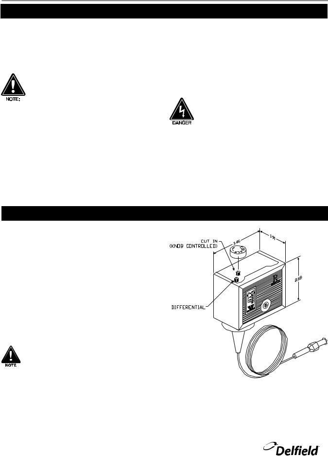
Pressure Control Settings
The factory recommended low-pressure control settings are: 55psi (3.79bar) cut-in and 30psi (2.07bar) cut-out to maintain proper temperature for product in the rail. The interior temperature is controlled by the thermostat mounted on the evaporator coil housing.
Pressure Control
The temperature is controlled by an adjustable pressure control located in the machine compartment. An adjustable control has the word COLDER near the knob, with an arrow to indicate the adjustment direction. These controls are field adjustable and do not require a service agent. If you have any questions, feel free to contact the Delfield Service Department.
In attempting to adjust the pressure control, you can do damage to your unit by accidentally adjusting the differential. Please make small incremental adjustments if a temperature adjustment is necessary, please contact the service department at Delfield (800) 733-8829 or your local service agent. Delfield is not responsible for charges incurred while having the pressure control adjusted.
4For customer service, call (800) 733-8829, (800) 773-8821, Fax (989) 773-3210, www.delfield.com
EXCELeration™ Series Service and Installation Manual
Maintenance
Door Gasket Maintenance
Door gaskets require regular cleaning to prevent mold and mildew build up and also to retain the elasticity of the gasket. Gasket cleaning can be done with the use of warm soapy water. Avoid full strength cleaning products on gaskets as this can cause them to become brittle and crack. Never use sharp tools or knives to scrape or clean the gasket. Gaskets can be easily replaced and do not require the use of tools or an authorized service person. The gaskets are “Dart” style and can be pulled out of the groove in the door and new gaskets can be “pressed” back into place.
Drain Maintenance - Base
Each unit has a drain located inside the unit that removes the condensation from the evaporator coil and routes it to an external condensate evaporator pan. Each drain can become loose or disconnected during normal use. If you notice water accumulation on the inside of the unit be sure the drain tube is connected to the evaporator drain pan. If water is collecting underneath the unit make sure the end of the drain tube is in the condensate evaporator in the machine compartment. The leveling of the unit is important as the units are designed to drain properly when level. Be sure all drain lines are free of obstructions.
Drawer Maintenance
Drawer Assembly Cleaning
The drawer assembly is designed to be cleaned easily. Both drawer and tracks are removable without tools. The drawer tracks are dishwasher safe or can be cleaned in a sink with detergents and a soft bristle brush. Drawers and tracks should be cleaned on a weekly basis.
Remove Drawers
Pull the drawer box out until it stops. Lift up on the drawer front and pull the drawer box completely out. Using a soft bristle brush, clean the track on the bottom of the drawer box. When inished, it should be wiped clean of all food and debris.
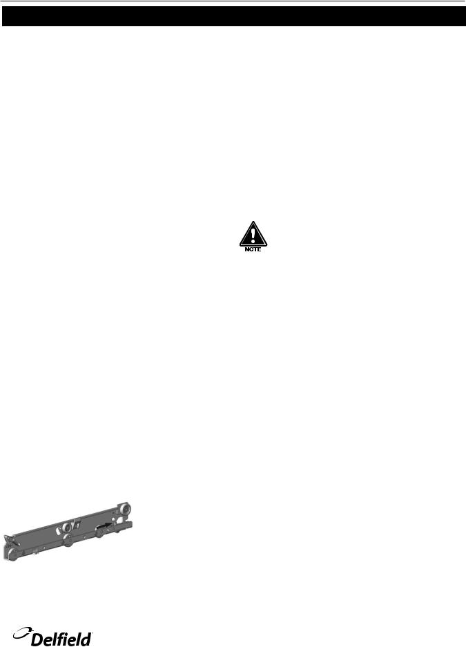
Tracks
The drawer box assembly must be removed. Pull the drawer tracks out until they hit a stop. Locate blue safety clips towards the back of each drawer track. Blue safety clips have a tab on the top. Push the tab back until it clicks. Lift up and pull the drawer tracks all the way out of the drawer cage.
The drawer tracks are dishwasher safe or can be cleaned in a sink with detergents and a soft bristle brush. Drawers
and tracks should be cleaned on a weekly basis. Using a soft bristle brush, wash the track making sure each roller is thoroughly cleaned. The drawer cage should be cleaned with a soft bristle brush, removing any food and debris gathered
on the bottom ledge. Once it’s cleaned thoroughly with a soft bristle brush, wipe remaining debris clean with a soft towel. Reassembly
Push the drawer tracks into the drawer cage. The blue safety clip must remain pushed towards the back. Lift up and slide the drawer track all the way into the drawer cage. The blue safety clip will lock in place automatically. Once all tracks are replaced, insert the drawer box. Rest the drawer box bottom track on the front track roller. Then push the drawer back in place SLOWLY. When the drawer box is about half way in you will hit a STOP. You must lift the front of the drawer up approximately ½” (1.3cm) to continue inward. Clean tracks as often as possible. The cleaner the tracks are the better they will operate.
Caster Maintenance
Wipe casters with a damp cloth monthly to prevent corrosion.
The power switch must be turned to OFF and the unit disconnected from the power source whenever performing service, maintenance functions or cleaning the refrigerated area.
Refrigerators and Freezers
The interior and exterior can be cleaned using soap and warm water. If this isn’t suficient, try ammonia and water or a nonabrasive liquid cleaner. When cleaning the exterior, always rub with the “grain” of the stainless steel to avoid marring the inish. Do not use an abrasive cleaner because it will scratch the stainless steel and can damage the breaker strips and gaskets.
Stainless Steel Care and Cleaning
To prevent discoloration or rust on stainless steel several important steps need to be taken. First, we need to understand the properties of stainless steel. Stainless steel contains 7080% iron, which will rust. It also contains 12-30% chromium, which forms an invisible passive ilm over the steel’s surface, which acts as a shield against corrosion. As long as the protective layer is intact, the metal is still stainless. If the ilm is broken or contaminated, outside elements can begin to breakdown the steel and begin to form discoloration or rust. Proper cleaning of stainless steel requires soft cloths or plastic scouring pads.
NEVER USE STEEL PADS, WIRE BRUSHES OR SCRAPERS!
Cleaning solutions need to be alkaline based or non-chloride cleaners. Any cleaner containing chlorides will damage the protective ilm of the stainless steel. Chlorides are also commonly found in hard water, salts, and household and industrial cleaners. If cleaners containing chlorides are used be sure to rinse repeatedly and dry thoroughly. Routine cleaning of stainless steel can be done with soap and water. Extreme stains or grease should be cleaned with a non-abrasive cleaner and plastic scrub pad. Always rub with the grain of the steel.
For customer service, call (800) 733-8829, (800) 773-8821, Fax (989) 773-3210, www.delfield.com |
5 |
 Loading...