


KCSC
Delfield KCSC, KHCR, KC, F KCFM, SCSC Service Manual
...
Shelleyglas
®
/Shelleysteel
®
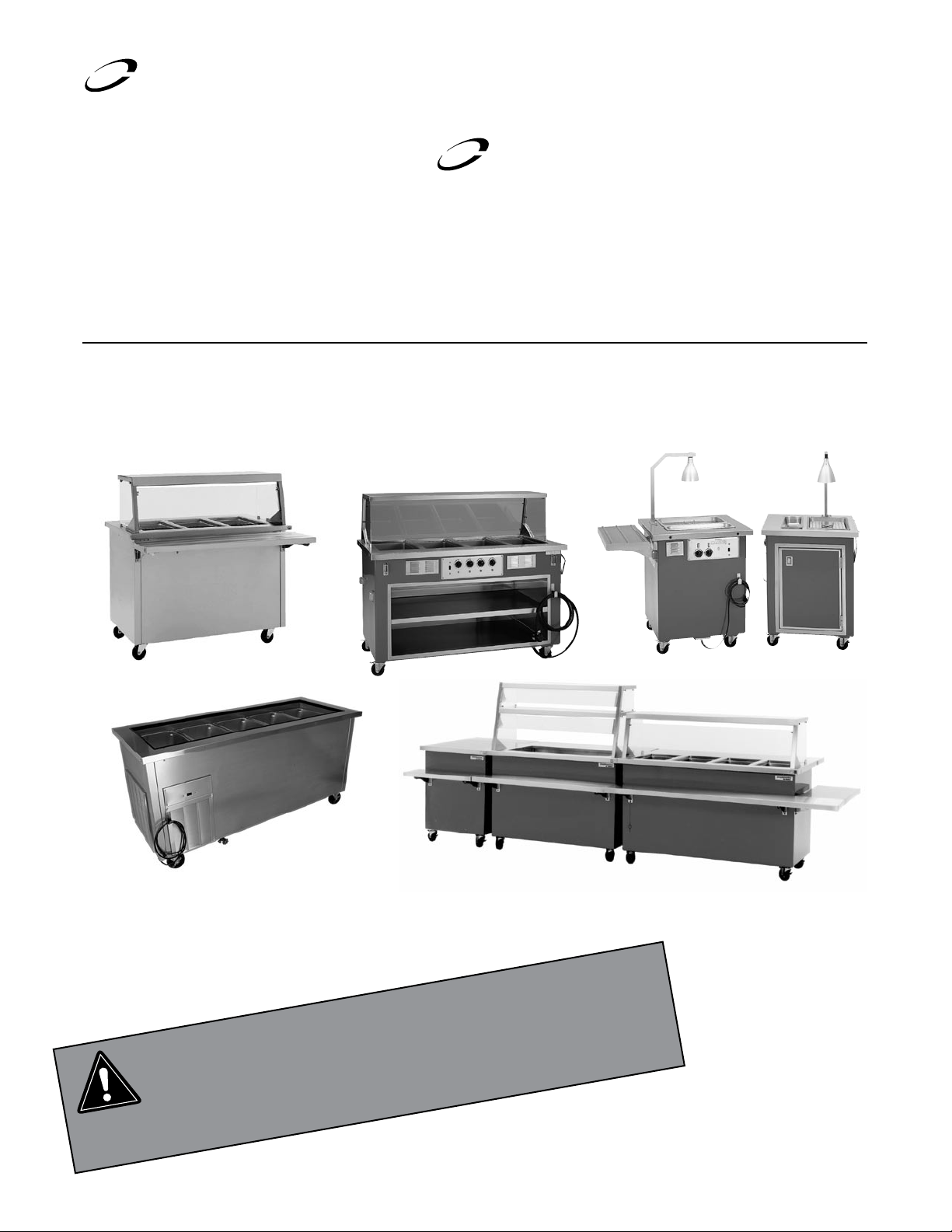
Service and Installation Manual
Please read this manual completely before attempting to install or operate this equipment!
Notify carrier of damage! Inspect all components immediately. See page 2.
Refrigerated, Heated and Non-Electrical Units
Shelleysteel
®
by Delfield
Shelleyglas
®
by Delfield
September 2010
IMPORTANT INFORMATION
READ BEFORE USE
PLEASE SAVE THESE INSTRUCTIONS!
CAUTION
Shelleyglas
®
/Shelleysteel™ Service and Installation Manual
For customer service, call (800) 733-8829, (800) 773-8821, Fax (989) 773-3210, www.delfield.com
2
If your unit is heated, the serial tag is located above the louvered
panel near the on/off switch.
Refrigerated units have the serial tag located in the compressor
area near the on/off switch.
Understorage units often have the serial tag located on the left
inside the storage area.
All purpose counters, utility equipment or delivery carts do
not require serial numbers but a model tag is placed at the top
of the pylon on the back of the unit.
Always have the serial number of your unit available when
calling for parts or service.
This manual covers standard units only. If you have a custom
unit, consult the customer service department at the number
listed below.
©2010 The Delfield Company. All rights reserved. Reproduction without
written permission is prohibited. “Delfield” is a registered trademarks of The
Delfield Company.
Contents Serial Number Information
Receiving And Inspecting The Equipment
Even though most equipment is shipped crated, care should
be taken during unloading so the equipment is not damaged
while being moved into the building.
1. Visually inspect the exterior of the package and skid or
container. Any damage should be noted and reported to
the delivering carrier immediately.
2. If damaged, open and inspect the contents with the
carrier.
3. In the event that the exterior is not damaged, yet upon
opening, there is concealed damage to the equipment
notify the carrier. Notification should be made verbally
as well as in written form.
4. Request an inspection by the shipping company of the
damaged equipment. This should be done within 10
days from receipt of the equipment.
5. Check the lower portion of the unit to be sure legs or
casters are not bent.
6. Also open the compressor compartment housing and
visually inspect the refrigeration package. Be sure lines
are secure and base is still intact.
7. Freight carriers can supply the necessary damage forms
upon request.
8. Retain all crating material until an inspection has been
made or waived.
The units with LiquiTec technology cold pans contain
a non-toxic eutectic fluid within a sealed inner liner.
This fluid may leak if the tank is punctured so care
must be taken when uncrating and setting in place.
The eutectic fluid is non-toxic and may be flushed
down a disposal drain. If the LiquiTec unit cold pans
leak, immediately call the Delfield service department
directly at 1-800-733-8821 not your local service
agent.
Uncrating the Equipment
First cut and remove the banding from around the crate.
Remove the front of the crate material, use of some tools will
be required. If the unit is on legs remove the top of the crate
as well and lift the unit off the skid. If the unit is on casters it
can be "rolled" off the skid.
Receiving & Inspecting Equipment ...........................................2
Shelleyglas Specifications .......................................................3-4
Shelleysteel Specifications ......................................................5-6
Installation: Heated Units ..........................................................7
Operation: Heated Units .............................................................7
Installation: Refrigerated Units ..................................................8
Operation: LiquiTec Units ...........................................................8
Pressure Control Settings ..........................................................9
Maintenance ........................................................................10-11
Food Well Assembly.................................................................12
Wiring Diagrams .................................................................13-16
Replacement Parts List .......................................................17-18
Exploded Views & Replacement Parts ....................................19
Standard Labor Guidelines ......................................................20
Standard Warranties ...........................................................21-22
Notes ........................................................................................23
Shelleyglas
®
/Shelleysteel™ Service and Installation Manual
3
For customer service, call (800) 733-8829, (800) 773-8821, Fax (989) 773-3210, www.delfield.com
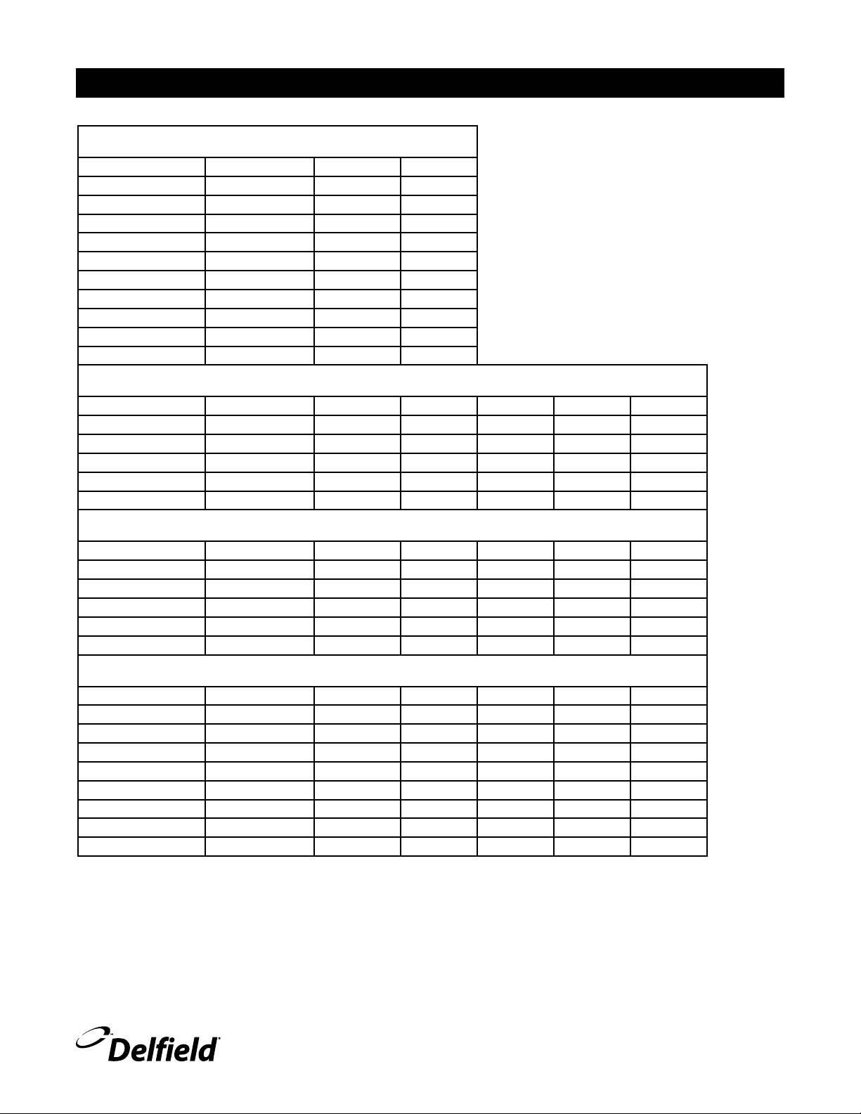
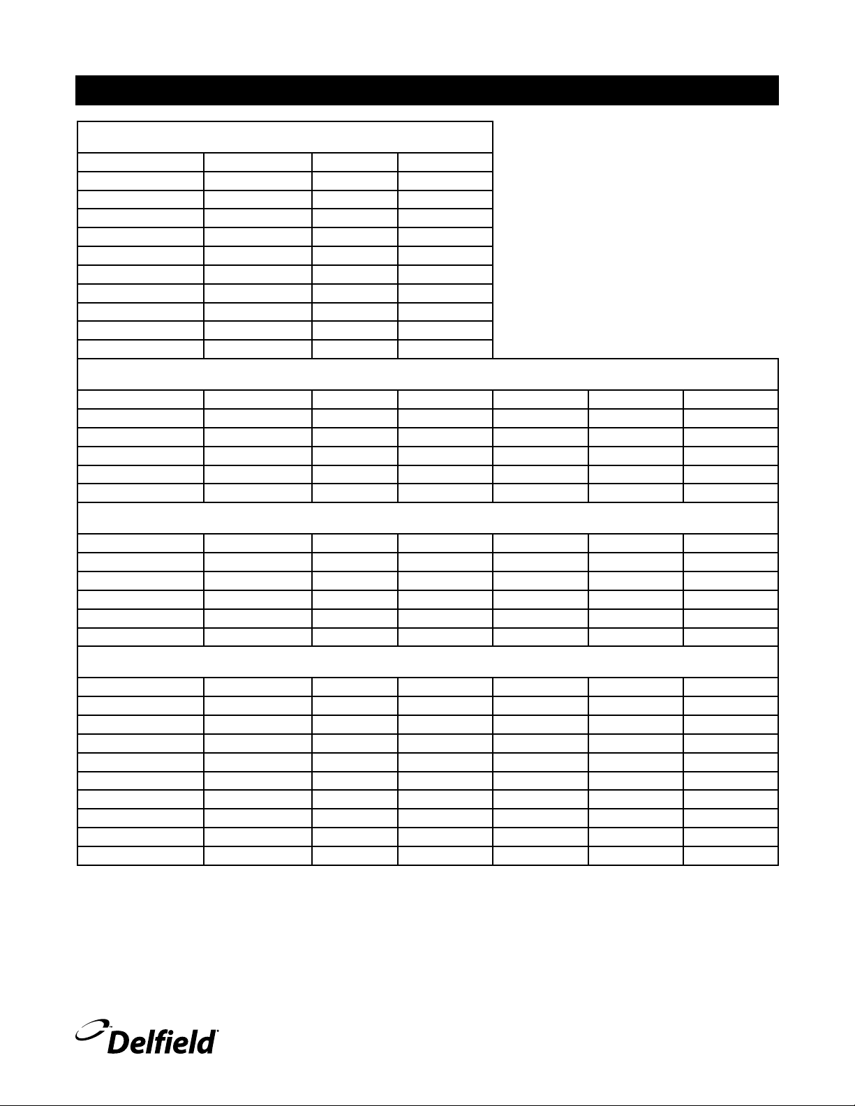
Shelleyglas® Specifications
Heated Serving Counters
Model V/ Hz/Ph NEMA Plug Amperage
KH-2 120/208-230/60/1 14-20P 15.0
KH-3 120/208-230/60/1 14-30P
20.0
KH-4 120/208-230/60/1 14-50P 26.0
KH-5 120/208-230/60/1 14-50P 31.0
KH-6 120/208-230/60/1 14-50P 37.0
KH-2-NU 120/208-230/60/1 14-20P 11.0
KH-3-NU 120/208-230/60/1
14-20P 16.0
KH-4-NU 120/208-230/60/1 14-30P 22.0
KH-5-NU 120/208-230/60/1 14-50P 28.0
KH-6-NU 120/208-230/60/1 14-50P 33.0
Refrigerated Cold Pan Serving Counters
Model V/ Hz/Ph NEMA Plug Amperage H.P. Refrigerant BTU
KCSC-36B 115/60/1 5-15P 7.0 1/4 404a 1102
KCSC-50B 115/60/1 5-15P 7.0 1/4 404a 1240
KCSC-60B 115/60/1 5-15P 7.0 1/4 404a 1343
KCSC-74B 115/60/1 5-15P 7.0 1/4 404a 1423
KCSC-96B 115/60/1 5-15P 7.0 1/4 404a 1487
Shelleyglas with LiquiTec
Model V/ Hz/Ph NEMA Plug Amperage H.P. Refrigerant BTU
KCSC-36-EF 115/60/1 5-15P 7.0 1/4 404a 1102
KCSC-50-EF 115/60/1 5-15P 7.0 1/4 404a 1240
KCSC-60-EF 115/60/1 5-15P 7.0 1/4 404a 1343
KCSC-74-EF 115/60/1 5-15P 7.0 1/4 404a 1423
KCSC-96-EF 115/60/1 5-15P 7.0 1/4 404a 1487
Heated and Refrigerated Combo Counters
Model V/ Hz/Ph NEMA Plug Amperage H.P. Refrigerant BTU
KHCR-50-B 120/60/1 5-20P 16.0 1/4 404a 1102
KHCR-60-B 120/60/1 5-20P 16.0 1/4 404a 1102
KHCR-74-B 120/60/1 5-20P 16.0 1/4 404a 1102
KHCR-96-B 120/60/1 5-20P 16.0 1/4 404a 1240
KH2CR-72-B 120/208-230/60/1 14-30P 18.0 1/4 404a 1102
KH2CR-96-B 120/208-230/60/1 14-30P 18.0 1/4 404a 1343
KH3CR-96-B 120/208-230/60/1 14-30P 23.0
1/4 404a 1240
KH4CR-96-B 120/208-230/60/1 14-50P 29.0 1/4 404a 1102
This manual covers standard units only. If you have a custom unit, consult the customer service department at the number listed below.
Shelleyglas
®
/Shelleysteel™ Service and Installation Manual
For customer service, call (800) 733-8829, (800) 773-8821, Fax (989) 773-3210, www.delfield.com
4
Heated and Ice Cooled Combo Counters
Model V/ Hz/Ph NEMA Plug Amperage
KHC-50-NU 120/60/1 5-15P 9.0
KHC-60-NU 120/60/1 5-15P 9.0
KHC-74-NU 120/60/1 5-15P 9.0
KHC-96-NU 120/60/1 5-15P 9.0
KH2C-74-NU 120/208-230/60/1 14-20P 11.0
KH2C-96-NU 120/208-230/60/1 14-20P 11.0
KH3C-74-NU 120/208-230/60/1
14-20P 16.0
KH3C-96-NU 120/208-230/60/1
14-20P 16.0
KH4C-96-NU 120/208-230/60/1 14-30P 22.0
Frost Top Serving Counters
Model V/ Hz/Ph NEMA Plug Amperage H.P. Refrigerant BTU
KCFT-36-NU 115/60/1 5-15P 7.0 1/4 404a 435
KCFT-50-NU 115/60/1 5-15P 7.0 1/4 404a 595
KCFT-60-NU 115/60/1 5-15P 7.0 1/4 404a 717
KCFT-74-NU 115/60/1 5-15P 7.0 1/4 404a 827
KCFT-96-NU 115/60/1 5-15P 7.0 1/4 404a 921
Milk Counters
Model V/ Hz/Ph NEMA Plug Amperage H.P. Refrigerant BTU
KCM-36 115/60/1 5-15P 7.0 1/4 404A 1114
KCM-50 115/60/1 5-15P 7.0 1/4 404A 1190
KCM-60 115/60/1 5-15P 7.0 1/4 404A 1329
KCM-74 115/60/1 5-15P 7.0 1/4 404A 1535
Ice Cream Counters
Model V/ Hz/Ph NEMA Plug Amperage H.P. Refrigerant BTU
KCF-36 115/60/1 5-15P 7.0 1/4 404A 915
KCF-50 115/60/1 5-15P 7.0 1/4 404A 1350
KCF-60 115/60/1 5-15P 8.0 1/3 404A 1456
KCF-74 115/60/1 5-15P 8.0 1/3 404A 1609
Milk and Ice Cream Counters
Model V/ Hz/Ph NEMA Plug Amperage H.P. Refrigerant BTU
REF/FRZ
KCFM-50 115/60/1 5-15P 7.0 1/4 404A 789/1580
KCFM-74 115/60/1 5-15P 8.0 1/3 404A 1199/2040
Carving Counter
Model V/ Hz/Ph NEMA Plug Amperage
KRB 115/60/1 5-15P 5.0
Shelleyglas® Specifications, continued
Shelleyglas
®
/Shelleysteel™ Service and Installation Manual
5
For customer service, call (800) 733-8829, (800) 773-8821, Fax (989) 773-3210, www.delfield.com
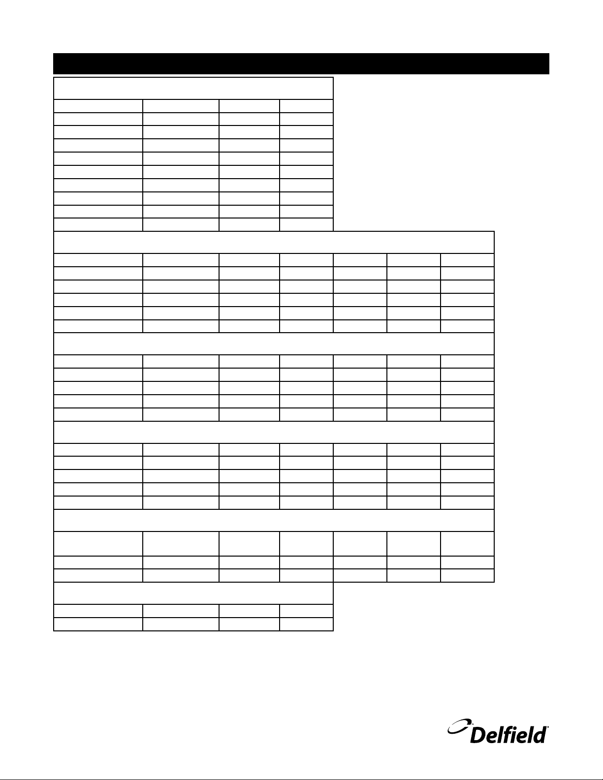
Heated Serving Counters
Model V/Hz/Ph NEMA Plug Amperage
SH-2 120/208-230/60/1 14-20P 15.0
SH-3 120/208-230/60/1 14-30P
20.0
SH-4 120/208-230/60/1 14-50P 26.0
SH-5 120/208-230/60/1 14-50P 31.0
SH-6 120/208-230/60/1 14-50P 37.0
SH-2-NU 120/208-230/60/1 14-20P 11.0
SH-3-NU 120/208-230/60/1
14-20P 16.0
SH-4-NU 120/208-230/60/1 14-30P 22.0
SH-5-NU 120/208-230/60/1 14-50P 28.0
SH-6-NU 120/208-230/60/1 14-50P 33.0
Refrigerated Cold Pan Serving Counters
Model V/Hz/Ph NEMA Plug Amperage H.P. Refrigerant BTU
SCSC-36B
115/60/1 5-15P 7.0 1/4 404a 1102
SCSC-50B 115/60/1 5-15P 7.0 1/4 404a 1240
SCSC-60B 115/60/1 5-15P 7.0 1/4 404a 1343
SCSC-74B 115/60/1 5-15P 7.0 1/4 404a 1423
SCSC-96B 115/60/1 5-15P 7.0 1/4 404a 1487
Shelleysteel with LiquiTec
Model V/Hz/Ph NEMA Plug Amperage H.P. Refrigerant BTU
SCSC-36-EF
115/60/1 5-15P 7.0 1/4 404a 1102
SCSC-50-EF 115/60/1 5-15P 7.0 1/4 404a 1240
SCSC-60-EF 115/60/1 5-15P 7.0 1/4 404a 1343
SCSC-74-EF 115/60/1 5-15P 7.0 1/4 404a 1423
SCSC-96-EF 115/60/1 5-15P 7.0 1/4 404a 1487
Heated and Refrigerated Combo Counters
Model V/Hz/Ph NEMA Plug Amperage H.P. Refrigerant BTU
SHCR-50-B 120/60/1 5-20P 16.0 1/4 404a 1102
SHCR-60-B 120/60/1 5-20P 16.0 1/4 404a 1102
SHCR-74-B 120/60/1 5-20P 16.0 1/4 404a 1102
SHCR-96-B 120/60/1 5-20P 16.0 1/4 404a 1240
SH2CR-62-B 120/208-230/60/1 14-20P 16.0 1/4 404a 1423
SH2CR-72-B 120/208-230/60/1 14-30P 18.0 1/4 404a 1102
SH2CR-96-B 120/208-230/60/1 14-30P 18.0 1/4 404a 1343
SH3CR-96-B 120/208-230/60/1 14-30P 23.0
1/4 404a 1240
SH4CR-96-B 120/208-230/60/1 14-50P 29.0 1/4 404a 1102
Shelleysteel® Specifications

Shelleyglas
®
/Shelleysteel™ Service and Installation Manual
For customer service, call (800) 733-8829, (800) 773-8821, Fax (989) 773-3210, www.delfield.com
6
Heated and Ice Cooled Combo Counters
Model V/Hz/Ph NEMA Plug Amperage
SHC-50-NU 120/60/1 5-15P 9.0
SHC-60-NU 120/60/1 5-15P 9.0
SHC-74-NU 120/60/1 5-15P 9.0
SHC-96-NU 120/60/1 5-15P 9.0
SHC2-62-NU 120/208-230/60/1 14-20P 11.0
SH2C-74-NU 120/208-230/60/1 14-20P 11.0
SH2C-96-NU 120/208-230/60/1 14-20P 11.0
SH3C-74-NU 120/208-230/60/1
14-20P 16.0
SH3C-96-NU 120/208-230/60/1
14-20P 16.0
SH4C-96-NU 120/208-230/60/1 14-30P 22.0
Frost Top Serving Counters
Model V/Hz/Ph NEMA Plug Amperage H.P. Refrigerant BTU
SCFT-36-NU
115/60/1 5-15P 7.0 1/4 404a 435
SCFT-50-NU 115/60/1 5-15P 7.0 1/4 404a 595
SCFT-60-NU 115/60/1 5-15P 7.0 1/4 404a 717
SCFT-74-NU 115/60/1 5-15P 7.0 1/4 404a 827
SCFT-96-NU 115/60/1 5-15P 7.0 1/4 404a 921
Milk Counters
Model V/Hz/Ph NEMA Plug Amperage H.P. Refrigerant BTU
SCM-36
115/60/1 5-15P 7.0 1/4 404A 1114
SCM-50 115/60/1 5-15P 7.0 1/4 404A 1190
SCM-60 115/60/1 5-15P 7.0 1/4 404A 1328
SCM-74 115/60/1 5-15P 7.0 1/4 404A 1535
Ice Cream Counters
Model V/Hz/Ph NEMA Plug Amperage H.P. Refrigerant BTU
SCF-36
115/60/1 5-15P 7.0 1/4 404A 915
SCF-50 115/60/1 5-15P 7.0 1/4 404A 1350
SCF-60 115/60/1 5-15P 8.0 1/3 404A 1456
SCF-74 115/60/1 5-15P 8.0 1/3 404A 1609
Milk and Ice Cream Counter
Model V/Hz/Ph NEMA Plug Amperage H.P. Refrigerant BTU
REF/FRZ
SCFM-50 115/60/1 5-15P 7.0 1/4 404A 789/1580
SCFM-74 115/60/1 5-15P 8.0 1/3 404A 1199/2040
Carving Counter
Model V/Hz/Ph NEMA Plug Amperage
SRB 115/60/1 5-15P 5.0
Trimline L-shaped Heated Serving Counter
Model V/Hz/Ph NEMA Plug Amperage
SLT4 (-L OR -R) 208-230/60/1 14-30P 22.0
Shelleysteel® Specifications, continued
Shelleyglas
®
/Shelleysteel™ Service and Installation Manual
7
For customer service, call (800) 733-8829, (800) 773-8821, Fax (989) 773-3210, www.delfield.com
Installation: Heated Units
Location
Do not install the unit near combustible objects or surfaces
affected by heat or moisture.
Leveling
The unit must be level, both front and back and left to right,
in order to maintain an equal water depth throughout the
wells.
Electrical Connections
Connections must be made in accordance with all
applicable local codes and/or the National Electrical
Code. Refer to the amperage data on page 3 and
the wiring diagrams on pages 8 and 9. A standard
unit is provided with a power cord and 3-prong
grounded plug. All units should be plugged into a
grounded receptacle with its own circuit protection
that matches the amperage of the plug.
Operation: Heated Units
After plugging in the power supply cord, select desired
temperature by rotating the knob on the temperature control
panel. Indicator light will come on when the switch is
activated. Individual temperature control knobs and indicator
lights are provided for each heated food well.
If the same temperature settings for each well are used every
day, the temperature knobs can be left in their set position
and the wells can be turned off using the ON/OFF switch at
the end of the control panel.
Before the unit is used the first time for serving, turn the
temperature knob to “10” and heat the well for 15 minutes.
Do not be alarmed if smoke appears; this preheat should
burn off any residue or dust that has adhered to the food well
element.
When serving thick sauces always use the hot food well in
“wet” operation. This provides more uniform temperature for
the sauce. Product temperature should range from 140˚F to
160˚F
Never place food directly in well. Always use
pans.
For most efficient operation, keep covered insets
empty in each well during preheating and when the well is not
in use.
Always place covers on pans when not serving to prevent
food from drying out and to reduce your operating costs.
Wet operation
Fill the food well with about two inches of water and cover
with lid or empty pan. To preheat water, set temperature
control at “High”. With pans in place, wells will boil water.
Food temperature will vary depending on type and amount of
product. To minimize steam and water usage, set control to
lowest setting that will maintain proper food temperature.
To reduce preheating time, use hot water to fill the well.
Steam can cause serious burns. Always wear
some type of protective covering on your hands
and arms when removing lids from the unit. Lift
the lid in a way that will direct escaping steam
away from your face and body. Water temperature
will average 180˚F.
Dry operation
Wet operation is usually much more efficient and is usually
preferred. However, these units may be operated without
water with no damage to the unit.
The dry well should never be preheated longer
than 15 minutes. Only 6” deep pans should be
used with dry food wells.
When operated dry, the well bottoms become very
hot. Do not allow unprotected skin to contact any
well surface.
When operated dry, the bottom of the well will discolor. To
clean, use a stainless steel cleaner or mild abrasive.
Operation of optional heated understorage
If necessary, preheat the heated understorage to desired
temperature. Temperature range of understorage is 100°F to
200°F. The temperature control knob is always the far left knob
on the panel. Indicator light is also at the far left.
Shelleyglas
®
/Shelleysteel™ Service and Installation Manual
For customer service, call (800) 733-8829, (800) 773-8821, Fax (989) 773-3210, www.delfield.com
8
Installation: Refrigerated Units
Location
Be sure the location chosen has a floor strong enough to
support the total weight of the cabinet and contents. Reinforce
the floor as necessary to provide for maximum loading.
For the most efficient refrigeration, be sure to provide good
air circulation inside and out.
Inside cabinet: Do not pack unit so full that air cannot
circulate. Take care not to block air flow to the fans and allow
space along the sides.
Outside cabinet: Be sure the unit has access to ample air;
avoid hot corners and locations near stoves and ovens. It
is suggested the rear of the unit be no less than two inches
from any wall, partition or any other object which will restrict
exhaust air flow.
Leveling
A level cabinet looks better and will perform better because
the doors will line up with the door frames properly, and the
cabinet will not be subject to unnecessary strain.
Stabilizing
Some models are supplied on casters for your convenience,
for ease of cleaning underneath and mobility.
The unit must be installed in a stable condition
with the front wheels locked, locking the front
casters after installation is the owner’s and
operator’s responsibility.
Plumbing
Refrigerated units have a drain that exits the unit on the bottom,
and is located on the operator’s left side. Standard units on
casters or legs will have a bronze faucet that fits a standard
garden hose. Units on legs with optional remote drain valve
handle will have 1” threaded pipe extending from bottom of
unit. On standard units, a stainless steel access panel or hinged
louver will be provided for access to drain connections.
Moisture collecting from improper drainage can
create a slippery surface on the floor and a hazard
to employees. It is the owner’s and operator’s
responsibility to provide a container or outlet for
drainage.
Electrical connection
A standard refrigerated unit is provided with a power cord and
3-prong grounded plug.
The unit should be plugged into a receptacle with its own
circuit protection that matches the amperage of the plug.
Refer to the amperage data on page 3 or the
serial tag data and your local code or the National
Electrical Code to be sure the unit is connected
to the proper power source. A protected circuit
of the correct voltage and amperage must be run
for connection of the supply cord or permanent
connection to the unit.
On cord-connected units, an ON/OFF switch is
located directly on the face of the compressor
section. The switch must be turned to its OFF
position and power supply disconnected whenever
doing the following:
1. Performing maintenance functions.
2. Cleaning the refrigerated cabinet area.
3. Performing service or repair functions.
Under no circumstances should the unit be operated without
the louvered panel in place.
CAUTION
Operation: LiquiTec Units
LiquiTec Series cold pans are adjusted at the factory to
provide satisfactory operation without any further adjustments.
However, if it is necessary to adjust the temperature, the control
is located in the machine compartment. Turn the knob clockwise
as indicated on the control. Settings are from 1 through 7;
7 being the coldest. Adjustments should be made gradually.
Several small adjustments will be more effective than one
large adjustment. It may take an hour or longer to realize the
temperature change depending on the application and location
of the unit.
These units are not designed to cool warm food products. Items
should be placed in the unit pre-cooled at least to the desired
holding temperature, if not slightly colder. In some applications,
a gradual warming of product may occur, particularly at the
exposed top of the products. Stirring or rotation of the product
may be necessary to maintain overall temperature. Warming of
food product can occur very quickly outside of the unit. When
loading or rotating the product, avoid leaving food items in
a non-refrigerated location for any length of time to prevent
warming or spoilage.
The cold pan is not intended to be used with ice.
The unit has an ON/OFF switch. Turn the unit ON an hour prior
to use to allow for ample cool down time. The unit must be
turned off when not in use or overnight for defrosting and
cleaning.
 Loading...