


 Shelleymatic®
by Del eld
Milk, Ice Cream and Milk & Ice Cream Dispensers
Service and Installation Manual
Please read this manual completely before attempting to install or operate this equipment! Notify carrier of damage! Inspect all components immediately. See page 2.
N, N6/N10/N14 |
|
NDF |
NLFAC |
Free-standing milk or |
|
Free-standing milk or |
Free-standing milk or beverage |
beverage dispensers |
|
beverage dispensers |
dispensers with air curtain |
|
|
|
|
|
|
|
|
NSCF, SCF |
MF, MFSC, FF, |
Free-standing ice cream |
FFSC, RFF, RFFSC |
dispensers and milk & ice |
|
cream dispensers |
Built-in milk or beverage, |
|
ice cream, and milk & ice cream |
|
dispensers |
IMPORTANT |
INFORMATION |
|||||
|
|
USE |
||||
|
READ |
BEFORE |
|
|||
|
|
|
INSTRUCTIONS! |
|||
|
SAVE |
THESE |
||||
PLEASE |
|
|
||||
|
|
|
|
|
||
|
|
|
|
|
|
|
August 2010

Milk, Ice Cream & Milk & Ice Cream Dispensers Service and Installation Manual
Contents |
|
Serial Number Location.............................................................. |
2 |
Receiving and Inspecting Equipment......................................... |
2 |
Specifications.............................................................................. |
3 |
Installation............................................................................... |
4-5 |
Operation.................................................................................... |
6 |
Maintenance................................................................................ |
7 |
Wiring Diagram........................................................................... |
8 |
Replacement Parts................................................................. |
9-16 |
Standard Labor Guidelines....................................................... |
17 |
Standard Warranties............................................................ |
18-19 |
©2010 The Delfield Company. All rights reserved. Reproduction without written permission is prohibited. “Delfield” and “Shelleymatic” are registered trademarks of The Delfield Company.
Serial Number Location
Serial number tag locations
MF/MFSC, FF/FFSC and RFF/RFFSC — on the end above the refrigeration system.
N, N6/N10/N14, and SCF — rear of the unit above the louver.
NDF — Front right hand corner under the lid.
NLFAC — at the rear of the unit by the power cord.
Always have the serial number of your unit available when calling for parts or service. A complete list of authorized Delfield parts depots is available at www.delfield.com.
The units represented in this manual are for indoor use only.
Receiving and Inspecting the Equipment
Even though most equipment is shipped crated, care should be taken during unloading so the equipment is not damaged while being moved into the building.
1.Visually inspect the exterior of the package and skid or container. Any damage should be noted and reported to the delivering carrier immediately.
2.If damaged, open and inspect the contents with the carrier.
3.In the event that the exterior is not damaged, yet upon opening, there is concealed damage to the equipment notify the carrier. Notification should be made verbally as well as in written form.
4.Request an inspection by the shipping company of the damaged equipment. This should be done within 10 days from receipt of the equipment.
5.Check the lower portion of the unit to be sure casters are not bent.
6.Also open the compressor compartment housing and visually inspect the refrigeration package. Be sure lines are secure and base is still intact.
7.Freight carriers can supply the necessary damage forms upon request.
8.Retain all crating material until an inspection has been made or waived.
Uncrating the Equipment
First cut and remove the banding from around the crate. Remove the front of the crate material, use of some tools will be required. If the unit is on legs remove the top of the crate as well and lift the unit off the skid. If the unit is on casters it can be rolled off the skid.
For customer service, call (800) 733-8829, (800) 773-8821, Fax (989) 773-3210, www.delfield.com

Milk, Ice Cream & Milk & Ice Cream Dispensers Service and Installation Manual
Specifications
Model |
H.P. |
Loading/Dispensing |
Length Depth Height |
Weight (lbs) |
Amps (115V) |
NEMA Plug |
BTU Load |
Evap BTU/TD |
BTU Capacity |
Ref/Charge |
|
|
|
|
|
|
|
|
|
|
|||
Self-contained free-standing milk or beverage dispensers |
|
|
|
|
|
|
|
|
|||
|
|
|
|
|
|
|
|
|
|
|
|
N-520 |
1/4 |
sliding top lids |
29” x 28” x 36” |
327 |
5.0 |
5-15P |
189 |
33/31º |
1035 |
134a/16oz |
|
|
|
|
|
|
|
|
|
|
|
|
|
N-860 |
1/4 |
sliding top lids |
42” x 28” x 36” |
392 |
5.0 |
5-15P |
259 |
42/28º |
1167 |
134a/16oz |
|
|
|
|
|
|
|
|
|
|
|
|
|
N-1200 |
1/4 |
sliding top lids |
55” x 28” x 36” |
462 |
5.0 |
5-15P |
328 |
51/25º |
1273 |
134a/16oz |
|
|
|
|
|
|
|
|
|
|
|
|
|
N-1530 |
1/4 |
sliding top lids |
68” x 28” x 36” |
532 |
5.0 |
5-15P |
398 |
60/23º |
1360 |
134a/16oz |
|
|
|
|
|
|
|
|
|
|
|
|
|
N6-1313-34 |
1/4 |
sliding top lids |
36” x 32” x 34” |
382 |
5.0 |
5-15P |
245 |
42/28º |
1167 |
134a/16oz |
|
|
|
|
|
|
|
|
|
|
|
|
|
N6-1313-36 |
1/4 |
sliding top lids |
36” x 32” x 36” |
402 |
5.0 |
5-15P |
245 |
42/28º |
1167 |
134a/16oz |
|
|
|
|
|
|
|
|
|
|
|
|
|
N10-1313-34 |
1/4 |
sliding top lids |
54.5” x 32” x 34” |
545 |
5.0 |
5-15P |
353 |
55/24º |
1315 |
134a/16oz |
|
|
|
|
|
|
|
|
|
|
|
|
|
N10-1313-36 |
1/4 |
sliding top lids |
54.5” x 32” x 36” |
565 |
5.0 |
5-15P |
353 |
55/24º |
1315 |
134a/16oz |
|
|
|
|
|
|
|
|
|
|
|
|
|
N14-1313-34 |
1/4 |
sliding top lids |
73” x 32” x 34” |
650 |
5.0 |
5-15P |
455 |
68/21º |
1422 |
134a/16oz |
|
|
|
|
|
|
|
|
|
|
|
|
|
N14-1313-36 |
1/4 |
sliding top lids |
73” x 32” x 36” |
670 |
5.0 |
5-15P |
455 |
68/21º |
1422 |
134a/16oz |
|
|
|
|
|
|
|
|
|
|
|||
Self-contained free-standing milk or beverage dispensers |
|
|
|
|
|
|
|
|
|||
|
|
|
|
|
|
|
|
|
|
|
|
NDF-12 |
1/4 |
drop front & flip top lids |
35.88” x 33.38” x 57” |
365 |
5.0 |
5-15P |
687 |
49/25º |
1204 |
134a/16oz |
|
|
|
|
|
|
|
|
|
|
|
|
|
NDF-18 |
1/3 |
drop front & flip top lids |
49.88” x 33.38” x 57” |
430 |
7.0 |
5-15P |
898 |
60/27º |
1585 |
134a/24oz |
|
|
|
|
|
|
|
|
|||||
Self-contained free-standing milk or beverage dispensers with air curtain (BTU is with lids closed.) |
|
|
|
|
|
|
|||||
|
|
|
|
|
|
|
|
|
|
|
|
NLFAC-8 |
1/3 |
hinged lids w/air curtain |
40” x 32” x 42.50” |
401 |
7.0 |
5-15P |
668 |
140/16º |
2184 |
134a/24oz |
|
|
|
|
|
|
|
|
|
|
|
|
|
NLFAC-12 |
1/2 |
hinged lids w/air curtain |
54” x 32” x 42.50” |
491 |
9.0 |
5-15P |
859 |
140/21º |
2885 |
134a/32oz |
|
|
|
|
|
|
|
|
|
|
|
|
|
NLFAC-16 |
1/2 |
hinged lids w/air curtain |
68” x 32” x 42.50” |
583 |
11.0 |
5-15P |
1050 |
140/23º |
3193 |
134a/32oz |
|
|
|
|
|
|
|
|
|
||||
Self-contained free-standing milk and ice cream dispensers |
|
|
|
|
|
|
|
||||
|
|
|
|
|
|
|
|
|
|
|
|
NSCF-48 |
1/4 |
hinged top lids |
48” x 28” x 37” |
390 |
7.1 |
5-15P |
139(ref) |
37/43º(ref) |
1596(ref) |
404A/16oz |
|
|
|
|
|
|
|
|
|
414(frz) |
37/21º(frz) |
796(frz) |
|
|
|
|
|
|
|
|
|
|
|||
Self-contained free-standing ice cream dispensers |
|
|
|
|
|
|
|
|
|||
|
|
|
|
|
|
|
|
|
|
|
|
SCF-32 |
1/4 |
hinged top lids |
32.5” x 28” x 37” |
334 |
7.1 |
5-15P |
709 |
51/18º |
915 |
404A/16oz |
|
|
|
|
|
|
|
|
|
|
|
|
|
SCF-48 |
1/3 |
hinged top lids |
48” x 28” x 37” |
414 |
8.0 |
5-15P |
1043 |
69/19º |
1350 |
404A/24oz |
|
|
|
|
|
|
|
|
|
|
|
|
|
Model |
H.P. |
Cutout Dim. (L x D) |
L x D x H |
Weight (lbs) |
Amps (115V) |
NEMA Plug |
BTU Load |
Evap BTU/TD |
BTU Capacity |
Ref/Charge |
|
|
|
|
|
|
|
|
|||||
Self-contained built-in milk or beverage dispensers *a 2.87” space is required between each cutout |
|
|
|
|
|
|
|||||
|
|
|
|
|
|
|
|
|
|
|
|
MFSC-2020 |
1/4 |
(1) |
25.25” x 22.25” |
43.25” x 26.25” x 28.25” |
303 |
5.0 |
5-15P |
304 |
51/24º |
1223 |
134a/16oz |
|
|
|
|
|
|
|
|
|
|
|
|
MFSC-2821 |
1/4 |
(1) |
10.75” x 21” |
28.5” x 26.25” x 28.25” |
267 |
5.0 |
5-15P |
264 |
45/26º |
1166 |
134a/16oz |
|
|
|
|
|
|
|
|
|
|
|
|
MFSC-31 |
1/4 |
(2) |
10.75” x 21”* |
42” x 26.25” x 28.25” |
306 |
5.0 |
5-15P |
296 |
50/24º |
1212 |
134a/16oz |
|
|
|
|
|
|
|
|
|
|
|
|
MFSC-44 |
1/4 |
(3) |
10.75” x 21”* |
55.5” x 26.25” x 28.25” |
413 |
5.0 |
5-15P |
408 |
64/21º |
1346 |
134a/16oz |
|
|
|
|
|
|
|
|
|
|
|
|
MFSC-57 |
1/4 |
(4) |
10.75” x 21”* |
69” x 26.25” x 28.25” |
461 |
5.0 |
5-15P |
519 |
79/18º |
1447 |
134a/16oz |
|
|
|
|
|
|
|
|||||
Remote built-in milk or beverage dispensers *a 2.87” space is required between each cutout |
|
|
|
|
|
|
|||||
|
|
|
|
|
|
|
|
|
|
|
|
MF-2020 |
N/A |
(1) |
25.25” x 22.25” |
29.25” x 26.25” x 28.25” |
240 |
N/A |
N/A |
304 |
51/24º |
N/A |
134a/N/A |
|
|
|
|
|
|
|
|
|
|
|
|
MF-2821 |
N/A |
(1) |
10.75” x 21” |
14.5” x 26.25” x 28.25” |
197 |
N/A |
N/A |
264 |
45/26º |
N/A |
134a/N/A |
|
|
|
|
|
|
|
|
|
|
|
|
MF-31 |
N/A |
(2)10.75” x 21”* |
28” x 26.25” x 28.25” |
238 |
N/A |
N/A |
296 |
50/24º |
N/A |
134a/N/A |
|
|
|
|
|
|
|
|
|
|
|
|
|
MF-44 |
N/A |
(3)10.75” x 21”* |
41.5” x 26.25” x 28.25” |
312 |
N/A |
N/A |
408 |
64/21º |
N/A |
134a/N/A |
|
|
|
|
|
|
|
|
|
|
|
|
|
MF-57 |
N/A |
(4) |
10.75” x 21”* |
55” x 26.25” x 28.25” |
335 |
N/A |
N/A |
519 |
79/18º |
N/A |
134a/N/A |
|
|
|
|
|
|
|
|
||||
Remote built-in ice cream dispensers *a 2.87” space is required between each cutout |
|
|
|
|
|
|
|
||||
|
|
|
|
|
|
|
|
|
|
|
|
FF-3324 |
N/A |
(1) |
10.75” x 21” |
14.5” x 26.25” x 28” |
215 |
N/A |
N/A |
434 |
35/22º |
N/A |
404A/N/A |
|
|
|
|
|
|
|
|
|
|
|
|
FF-2 |
N/A |
(2)10.75” x 21”* |
28” x 26.25” x 28” |
290 |
N/A |
N/A |
709 |
51/18º |
N/A |
404A/N/A |
|
|
|
|
|
|
|
|
|||||
Self-contained built-in ice cream dispensers *a 2.87” space is required between each cutout |
|
|
|
|
|
|
|||||
|
|
|
|
|
|
|
|
|
|
|
|
FFSC-3324 |
1/4 |
(1) |
10.75” x 21” |
28.5” x 26.25” x 28.25” |
308 |
7.1 |
5-15P |
434 |
35/22º |
763 |
404A/16oz |
|
|
|
|
|
|
|
|
|
|
|
|
FFSC-2 |
1/3 |
(2) |
10.75” x 21”* |
42” x 26.25” x 28.25” |
408 |
8.0 |
5-15P |
709 |
51/18º |
915 |
404A/24oz |
|
|
|
|
|
|
|
|||||
Self-contained built-in milk & ice cream dispensers *a 2.87” space is required between each cutout |
|
|
|
|
|
|
|||||
|
|
|
|
|
|
|
|
|
|
|
|
RFFSC-103 |
1/4 |
(2) |
10.75” x 21”* |
42” x 26.25” x 28.25” |
428 |
7.1 |
5-15P |
139(ref) |
37/43º(ref) |
1596 (ref) |
404A/16oz |
|
|
|
|
|
|
|
|
414(frz) |
37/21º(frz) |
796(frz) |
404A/16oz |
|
|
|
|
|
|
|
|||||
Remote built-in milk & ice cream dispensers *a 2.87” space is required between each cutout |
|
|
|
|
|
|
|||||
|
|
|
|
|
|
|
|
|
|
|
|
RFF-103 |
N/A |
(2) |
10.75” x 21” |
28” x 26.25” x 28” |
310 |
N/A |
N/A |
139(ref) |
37/43º(ref) |
N/A |
404A/N/A |
|
|
|
|
|
|
|
|
414(frz) |
37/21º(frz) |
|
|
|
|
|
|
|
|
|
|
|
|
|
|
For customer service, call (800) 733-8829, (800) 773-8821, Fax (989) 773-3210, www.delfield.com
Milk, Ice Cream & Milk & Ice Cream Dispensers Service and Installation Manual
Installation
Location
These units are intended for indoor use only. Be sure the location chosen has a floor strong enough to support the total weight of the cabinet and contents. Units in this product line can weigh as much as 1500 pounds when it is fully stocked. Reinforce the floor as necessary to provide for maximum loading.
For the most efficient refrigeration, be sure to provide good air circulation inside and out.
Inside cabinet: Do not pack unit so full that air cannot circulate. Take care not to block air flow to the fans and allow space along sides.
Outside cabinet: Be sure that the unit has access to ample air. Avoid hot corners and locations near stoves and ovens. It is recommended that the rear of the unit be no less than two inches from any wall, partition or any other object which will restrict exhaust air flow.
Leveling
A level cabinet looks better and will perform better because the cabinet will not be subject to unnecessary strain due to doors not properly lining up with door frames.
Some models have casters for ease of cleaning underneath and for mobility. It is important that the unit be installed in a stable condition with the front casters locked before operating. Locking the front casters after installation is the operator’s responsibility.
Built-in units
All self-contained units (MFSC, FFSC and RFFSC) are tested at the factory to assure proper operation. The unit should not be installed directly next to high heat generating equipment (ranges, griddles, etc.).
These units are built into the counter from below and must be supported from the bottom. The counter cut-out sizes and power supply requirements are shown in the specifications on page three. All refrigerators have drains located in the bottom of the tank. An appropriate drainage area or container must be provided by the customer. Be sure to place the unit so the pressure control, located near the compressor, can be reached.
For installation of remote units (MF, FF and RFF), consult a refrigeration service company to connect refrigeration lines to the remote condensing unit.
Self-contained refrigerated units (MFSC, FFSC and RFFSC) require air flow to the compressor. A louver is provided and must be installed in the counter in front of the condenser. An equal size opening at the rear of the cabinet must also be provided to allow warm air to escape. Failure to do so will void all product warranties.
Electrical connection
A standard self-contained unit is provided with a power cord and three-prong grounded plug.
The unit should be plugged into a receptacle with its own circuit protection that matches the amperage of the plug.
Refer to the amperage data on page three or the serial tag data and your local code or the National Electrical Code to be sure the unit is connected to the proper power source. A protected circuit of the correct voltage and amperage must be run for connection to the unit.
The power supply must be disconnected whenever performing maintenance or repairing the equipment!
The unit must never be operated without the louvered panel in place.
Free standing units
All self-contained units (N, N6/10/14, NDF, NLFAC, SCF and NSCF) are tested at the factory to assure proper operation. The unit should not be installed directly next to high heat generating equipment (ranges, griddles, etc.).
These units are free standing, either on legs or casters. The power supply requirements are shown on page three. All free standing units have drains located in the bottom of the tank. An appropriate drainage area or container must be provided by the customer.
Do not place the unit against a wall or any object that will block air circulation through the condensing unit. If the unit must be placed against a wall, leave a minimum of 2” of space for air flow.
For customer service, call (800) 733-8829, (800) 773-8821, Fax (989) 773-3210, www.delfield.com

Milk, Ice Cream & Milk & Ice Cream Dispensers Service and Installation Manual
Installation Continued
How to adjust self-leveling dispenser
Tools Needed: One small flat head screw driver; One Phillips head screw driver.
1.Always wear safety glasses when adjusting your dispenser. Also, lock brakes on mobile units before beginning.
2.Unload dispenser and remove stainless steel load tray by lifting straight up and set it aside (see figure 1).
(Figure 1) Sample unit
RETAINER
LOAD TRAY
 RETAINER
ELEVATOR HOUSINGS
3.Use small regular screw driver to loosen each retainer mounted on stainless steel rod at top of each elevator housing.
4.Toremoveelevator housing, lift housing straight up to clear the stud on unit base. Then gently swing the bottom of the housing towards the inside of the unit and pull housing out of the unit (see figure 2). Lay housing on flat surface.
(Figure 2) Remove elevator housing |
5.Use Phillips head screw driver to remove front panel on the elevator housing (see figure 3).
6.If carrier is riding too high, you need to remove springs. With carrier all the way to the top, gently disengage one spring at a time, unhooking bottom loop out of carrier bracket (see figure 4). Remove as many springs as necessary.
If carrier is riding too low, you need to add springs. With carrier all the way to the top, gently engage one spring at a time by hooking bottom loop of spring into carrier bracket. Add as many springs as necessary.
REMOVE SCREWS,
SLIDE COVER OFF
(Figure 3) Remove front panel
 REMOVE OR ADD SPRINGS AS NEEDED
(Figure 4) Remove or add springs
7.When finished, put elevator housing back in unit and put stainless steel load tray back on elevator housings. Load unit to test dispensing level. If spring adjustment does not position carrier properly, repeat procedure #6 trying different springs. If this does not work, a different set of springs may be required. To order, call The Delfield Company Parts and Service Department at 800.733.8829
8.If level is appropriate, put front panels back on and tighten retainer.
CAUTION: Dispenser should not be operated with front panels off elevator housing.
NOTE: When adjusting the elevators make sure each have the same number and size of springs connected to the carrier on both sides. This will prevent the load tray from binding.
For customer service, call (800) 733-8829, (800) 773-8821, Fax (989) 773-3210, www.delfield.com
Milk, Ice Cream & Milk & Ice Cream Dispensers Service and Installation Manual
Operation: N, N6/10/14, NDF, NLFAC, MF & MFSC Series
N, N6/10/14, NDF, NLFAC and MFSC Series milk dispensers are set at the factory to maintain temperatures between 36°F and 40°F. No further adjustment should be necessary. To begin operation on self-contained models, plug the electrical supply cord into a receptacle with the correct voltage. Remote models will require a connection to a separate refrigeration system.
Loading: N, MF & MFSC Series
To load, place a complete layer of cartons or bottles standing upright on the load tray. Then place a divider tray on top of this layer, then another layer of cartons or bottles on this tray, then another tray and another layer, etc. As each additional tray is loaded, the elevators gradually lower. The last layer may be placed on top without the use of another tray. When loading the average tall half pint bottles, four layers may be loaded into each compartment standing upright and the fifth layer laying down.
It is very important to use the divider trays provided between each successive layer of contents to assure the correct balance of the load and the proper action of the elevating
mechanism.
Wire racks, when used, should be loaded completely. When placing one rack on top of the other, be sure the stacking lugs are properly aligned.
Loading: N6/10/14 Series
These cabinets are designed to dispense 13” x 13” x 11” high (maximum dimensions) dairy cases. Place one case loaded with milk on the carrier and then place a second case loaded with milk on top of the first case. Press down on the cases
leaning them toward the retaining bracket located under the top lid track, then gradually release pressure on the cases so that the top edge of the case engages with the retaining bracket.
The elevating mechanism is designed to keep the contents several inches below the top of the cabinet when fully loaded. This distance serves two purposes:
A.It keeps the top layer of milk completely refrigerated even when the lids are removed.
B.It insures that the lids will operate without striking the contents as successive layers are added.
Loading: NDF Series
These cabinets are designed to dispense 13” x 13” x 11” high (maximum dimensions) dairy cases. They do not have a selfleveling mechanism. Simply place the cases on top of each other inside the cabinet through the wide opening in the top and front.
Loading: NLFAC Series
These cabinets are designed to dispense 13” x 13” x 11” high (maximum dimensions) dairy cases. Model NLFAC-8 holds eight cases; four on the bottom and four on the top. Model NLFAC-12 holds twelve cases; six on the bottom and six on the top. Model NLFAC-16 holds sixteen cases, eight on the bottom and eight on the top.
Milk cases are loaded through the wide opening in the top and front of the unit. Fold the hinged lids up and back and rest them on the top. The cabinet interior has self-locating guides installed to make loading easy.
Operation: FFSC, RFFSC, SCF & NSCF series
FFSC and SCF Series ice cream dispensers are set at the factory to maintain temperatures between -5°F and 0°F. RFFSC and NSCF Series combination milk and ice cream dispensers are set at the factory to maintain temperatures between 36°F and 40°F for refrigerated product and between -5°F and 0°F for frozen product. Each combination unit is constructed with two tanks and separate controls. No further adjustments should be necessary. To begin operation plug the electrical supply cord
into a receptacle with the correct voltage.
Loading
To load, place two layers of ice cream on the load tray, then a tray, two additional layers of ice cream, then another tray, etc. Do not stack ice cream above the frost line on the interior of the freezer. See the instructions for the MF units (above) for loading the refrigerated portion of the combination units.
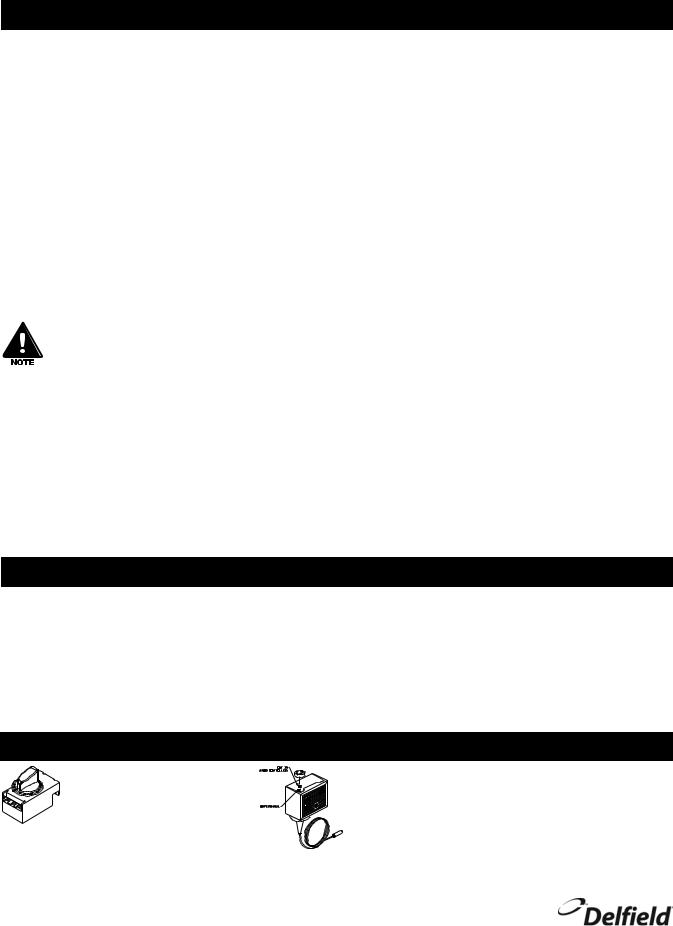
Temperature Control
NLFAC Thermostat Control |
Low Pressure Control, Remaining Self Contained Models |
Set the thermostat toward 1 for |
If it is necessary to adjust the temperature, turn the knob |
higher temperatures and toward |
clockwise as indicated on the control. Make adjustments |
7 for lower temperatures. The |
gradually. It may take an hour to realize the temperature |
refrigerator factory setting is 4 |
change. Milk or beverage dispenser factory settings are 17ºF |
and maintains 38ºF (3ºC) in the |
differential, 34ºF cut in, and 17ºF cut out. Milk and ice cream |
box. |
dispenser factory settings are 25ºF differential, 30ºF cut in, and |
|
5ºF cut out. |
For customer service, call (800) 733-8829, (800) 773-8821, Fax (989) 773-3210, www.delfield.com
 Loading...