


F18 SERIES
Service and Installation Manual
Please read this manual completely before attempting to install or operate this equipment! Notify carrier of damage! Inspect all components immediately. See page 2.
Refrigerated Work Tables, Salad Tables & Freezer Bases
|
|
|
IMPORTANT |
INFORMATION |
|||||
|
|
|
|
|
USE |
||||
|
|
|
|
READ |
BEFORE |
|
|||
|
|
|
|
|
|
INSTRUCTIONS! |
|||
|
|
N |
|
|
THESE |
||||
|
IO |
|
|
|
|
||||
UT |
|
|
|
|
|
|
|
|
|
CA |
|
|
|
SAVE |
|
|
|
|
|
|
PLEASE |
|
|
|
|
Effective Date October 2002 |
|||
|
|
|
|
|
|
||||
|
|
|
|
|
|
|
|
|
|

F18 Series Service and Installation Manual
Contents Serial Number Location
SERIAL NUMBER LOCATION................................................ |
2 |
RECEIVING & INSPECTING .................................................. |
2 |
SPECIFICATIONS .............................................................. |
3-5 |
INSTALLATION...................................................................... |
6 |
OPERATION .......................................................................... |
6 |
CARE AND CLEANING .......................................................... |
7 |
PRESSURE CONTROL SETTINGS......................................... |
7 |
CONDENSING UNIT ASSEMBLY ....................................... |
8-9 |
MULLION COIL ASSEMBLY (REFRIGERATED) ................... |
10 |
MULLION COIL ASSEMBLY (FREEZER).............................. |
11 |
DRAWER ASSEMBLY: LOW PROFILE REFR, 2 & 3 HIGH...12 |
|
CARTRIDGE STYLE DRAWER SYSTEMS............................ |
13 |
DOOR ASSEMBLY: LOW PROFILE...................................... |
14 |
DOOR ASSEMBLY: MARK 7................................................ |
15 |
LOUVERED DOOR ASSEMBLY............................................ |
15 |
REPLACEMENT PARTS LISTS ...................................... |
16-19 |
WIRING DIAGRAMS ........................................................... |
20 |
TROUBLESHOOTING REFERENCE CHART.......................... |
21 |
WARRANTIES............................................................... |
22-23 |
AUTHORIZED PARTS DEPOTS............................ |
(back cover) |
The serial number on all self-contained F18 Series refrigerated work tables and freezer bases is located on the electrical specifications tag affixed inside the compressor section next to the pressure control.
On remote refrigerated bases with doors, the tag is inside the unit on the coil side. On remote refrigerated bases with drawers, the tag is affixed to the drawer divider. On remote freezer bases, the tag is located on the inside back of the unit.
Always have the serial number of your unit available when calling for parts or service. A complete list of authorized Delfield parts depots is shown on the back cover of this manual.
©2002 The Delfield Company. All rights reserved. Reproduction without written permission is prohibited. “Delfield” is a registered trademark of The Delfield Company.
Receiving and Inspecting the Equipment
Even though most equipment is shipped crated, care should be taken during unloading so the equipment is not damaged while being moved into the building.
1.Visually inspect the exterior of the package an skid or container. Any damage should be noted and reported to the delivering carrier immediately.
2.If damaged, open and inspect the contents with the carrier.
3.In the event that the exterior is not damaged, yet upon opening, there is concealed damage to the equipment notify the carrier. Notification should be made verbally as well as in written form.
4.Request an inspection of the concealed equipment. This should be done within 10 days from receipt of the equipment.
5.Check the lower portion of the unit to be sure legs or casters are not bent.
6.Also open the compressor compartment housing and visually inspect the refrigeration package. Be sure lines are secure and base is still intact.
7.Freight carriers can supply the necessary forms upon request.
8.Retain all crating material until an inspection has been made or waived.
Uncrating the Equipment
First cut and remove the banding from around the crate. Remove the front of the crate material, use of some tools will be required. If the unit is on legs remove the top of the crate as well and lift the unit off the skid. If the unit is on casters it can be "rolled" off the skid.
2For customer service, call (800) 733-8829, (800) 773-8821, Fax (989) 773-3210, www.delfield.com
F18 Series Service and Installation Manual
Specifications
|
MODEL |
# OF |
STORAGE |
SHELF AREA |
RECOMMENDED |
VOLTS/HERTZ/ |
|
BTU |
EVAP. CAP. |
|
|
NUMBER |
DOORS |
CU. FT. |
SQ. FT. |
HORSE POWER |
PHASE |
AMPS |
LOAD |
BTU/°TD |
|
|
Remote Refrigerated Work Tables |
|
|
|
|
|
|
|
|
|
|
F18WR31 |
(1) 19” |
6.99 |
2.56 |
1/5 |
115/60/1 |
3.0 |
383 |
120 |
|
|
F18WR39 |
(1) 27” |
9.77 |
3.95 |
1/5 |
115/60/1 |
3.0 |
465 |
120 |
|
|
F18WR44 |
(2) 19” |
11.52 |
5.12 |
1/5 |
115/60/1 |
3.0 |
605 |
120 |
|
|
F18WR52 |
(1) 19” & (1) 27” |
14.31 |
6.51 |
1/5 |
115/60/1 |
3.0 |
686 |
120 |
|
|
F18WR60 |
(2) 27” |
18.85 |
7.90 |
1/4 |
115/60/1 |
3.0 |
768 |
120 |
|
|
F18WR70 |
(2) 32” |
20.59 |
9.64 |
1/4 |
115/60/1 |
3.0 |
869 |
120 |
|
|
F18WR79 |
(2) 27” & (1) 19” |
23.05 |
10.29 |
1/4 |
115/60/1 |
6.0 |
1050 |
240 |
|
|
F18WR87 |
(3) 27” |
25.83 |
11.85 |
1/4 |
115/60/1 |
6.0 |
1131 |
240 |
|
|
MODEL |
# OF |
STORAGE |
SHELF AREA |
|
VOLTS/HERTZ/ |
|
BTU |
BTU |
|
|
NUMBER |
DOORS |
CU. FT. |
SQ. FT. |
HORSE POWER |
PHASE |
AMPS |
LOAD |
SYSTEM |
|
|
|
|
|
|
|
|
|
|
||
|
Self-Contained Refrigerated Work Tables |
|
|
|
|
|
|
|
||
|
F18WC39 |
(1) 19” |
6.99 |
2.56 |
1/5 |
115/60/1 |
8.0 |
383 |
1462 |
|
|
F18WC47 |
(1) 27” |
9.77 |
3.95 |
1/5 |
115/60/1 |
8.0 |
465 |
1462 |
|
|
F18WC52 |
(2) 19” |
11.52 |
5.12 |
1/5 |
115/60/1 |
8.0 |
605 |
1462 |
|
|
F18WC60 |
(1) 19” & (1) 27” |
14.31 |
6.51 |
1/5 |
115/60/1 |
8.0 |
686 |
1462 |
|
|
F18WC68 |
(2) 27” |
18.85 |
7.90 |
1/4 |
115/60/1 |
10.0 |
768 |
1462 |
|
|
F18WC78 |
(2) 32” |
20.59 |
9.64 |
1/4 |
115/60/1 |
10.0 |
869 |
1994 |
|
|
F18WC87 |
(2) 27” & (1) 19” |
23.05 |
10.29 |
1/4 |
115/60/1 |
10.0 |
1050 |
2261 |
|
|
F18WC95 |
(3) 27” |
25.83 |
11.85 |
1/4 |
115/60/1 |
10.0 |
1131 |
2261 |
|
|
A 5-15P NEMA plug is used on self-contained units |
|
|
|
|
|
|
|
||
|
MODEL |
# OF |
STORAGE |
# OF |
RECOMMENDED |
VOLTS/HERTZ/ |
|
BTU DESIGN |
EVAP. CAP. BTU/°TD |
|
|
NUMBER |
DOORS |
CU. FT. |
PANS |
HORSE POWER |
PHASE |
AMPS |
BASE/RAIL |
BASE/RAIL |
|
|
|
|
|
|
|
|
|
|
||
|
Remote Refrigerated Mega Top Salad Tables |
|
|
|
|
|
|
|
||
|
F18MR31A |
(1) 19” |
4.11 |
6 |
1/4 |
115/60/1 |
3.0 |
280/265 |
120/12 |
|
|
F18MR44A |
(2) 19” |
6.94 |
6 |
1/4 |
115/60/1 |
3.0 |
444/265 |
120/12 |
|
|
F18MR44D |
(2) 19” |
6.94 |
12 |
1/4 |
115/60/1 |
3.0 |
444/529 |
120/22 |
|
|
F18MR52A |
(1) 19” & (1) 27” |
8.69 |
6 |
1/3 |
115/60/1 |
3.0 |
515/265 |
120/12 |
|
|
F18MR52D |
(1) 19” & (1) 27” |
8.69 |
12 |
1/3 |
115/60/1 |
3.0 |
515/529 |
120/22 |
|
|
F18MR52E |
(1) 19” & (1) 27” |
8.69 |
18 |
1/3 |
115/60/1 |
3.0 |
515/794 |
120/31 |
|
|
|
|
|
|
|
|
|
|
|
|
|
MODEL |
# OF |
STORAGE |
# OF |
|
VOLTS/HERTZ/ |
|
BTU DESIGN |
BTU SYSTEM CAP. |
|
|
NUMBER |
DOORS |
CU. FT. |
PANS |
HORSE POWER |
PHASE |
AMPS |
BASE/RAIL |
BASE/RAIL |
|
|
|
|
|
|
|
|
|
|||
|
Self-Contained Refrigerated Mega Top Salad Tables |
|
|
|
|
|
|
|||
|
F18MC39A |
(1) 19” |
4.11 |
6 |
1/4 |
115/60/1 |
10.0 |
280/265 |
1903/925 |
|
|
F18MC39D |
(1) 19” |
4.11 |
12 |
1/4 |
115/60/1 |
10.0 |
280/529 |
1903/1156 |
|
|
F18MC52A |
(2) 19” |
6.94 |
6 |
1/4 |
115/60/1 |
10.0 |
444/265 |
1903/925 |
|
|
F18MC52D |
(2) 19” |
6.94 |
12 |
1/4 |
115/60/1 |
10.0 |
444/529 |
1903/1156 |
|
|
F18MC52E |
(2) 19” |
6.94 |
18 |
1/4 |
115/60/1 |
10.0 |
444/794 |
1903/1321 |
|
|
F18MC60A |
(1) 19” & (1) 27” |
8.69 |
6 |
1/4 |
115/60/1 |
10.0 |
515/265 |
2314/864 |
|
|
F18MC60D |
(1) 19” & (1) 27” |
8.69 |
12 |
1/4 |
115/60/1 |
10.0 |
515/529 |
2314/1141 |
|
|
F18MC60E |
(1) 19” & (1) 27” |
8.69 |
18 |
1/4 |
115/60/1 |
10.0 |
515/794 |
2314/1361 |
|
|
F18MC60F |
(1) 19” & (1) 27” |
8.69 |
24 |
1/4 |
115/60/1 |
10.0 |
515/1058 |
2314/1540 |
|
A 5-15P NEMA plug is used on self-contained units
3 |
3 |
For customer service, call (800) 733-8829, (800) 773-8821, Fax (989) 773-3210, www.delfield.com |
F18 Series Service and Installation Manual
Specifications
|
MODEL |
# OF |
|
SHELF AREA |
# OF |
RECOMMENDED |
VOLTS/HERTZ/ |
|
BTU DESIGN |
EVAP. CAP. |
|
|
NUMBER |
DOORS |
|
SQ. FT. |
PANS |
HORSE POWER |
PHASE |
AMPS |
BASE/RAIL |
BTU/°TD |
|
|
Remote Refrigerated Salad Top Tables |
|
|
|
|
|
|
|
|
||
|
F18SR31A |
(1) 19” |
|
2.56 |
6 |
1/4 |
115/60/1 |
3.0 |
280/265 |
120 |
|
|
F18SR44A |
(2) 19” |
|
5.12 |
6 |
1/4 |
115/60/1 |
3.0 |
491/441 |
120 |
|
|
F18SR44B |
(2) 19” |
|
5.12 |
8 |
1/4 |
115/60/1 |
3.0 |
491/441 |
120 |
|
|
F18SR44C |
(2) 19” |
|
5.12 |
10 |
1/4 |
115/60/1 |
3.0 |
491/441 |
120 |
|
|
F18SR52A |
(1) 19” & (1) 27” |
|
6.51 |
6 |
1/4 |
115/60/1 |
3.0 |
532/529 |
120 |
|
|
F18SR52B |
(1) 19” & (1) 27” |
|
6.51 |
8 |
1/4 |
115/60/1 |
3.0 |
532/529 |
120 |
|
|
F18SR52C |
(1) 19” & (1) 27” |
|
6.51 |
10 |
1/4 |
115/60/1 |
3.0 |
532/529 |
120 |
|
|
F18SR52D |
(1) 19” & (1) 27” |
|
6.51 |
12 |
1/4 |
115/60/1 |
3.0 |
532/529 |
120 |
|
|
MODEL |
# OF |
|
SHELF AREA |
# OF |
|
VOLTS/HERTZ/ |
|
BTU DESIGN |
BTU SYSTEM CAP. |
|
|
NUMBER |
DOORS |
|
SQ. FT. |
PANS |
HORSE POWER |
PHASE |
AMPS |
BASE/RAIL |
BASE/RAIL |
|
|
Self-Contained Refrigerated Salad Top Tables |
|
|
|
|
|
|
|
|||
|
F18SC39A |
(1) 19” |
|
2.56 |
6 |
1/4 |
115/60/1 |
10.0 |
280/265 |
1903/745 |
|
|
F18SC39B |
(1) 19” |
|
2.56 |
8 |
1/4 |
115/60/1 |
10.0 |
280/353 |
1903/867 |
|
|
F18SC52A |
(2) 19” |
|
5.12 |
6 |
1/4 |
115/60/1 |
10.0 |
444/265 |
1903/745 |
|
|
F18SC52B |
(2) 19” |
|
5.12 |
8 |
1/4 |
115/60/1 |
10.0 |
444/353 |
1903/867 |
|
|
F18SC52C |
(2) 19” |
|
5.12 |
10 |
1/4 |
115/60/1 |
10.0 |
444/441 |
1903/971 |
|
|
F18SC52D |
(2) 19” |
|
5.12 |
12 |
1/4 |
115/60/1 |
10.0 |
444/529 |
1903/1061 |
|
|
F18SC60A |
(2) 19” & (1) 27” |
|
6.51 |
6 |
1/4 |
115/60/1 |
10.0 |
515/265 |
2314/667 |
|
|
F18SC60B |
(2) 19” & (1) 27” |
|
6.51 |
8 |
1/4 |
115/60/1 |
10.0 |
515/353 |
2314/798 |
|
|
F18SC60C |
(2) 19” & (1) 27” |
|
6.51 |
10 |
1/4 |
115/60/1 |
10.0 |
515/441 |
2314/916 |
|
|
F18SC60D |
(2) 19” & (1) 27” |
|
6.51 |
12 |
1/4 |
115/60/1 |
10.0 |
515/529 |
2314/1023 |
|
|
A 5-15P NEMA plug is used on self-contained units |
|
|
|
|
|
|
|
|||
|
|
|
|
|
|
|
|
|
|
|
|
|
MODEL |
# OF |
STORAGE |
SHELF AREA |
# OF |
RECOMMENDED |
VOLTS/HERTZ/ |
|
BTU DESIGN LOAD |
EVAP. CAP. |
|
|
NUMBER |
DOORS |
CU. FT. |
SQ. FT. |
PANS |
HORSE POWER |
PHASE |
AMPS |
BASE/RAIL |
BTU/°TD |
|
|
Remote Refrigerated Reduced Height Rail |
|
|
|
|
|
|
|
|
||
|
F18DR44 |
(2) 19” |
9.49 |
5.12 |
10 |
1/4 |
115/60/1 |
3.0 |
547/441 |
120/19 |
|
|
F18DR52 |
(1) 19” & (1) 27” |
11.81 |
6.51 |
12 |
1/3 |
115/60/1 |
3.0 |
625/529 |
120/23 |
|
|
F18DR60 |
(2) 27” |
14.14 |
7.9 |
16 |
1/3 |
115/60/1 |
5.0 |
703/617 |
120/26 |
|
|
F18DR70 |
(2) 32” |
17.05 |
9.64 |
18 |
1/2 |
115/60/1 |
5.0 |
800/794 |
120/32 |
|
|
F18DR79 |
(1) 19” & (2) 27” |
18.68 |
10.29 |
18 |
1/2 |
115/60/1 |
5.0 |
962/882 |
240/36 |
|
|
F18DR87 |
(3) 27” |
21.30 |
11.85 |
22 |
3/4 |
115/60/1 |
5.0 |
1032/970 |
240/39 |
|
|
MODEL |
# OF |
STORAGE |
SHELF AREA |
# OF |
|
VOLTS/HERTZ/ |
|
BTU LOAD |
BTU SYSTEM CAP. |
|
|
NUMBER |
DOORS |
CU. FT. |
SQ. FT. |
PANS |
HORSE POWER |
PHASE |
AMPS |
BASE/RAIL |
BASE/RAIL |
|
|
|
|
|
|
|
|
|
|
|||
|
Self-Contained Refrigerated Reduced Height Rail |
|
|
|
|
|
|
|
|||
|
F18DC52 |
(2) 19” |
9.49 |
5.12 |
12 |
1/4 |
115/60/1 |
10.0 |
547/529 |
1903/1061 |
|
|
F18DC60 |
(1) 19” & (1) 27” |
11.81 |
6.51 |
14 |
1/3 |
115/60/1 |
12.0 |
625/617 |
2314/1121 |
|
|
F18DC68 |
(2) 27” |
14.14 |
7.9 |
18 |
1/3 |
115/60/1 |
12.0 |
703/794 |
2314/1544 |
|
|
F18DC82 |
(2) 32” |
17.05 |
9.64 |
20 |
1/2 |
115/60/1 |
14.0 |
800/882 |
3097/1648 |
|
|
F18DC91 |
(1) 19” & (2) 27” |
18.68 |
10.29 |
22 |
1/2 |
115/60/1 |
14.0 |
962/1058 |
3807/1839 |
|
|
F18DC99 |
(3) 27” |
21.30 |
11.85 |
24 |
3/4 |
115/60/1 |
16.0 |
1032/1147 |
5286/2191 |
|
A 5-15P NEMA plug is used on F18RC52, F18RC60 & F18RC68 . A 5-20P NEMA plug is used on , F18RC82, F18RC91, & F18RC99.
4 |
For customer service, call (800) 733-8829, (800) 773-8821, Fax (989) 773-3210, www.delfield.com |
F18 Series Service and Installation Manual
Specifications
MODEL |
# OF |
STORAGE |
SHELF AREA |
# OF |
RECOMMENDED |
VOLTS/HERTZ/ |
|
BTU DESIGN LOAD |
EVAP. CAP. |
NUMBER |
DOORS |
CU. FT. |
SQ. FT. |
PANS |
HORSE POWER |
PHASE |
AMPS |
BASE/RAIL |
BTU/°TD |
Remote Refrigerated Reduced Height Rail |
|
|
|
|
|
|
|
||
F18RR44 |
(2) 19” |
9.49 |
5.12 |
10 |
1/4 |
115/60/1 |
3.0 |
547/441 |
120/19 |
F18RR52 |
(1) 19” & (1) 27” |
11.81 |
6.51 |
12 |
1/3 |
115/60/1 |
3.0 |
625/529 |
120/23 |
F18RR60 |
(2) 27” |
14.14 |
7.9 |
16 |
1/3 |
115/60/1 |
5.0 |
703/617 |
120/26 |
F18RR70 |
(2) 32” |
17.05 |
9.64 |
18 |
1/2 |
115/60/1 |
5.0 |
800/794 |
120/32 |
F18RR79 |
(1) 19” & (2) 27” |
18.68 |
10.29 |
18 |
1/2 |
115/60/1 |
5.0 |
962/882 |
240/36 |
F18RR87 |
(3) 27” |
21.30 |
11.85 |
22 |
3/4 |
115/60/1 |
5.0 |
1032/970 |
240/39 |
MODEL |
# OF |
STORAGE |
SHELF AREA |
# OF |
|
VOLTS/HERTZ/ |
|
BTU LOAD |
BTU SYSTEM CAP. |
NUMBER |
DOORS |
CU. FT. |
SQ. FT. |
PANS |
HORSE POWER |
PHASE |
AMPS |
BASE/RAIL |
BASE/RAIL |
|
|
|
|
|
|
|
|||
Self-Contained Refrigerated Reduced Height Rail |
|
|
|
|
|
|
|||
F18RC52 |
(2) 19” |
9.49 |
5.12 |
12 |
1/4 |
115/60/1 |
10.0 |
547/529 |
1903/1061 |
F18RC60 |
(1) 19” & (1) 27” |
11.81 |
6.51 |
14 |
1/3 |
115/60/1 |
12.0 |
625/617 |
2314/1121 |
F18RC68 |
(2) 27” |
14.14 |
7.9 |
18 |
1/3 |
115/60/1 |
12.0 |
703/794 |
2314/1544 |
F18RC82 |
(2) 32” |
17.05 |
9.64 |
20 |
1/2 |
115/60/1 |
14.0 |
800/882 |
3097/1648 |
F18RC91 |
(1) 19” & (2) 27” |
18.68 |
10.29 |
22 |
1/2 |
115/60/1 |
14.0 |
962/1058 |
3807/1839 |
F18RC99 |
(3) 27” |
21.30 |
11.85 |
24 |
3/4 |
115/60/1 |
16.0 |
1032/1147 |
5286/2191 |
A 5-15P NEMA plug is used on F18RC52, F18RC60 & F18RC68 . A 5-20P NEMA plug is used on , F18RC82, F18RC91, & F18RC99.
|
MODEL |
# OF |
STORAGE |
SHELF AREA |
RECOMMENDED |
VOLTS/HERTZ/ |
|
BTU |
EVAP. CAP. |
|
|
NUMBER |
DOORS |
CU. FT. |
SQ. FT. |
HORSE POWER |
PHASE |
AMPS |
LOAD |
BTU/°TD |
|
|
|
|
|
|
|
|
|
|
|
|
|
Remote Freezer Base |
|
|
|
|
|
|
|
|
|
|
F18FR35 |
(1) 19” |
5.58 |
2.56 |
1/3 |
115/60/1 |
10.0 |
943 |
160 |
|
|
F18FR50 |
(2) 19” |
12.21 |
5.12 |
1/2 |
115/60/1 |
10.0 |
1471 |
160 |
|
|
F18FR58 |
(1) 19” & (1) 27” |
15 |
6.51 |
3/4 |
115/60/1 |
10.0 |
1844 |
160 |
|
|
F18FR66 |
(2) 27” |
17.79 |
7.9 |
3/4 |
115/60/1 |
10.0 |
2020 |
160 |
|
|
F18FR76 |
(2) 32” |
21.28 |
9.64 |
3/4 |
115/60/1 |
10.0 |
2437 |
160 |
|
|
|
|
|
|
|
|
|
|
|
|
|
MODEL |
# OF |
STORAGE |
SHELF AREA |
|
VOLTS/HERTZ/ |
|
BTU |
EVAP. CAP. |
|
|
NUMBER |
DOORS |
CU. FT. |
SQ. FT. |
HORSE POWER |
PHASE |
AMPS |
LOAD |
BTU/°TD |
|
|
|
|
|
|
|
|
|
|
|
|
|
Self-Contained Freezer Base |
|
|
|
|
|
|
|
|
|
|
F18FC43 |
(1) 19” |
5.58 |
2.56 |
1/3 |
115/60/1 |
10.0 |
943 |
1558 |
|
|
F18FC62 |
(2) 19” |
12.21 |
5.12 |
1/2 |
115/60/1 |
12.0 |
1471 |
1776 |
|
|
F18FC70 |
(1) 19” & (1) 27” |
15 |
6.51 |
3/4 |
115/60/1 |
16.0 |
1647 |
2713 |
|
|
F18FC78 |
(2) 27” |
17.79 |
7.9 |
3/4 |
115/60/1 |
16.0 |
1824 |
2713 |
|
|
F18FC88 |
(2) 32” |
21.28 |
9.64 |
3/4 |
115/60/1 |
16.0 |
2045 |
2713 |
|
A 5-15P NEMA plug is used on F18FC43 & F18FC62. A 5-20P NEMA plug is used on F18FC70, F18FC78 & F18FC88.
5 |
5 |
For customer service, call (800) 733-8829, (800) 773-8821, Fax (989) 773-3210, www.delfield.com |

F18 Series Service and Installation Manual
Installation
Location
Be sure the location chosen has a floor strong enough to support the total weight of the cabinet and contents. A fully loaded 72” long model may weigh as much as 1500 pounds! Reinforce the floor as necessary to provide for maximum loading.
It is very important to allow for proper air flow, both inside and outside.
Avoid hot corners and locations near stoves, ovens and other pieces of cooking equipment.
It is recommended that the unit be installed no closer than 1” from any wall. Do not install the unit near any combustible material or
object affected by heat or moisture.
Leveling
A level cabinet looks better and will perform better because the drain pan will drain properly, the doors will line up with the frames properly, and the cabinet will not be subject to undue strain.
A unit on legs will have an adjustable bullet foot on each leg, adjust each for a level unit. A unit on casters will not be adjustable. Be sure the unit is on a level floor, make necessary changes to the floor for proper level.
Lock all front casters to ensure the stability of the unit.
Plumbing
Self-contained models are standard with a condensate evaporator. If, for some reason a unit does not have a condensate evaporator, or if the evaporator fails, the unit’s drain must have an outlet to an appropriate drainage area or
Operation
container. A refrigerated rail will have a 1" drain which will need to be run to an appropriate floor drain or container. The drain will be stubbed to the bottom of the machine compartment. Either run drain to a floor drain or add a valve
to the base of the machine compartment and drain the rail to a container when convenient. The LiquiTec option will NOT have a drain available.
Moisture collecting from improper drainage can create a slippery surface on the floor and a hazard
to employees. It is the owner’s and operator’s
 responsibility to provide a container or outlet for CAUTION drainage.
Electrical connection
Refer to the amperage data on pages 3-5, the serial tag, your local code or the National Electrical Code to be sure the unit is connected to the proper power source. A protected circuit of the correct voltage and amperage must be run for connection of the line cord, or permanent connection of the unit.
Self-contained units with a cord and plug have an ON/OFF switch located directly behind the louvered panel covering the compressor section. Simply turn the switch to ON to begin operation.
The power switch must be turned to OFF and the unit disconnected from the power source whenever performing service or maintenance functions.
Never operate the unit without the louvered panel in place!
If electrical receptacles are to be mounted in the unit’s backsplash, they must be wired independently from the existing unit wiring.
After turning the ON/OFF switch to ON the unit’s compressor will begin operating. Delfield refrigerated bases are designed to maintain an operational temperature of 36°F to 40°F.
Temperature in the salad top and refrigerated rail opening is 33°F to 41°F with pans recessed 3” on a standard wrapped refrigerated rail or flush with the LiquiTec option at 86°F ambient room temperature. Freezer bases are designed to maintain an operational temperature of 0°F.
Do not place hot pans on/against the blue ABS liner. Do not throw items into the storage area. Failure to heed these recommendations could result in damage to the interior of the cabinet or
to the blower coil.
Overloading the storage area, restricting the air flow, and continuous opening and closing of the doors and drawers will hamper the units ability to maintain operational temperature.
Refrigerated rail units
Product in the rail should be removed to the refrigerated base at the end of the day. This allows you to turn the rail off at night to save energy and the rail will have time to defrost as needed. It also helps maintain product quality. The standard wrapped refrigerated


 units are controlled by the pressure control which is set to maintain the proper rail temperature an on/off switch is also provided for the rail and is required to be shut off at night. The rail switch shuts off the rail only. With a LiquiTec rail a thermostat is provided to maintain rail temperature as well as the rail on/off switch. The LiquiTec rail is required to be shut off at night as well to allow for defrosting. To ensure product quality in the rail it is recommended that product be rotated every four hours.
If adding any item to the unit, be sure to keep in mind the location of the refrigeration lines on wrapped rail units. A refrigeration leak in a rail


 is extremely difficult and costly to repair. In some cases it cannot be repaired at all.
6For customer service, call (800) 733-8829, (800) 773-8821, Fax (989) 773-3210, www.delfield.com
F18 Series Service and Installation Manual
Care and Cleaning
Cleaning the cabinet
The interior and exterior can be cleaned using soap and warm water. If this is not sufficient, try ammonia and water or nonabrasive liquid cleaner. When cleaning the exterior, always rub with the “grain” of the stainless steel to avoid marring the finish. Do not use an abrasive cleaner because it will scratch the stainless steel and plastic.
The interior of the cabinet should be cleaned daily with a nonabrasive cleaner and a nonabrasive pad. If necessary, a mild abrasive may be used on the interior of the pans only. Never use steel wool. No drains are provided with rails, after defrosting water will accumulate in the rail. This will need to be cleaned out thoroughly before restarting the rail as it will freeze and severely reduce the efficiency of the rail.
Cleaning the condenser
In order to maintain proper refrigeration performance, the condenser fins must be cleaned of dust, dirt and grease regularly. It is recommended that this be done at least every three months. If conditions 

 are such that the condenser is totally blocked
in three months, the frequency of cleaning should be increased. Clean the condenser with a vacuum cleaner or stiff brush. If extremely dirty, a commercially available condenser cleaner may be required.
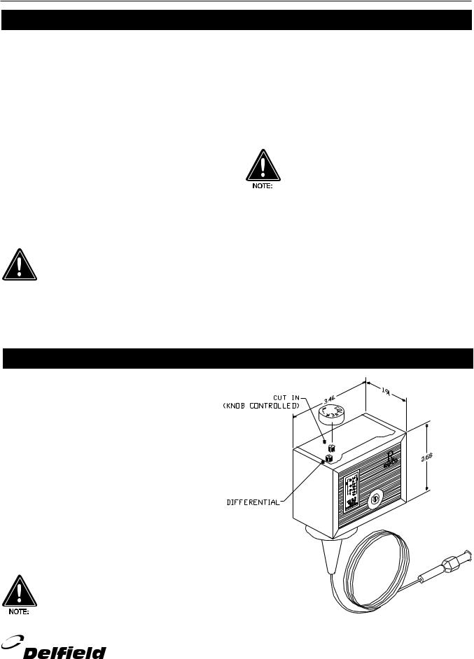
Pressure Control Settings
Factory recommended low-pressure control settings are: HFC-404A refrigerators: 85# cut-in and 65# cut-out to maintain approximate interior
temperature of 38°F. Differential setting of 20#.
HFC-404A freezers: 32# cut-in and 8# cut-out to maintain approximate interior temperature of 0°F to 5°F.
Differential setting of 24#.
HFC-404A refrigerators with LiquiTec Rail:
20# cut-in and 10# cut-out to Differential setting of 10# Temperature control for LiquiTec Rail, 25°F cut in and 18°F cut-out.
Pressure control settings are measured in pounds, not fahrenheit.
Cleaning door gaskets
Door gaskets should be cleaned as required to maintain their ability to seal properly. Do not use sharp tools or knives to scrape the bellows as this may tear the gasket and eliminate its ability to seal. A soft bristle brush and solution of soap and water should be all that is required to keep the gaskets clean. Do not use full strength degreasing agents on the gasket because they could cause the gasket to become brittle and crack.
Consistent cleaning of the coil will enhance the operation of the unit by reducing energy consumption as well as extend the life of the compressor.
Preventing blower coil corrosion
To help prevent corrosion of the blower coil, store all acidic items, such as pickles and tomatoes, in sealable containers. Immediately wipe up all spills of items.
7 |
7 |
For customer service, call (800) 733-8829, (800) 773-8821, Fax (989) 773-3210, www.delfield.com |

F18 Series Service and Installation Manual
Condensing Unit Assembly
5
8See below for receiver tank part #
1
2
4
1/5 HORSE POWER |
|
Used On: F18WC39, 47, 52 & 60 |
|||
|
|
|
|||
|
MEDIUM |
|
|
|
|
|
|
|
|
|
|
|
DELFIELD |
|
TECUMSEH |
|
|
KEY |
PART# |
COND. PART# |
DESCRIPTION |
||
|
3526747 |
AEA9415ZXAEC2A540-2 |
1/5 H.P. med. condensing unit |
||
|
|
|
|
||
1 |
3526762 |
AE570AT-907-J7 |
compressor |
||
2 |
|
|
8200EMBJ30 |
relay, start |
|
3 |
|
|
85PS110C76 |
capacitor |
|
4 |
|
|
8300MRTN96 |
overload protector |
|
|
|
|
|
|
|
5 |
|
|
810M006B45 |
motor, fan, condenser |
|
6 |
|
|
50837 |
|
coil, condenser |
|
|
|
|
|
|
7 |
|
|
51561 |
|
blade, fan |
8 |
|
|
51080 |
|
receiver tank |
Refrigerant charges — gas refrigerant 404A — 16 oz.
7
6
#6 - Condensing coil - requires periodic cleaning.
3
|
|
|
|
Used On: F18SC39, 52 & 60; F18WC68, 78, |
|
1/4 HORSE POWER |
|
||||
|
87 & 95; F18MC39, 52, & 60; F18DC52 and |
||||
|
MEDIUM |
|
|
F18RC52 |
|
|
DELFIELD |
|
TECUMSEH |
|
|
KEY |
PART# |
|
PART# |
DESCRIPTION |
|
|
3526745 |
AEA9422ZXAEC2C462-2 |
1/4 H.P. med. condensing unit |
||
|
|
|
|
|
|
1 |
3526768 |
AE590AT-900-J7 |
compressor |
||
2 |
|
|
820RR12E72 |
relay, start |
|
3 |
|
|
85PS165C27 |
capacitor |
|
4 |
|
|
8300MRTN28 |
overload protector |
|
|
|
|
|
|
|
5 |
|
|
810M006B45 |
motor, fan, condenser |
|
6 |
|
|
50837 |
|
coil, condenser |
|
|
|
|
|
|
7 |
|
|
51561 |
|
blade, fan |
8 |
|
|
51080 |
|
receiver tank |
Refrigerant charges — gas refrigerant 404A — 16 oz.
8For customer service, call (800) 733-8829, (800) 773-8821, Fax (989) 773-3210, www.delfield.com
 Loading...