


 Delfield™ ®
F2000 and F17 Series Equipment Stands
Service, Installation and Care Manual
Please read this manual completely before attempting to install or operate this equipment! Notify carrier of damage! Inspect all components immediately. See page 2.
Warning
To assure proper operation a 2" airspace must be maintained between the lowest part of any cooking equipment and the top of this unit. Cooking equipment must have a barrier (i.e. bottom, drip pan) between its heat source and the top of the equipment stand. Failure to comply with this could severely damage the equipment stand and void all warranties.
Important |
Information |
|||||
|
|
Use |
||||
Read |
Before |
|
||||
These |
Instructions! |
|||||
|
Save |
|||||
Please |
|
|
||||
|
|
|
|
|||
|
|
|
|
|
||
July 2012
F2000/F17 Series Equipment Stand Service and Installation Manual
Important Warning And Safety Information
WARNING |
Read This Manual Thoroughly Before Operating, Installing, Or Performing Maintenance On The Equipment. |
WARNING |
Failure To Follow Instructions In This Manual Can Cause Property Damage, Injury Or Death. |
WARNING |
Do Not Store Or Use Gasoline Or Other Flammable Vapors Or Liquids In The Vicinity Of This Or Any Other |
|
Appliance. |
WARNING |
Unless All Cover And Access Panels Are In Place And Properly Secured, Do Not Operate This Equipment. |
WARNING |
This Appliance Is Not Intended For Use By Persons Who Lack Experience Or Knowledge, Unless They Have |
|
Been Given Supervision Or Instruction Concerning Use Of The Appliance By A Person Responsible For Their |
|
Safety. |
WARNING |
This Appliance Is Not To Be Played With. |
Warning |
Do Not Clean With Water Jet. |
WARNING |
Do Not Use Electrical Appliances Inside The Food Storage Compartment Of This Appliance. |
CAUTION |
Observe the following: |
|
|
• |
Minimum clearances must be maintained from all walls and combustible materials. |
|
• |
Keep the equipment area free and clear of combustible material. |
|
• |
Allow adequate clearance for air openings. |
|
• |
Operate equipment only on the type of electricity indicated on the specification plate. |
|
• |
Unplug the unit before making any repairs. |
|
• |
Retain this manual for future reference. |
2 |
For customer service, call (800) 733-8829, (800) 733-8821, Fax (989) 773-3210, www.delfield.com |
Delfield® |
|
|
™ |
Contents |
|
Receiving And Inspecting...................................................... |
3 |
F2000 Specifications............................................................. |
4 |
F17 Specifications................................................................. |
5 |
Installation......................................................................... |
6-7 |
Operation............................................................................... |
7 |
Temperature Control Settings................................................ |
8 |
Maximum Cooking Equipment Weight Capacity.................... |
8 |
Maintenance.................................................................... |
9-10 |
Refrigerator Wiring Diagrams.............................................. |
11 |
Freezer Wiring Diagrams..................................................... |
12 |
Replacement Parts by Model......................................... |
13-16 |
Condensing Unit Assemblies......................................... |
17-18 |
Evaporator Coil Assemblies................................................. |
19 |
Drawer Assemblies.............................................................. |
20 |
Replacement Part Prints...................................................... |
21 |
Standard Labor Guidelines.................................................. |
22 |
Warranties..................................................................... |
23-25 |
Notes............................................................................. |
26-27 |
F2000/F17 Series Equipment Stand Service and Installation Manual
Serial Number Location
The serial number on remote models is located behind the 6" (15cm) stainless steel panel.
The serial number on self-contained models is located in the compressor housing.
The serial number tag shows the refrigerant used and the amount of charge and amperage.
Always have the serial number of your unit available when calling for parts and service.
©2012 The Delfield Company. All rights reserved. Reproduction without written permission is prohibited. “Delfield” is a registered trademark of The Delfield Company.
Regulatory Certifications
All models are certified by:
National Sanitation Foundation (NSF)
Refrigerated models are certified by:
Underwriters Laboratories (UL)
Receiving and Inspecting the Equipment
Even though most equipment is shipped crated, care should be taken during unloading so the equipment is not damaged while being moved into the building.
1.Visually inspect the exterior of the package and skid or container. Any damage should be noted and reported to the delivering carrier immediately.
2.If damaged, open and inspect the contents with the carrier.
3.In the event that the exterior is not damaged, yet upon opening, there is concealed damage to the equipment notify the carrier. Notification should be made verbally as well as in written form.
4.Request an inspection by the shipping company of the damaged equipment. This should be done within 10 days from receipt of the equipment.
5.Check the lower portion of the unit to be sure legs or casters are not bent.
6.Also open the compressor compartment housing and visually inspect the refrigeration package. Be sure lines are secure and base is still intact.
7.Freight carriers can supply the necessary damage forms upon request.
8.Retain all crating material until an inspection has been made or waived.
Uncrating the Equipment
First cut and remove the banding from around the crate. Remove the front of the crate material, use of some tools will be required. If the unit is on legs remove the top of the crate as well and lift the unit off the skid. If the unit is on casters it can be "rolled" off the skid.
Delfield® |
For customer service, call (800) 733-8829, (800) 733-8821, Fax (989) 773-3210, www.delfield.com |
3 |
™ |
|
|

F2000/F17 Series Equipment Stand Service and Installation Manual
F2000 Specifications
Self Contained Low-Profile Freezer Base Equipment Stands
Model |
12x20 Pan |
# Of Drawers |
Voltage/Hertz/ |
Amps |
H.P. |
Nema |
Shipping Weight |
BTU |
BTU |
Evap BTU/ |
|
|
Capacity |
|
|
Phase |
|
|
Plug |
|
Load |
System |
TD/Temp |
|
|
|
|
|
|
|
|
|
|
|
|
F2660 |
4 |
(2) 32" |
115/60/1 |
11.0 |
1/2 |
5-15P |
418lbs/190kg |
925 |
1776 |
160/11º/-14º |
|
|
|
|
|
|
|
|
|
|
|
|
|
F2694 |
8 |
(4) 32" |
115/60/1 |
16.0 |
3/4 |
5-20P |
500lbs/227kg |
1558 |
2713 |
160/17º/-20º |
|
|
|
|
|
|
|
|
|
|
|
|
|
Remote Low-Profile Freezer Base Equipment Stands |
|
|
|
|
|
|
|||||
|
|
|
|
|
|
|
|
|
|
|
|
Model |
12x20 Pan |
# Of Drawers |
Voltage/Hertz/ |
Amps |
H.P. |
Nema |
Shipping Weight |
BTU |
BTU |
Evap BTU/ |
|
|
Capacity |
|
|
Phase |
|
|
Plug |
|
Load |
System |
TD/Temp |
|
|
|
|
|
|
|
|
|
|
|
|
F2748 |
4 |
(2) 32" |
115/60/1 |
10.0 |
N/A |
N/A |
295lbs/134kg |
1032 |
N/A |
160/8º/-11º |
|
|
|
|
|
|
|
|
|
|
|
|
|
F2776 |
8 |
(4) 32" |
115/60/1 |
10.0 |
N/A |
N/A |
375lbs/170kg |
1770 |
N/A |
160/12º/-15º |
|
|
|
|
|
|
|
|
|
|
|
|
|
Remote Low-Profile Refrigerator Base Equipment Stands |
|
|
|
|
|
|
|||||
|
|
|
|
|
|
|
|
|
|
|
|
Model |
12x20 Pan |
# Of Drawers |
Voltage/Hertz/ |
Amps |
H.P. |
Nema |
Shipping Weight |
BTU |
BTU |
Evap BTU/ |
|
|
Capacity |
|
|
Phase |
|
|
Plug |
|
Load |
System |
TD/Temp |
|
|
|
|
|
|
|
|
|
|
|
|
F2852 |
4 |
(2) |
19" (2) 27" |
115/60/1 |
3.0 |
N/A |
N/A |
278lbs/126kg |
452 |
N/A |
120/5º/32º |
|
|
|
|
|
|
|
|
|
|
|
|
F2856 |
4 |
(2) |
32" |
115/60/1 |
3.0 |
N/A |
N/A |
299lbs/136kg |
461 |
N/A |
120/5º/32º |
|
|
|
|
|
|
|
|
|
|
|
|
F2862 |
6 |
(2) |
19" (2) 27" |
115/60/1 |
3.0 |
N/A |
N/A |
331lbs/150kg |
575 |
N/A |
120/6º/31º |
|
|
|
|
|
|
|
|
|
|
|
|
F2875 |
8 |
(2) |
27" (2) 32" |
115/60/1 |
3.0 |
N/A |
N/A |
401lbs/182kg |
717 |
N/A |
240/4º/33º |
|
|
|
|
|
|
|
|
|
|
|
|
F2880 |
8 |
(4) |
32" |
115/60/1 |
3.0 |
N/A |
N/A |
428lbs/194kg |
726 |
N/A |
240/4º/33º |
|
|
|
|
|
|
|
|
|
|
|
|
F2887 |
10 |
(2) |
19" (4) 27" |
115/60/1 |
6.0 |
N/A |
N/A |
466lbs/211kg |
868 |
N/A |
240/4º/33º |
|
|
|
|
|
|
|
|
|
|
|
|
F2899 |
12 |
(6) |
27" |
115/60/1 |
6.0 |
N/A |
N/A |
530lbs/240kg |
1029 |
N/A |
240/5º/32º |
|
|
|
|
|
|
|
|
|
|
|
|
F28110 |
12 |
(6) |
32" |
115/60/1 |
6.0 |
N/A |
N/A |
588lbs/267kg |
1143 |
N/A |
240/5º/32º |
|
|
|
|
|
|
|
|
|
|
|
|
Self Contained Low-Profile Refrigerator Base Equipment Stands |
|
|
|
|
|
||||||
|
|
|
|
|
|
|
|
|
|
|
|
Model |
12x20 Pan |
# Of Drawers |
Voltage/Hertz/ |
Amps |
H.P. |
Nema |
Shipping Weight |
BTU |
BTU |
Evap BTU/ |
|
|
Capacity |
|
|
Phase |
|
|
Plug |
|
Load |
System |
TD/Temp |
|
|
|
|
|
|
|
|
|
|
|
|
F2952C |
4 |
(2) |
32" |
115/60/1 |
8.0 |
1/5 |
5-15P |
398lbs/181kg |
452 |
1727 |
120/14º/23º |
|
|
|
|
|
|
|
|
|
|
|
|
F2956C |
4 |
(2) |
32" |
115/60/1 |
8.0 |
1/5 |
5-15P |
405lbs/184kg |
461 |
1727 |
120/14º/23º |
|
|
|
|
|
|
|
|
|
|
|
|
F2962C |
6 |
(2) |
19" (2) 27" |
115/60/1 |
8.0 |
1/5 |
5-15P |
479lbs/217kg |
575 |
1727 |
120/14º/23º |
|
|
|
|
|
|
|
|
|
|
|
|
F2975C |
8 |
(2) |
27" (2) 32" |
115/60/1 |
10.0 |
1/4 |
5-15P |
540lbs/245kg |
717 |
2341 |
144/16º/21º |
|
|
|
|
|
|
|
|
|
|
|
|
F2980C |
8 |
(4) |
32" |
115/60/1 |
10.0 |
1/4 |
5-15P |
578lbs/262kg |
726 |
2341 |
144/16º/21º |
|
|
|
|
|
|
|
|
|
|
|
|
F2987C |
10 |
(2) |
19" (4) 27" |
115/60/1 |
10.0 |
1/4 |
5-15P |
672lbs/305kg |
868 |
2341 |
144/16º/21º |
|
|
|
|
|
|
|
|
|
|
|
|
F2999C |
12 |
(6) |
27" |
115/60/1 |
10.0 |
1/4 |
5-15P |
691lbs/313kg |
1029 |
2341 |
144/16º/21º |
|
|
|
|
|
|
|
|
|
|
|
|
F29110C |
12 |
(6) |
32" |
115/60/1 |
12.0 |
1/3 |
5-15P |
766lbs/347kg |
1143 |
2630 |
144/18º/19º |
|
|
|
|
|
|
|
|
|
|
|
|
4 |
For customer service, call (800) 733-8829, (800) 733-8821, Fax (989) 773-3210, www.delfield.com |
Delfield® |
|
|
™ |

F2000/F17 Series Equipment Stand Service and Installation Manual
F17 Specifications
Open Shelf Equipment Stands |
|
|
|
|
|
|
|
|
|||
Model |
Length |
# Of Shelves |
Shelves Sq. |
# Of Drawers |
# Of 12x20 |
Shipping Weight |
|
|
|
||
|
|
|
|
Ft. |
|
|
Pans |
|
|
|
|
|
|
|
|
|
|
|
|
|
|
|
|
F17OS36 |
36” (91cm) |
1 |
|
5.95 |
N/A |
|
N/A |
200lbs/91kg |
|
|
|
|
|
|
|
|
|
|
|
|
|
|
|
F17OS48 |
48” (122cm) |
1 |
|
8.0 |
N/A |
|
N/A |
250lbs/113kg |
|
|
|
|
|
|
|
|
|
|
|
|
|
|
|
F17OS60 |
60” (152cm) |
1 |
|
10.15 |
N/A |
|
N/A |
300lbs/136kg |
|
|
|
|
|
|
|
|
|
|
|
|
|
|
|
F17OS72 |
72” (183cm) |
1 |
|
12.25 |
N/A |
|
N/A |
350lbs/159kg |
|
|
|
|
|
|
|
|
|
|
|
|
|
|
|
F17OS84 |
84” (213cm) |
1 |
|
14.36 |
N/A |
|
N/A |
400lbs/181kg |
|
|
|
|
|
|
|
|
|
|
|
|
|
|
|
F17OS96 |
96” (244cm) |
1 |
|
16.46 |
N/A |
|
N/A |
475lbs/215kg |
|
|
|
|
|
|
|
|
|
|
|
|
|
|
|
Dry Drawer Equipment Stands |
|
|
|
|
|
|
|
|
|||
F17DD32 |
32" (81cm) |
N/A |
|
N/A |
(1) 32” |
|
2 |
290lbs/132kg |
|
|
|
|
|
|
|
|
|
|
|
|
|
|
|
F17DD46 |
46" (117cm) |
N/A |
|
N/A |
(1) 19” (1) 27” |
3 |
350lbs/159kg |
|
|
|
|
|
|
|
|
|
|
|
|
|
|
|
|
F17DD54 |
54" (137cm) |
N/A |
|
N/A |
(2) 27” |
|
4 |
390lbs/177kg |
|
|
|
|
|
|
|
|
|
|
|
|
|
|
|
F17DD64 |
64" (163cm) |
N/A |
|
N/A |
(2) 32” |
|
4 |
430lbs/195kg |
|
|
|
|
|
|
|
|
|
|
|
|
|
|
|
F17DD73 |
73" (185cm) |
N/A |
|
N/A |
(1) 19” (2) 27” |
5 |
475lbs/215kg |
|
|
|
|
|
|
|
|
|
|
|
|
|
|
|
|
F17DD81 |
81" (206cm) |
N/A |
|
N/A |
(3) 27” |
|
6 |
520lbs/236kg |
|
|
|
|
|
|
|
|
|
|
|
|
|
|
|
F17DD96 |
96" (244cm) |
N/A |
|
N/A |
(3) 32” |
|
6 |
600lbs/272kg |
|
|
|
|
|
|
|
|
|
|
|
|
|
|
|
Self-Contained Refrigerated Base Equipment Stands |
|
|
|
|
|
|
|||||
Model |
12x20 Pan |
# Of Drawers |
Voltage/Hertz/ |
Amps |
H.P. |
Nema |
Shipping Weight |
BTU Load |
BTU |
Evap BTU/ |
|
|
Capacity |
|
|
Phase |
|
|
Plug |
|
|
System |
TD/Temp |
|
|
|
|
|
|
|
|
|
|
|
|
F17C52 |
4 |
(2) |
32” |
115/60/1 |
8.0 |
1/5 |
5-15P |
410lbs/186kg |
452 |
1727 |
120/14º/23º |
|
|
|
|
|
|
|
|
|
|
|
|
F17C60 |
6 |
(2) |
19” (2) 27” |
115/60/1 |
8.0 |
1/5 |
5-15P |
460lbs/209kg |
556 |
1727 |
120/14º/23º |
|
|
|
|
|
|
|
|
|
|
|
|
F17C68 |
8 |
(4) |
27” |
115/60/1 |
8.0 |
1/5 |
5-15P |
500lbs/227kg |
632 |
1727 |
120/14º/23º |
|
|
|
|
|
|
|
|
|
|
|
|
F17C78 |
8 |
(4) |
32” |
115/60/1 |
10.0 |
1/4 |
5-15P |
580lbs/263kg |
726 |
2341 |
120/14º/23º |
|
|
|
|
|
|
|
|
|
|
|
|
F17C87 |
10 |
(2) |
19” (4) 27” |
115/60/1 |
10.0 |
1/4 |
5-15P |
625lbs/284kg |
868 |
2341 |
144/16º/21º |
|
|
|
|
|
|
|
|
|
|
|
|
F17C95 |
12 |
(6) |
27” |
115/60/1 |
10.0 |
1/4 |
5-15P |
700lbs/318kg |
1001 |
2341 |
144/16º/21º |
|
|
|
|
|
|
|
|
|
|
|
|
F17C110 |
12 |
(6) |
32” |
115/60/1 |
12.0 |
1/3 |
5-15P |
750lbs/340kg |
1143 |
2630 |
144/16º/21º |
|
|
|
|
|
|
|
|
|
|
|
|
Remote Refrigerated Base Equipment Stands |
|
|
|
|
|
|
|
||||
F17R44 |
4 |
(2) |
32” |
115/60/1 |
3.0 |
N/A |
N/A |
300lbs/136kg |
452 |
N/A |
120/4º/33º |
|
|
|
|
|
|
|
|
|
|
|
|
F17R52 |
6 |
(2) |
19” (2) 27” |
115/60/1 |
3.0 |
N/A |
N/A |
350lbs/159kg |
556 |
N/A |
120/5º/32º |
|
|
|
|
|
|
|
|
|
|
|
|
F17R60 |
8 |
(4) |
27” |
115/60/1 |
3.0 |
N/A |
N/A |
396lbs/180kg |
632 |
N/A |
120/5º/32º |
|
|
|
|
|
|
|
|
|
|
|
|
F17R70 |
8 |
(4) |
32” |
115/60/1 |
3.0 |
N/A |
N/A |
450lbs/204kg |
726 |
N/A |
120/6º/31º |
|
|
|
|
|
|
|
|
|
|
|
|
F17R79 |
10 |
(2) |
19” (4) 27” |
115/60/1 |
6.0 |
N/A |
N/A |
525lbs/238kg |
868 |
N/A |
240/4º/33º |
|
|
|
|
|
|
|
|
|
|
|
|
F17R87 |
12 |
(6) |
27” |
115/60/1 |
6.0 |
N/A |
N/A |
560lbs/254kg |
1001 |
N/A |
240/4º/33º |
|
|
|
|
|
|
|
|
|
|
|
|
F17R102 |
12 |
(6) |
32” |
115/60/1 |
6.0 |
N/A |
N/A |
610lbs/277kg |
1143 |
N/A |
240/5º/32º |
|
|
|
|
|
|
|
|
|
|
|
|
Self-Contained Freezer Base Equipment Stands |
|
|
|
|
|
|
|
||||
|
|
|
|
|
|
|
|
|
|
|
|
Model |
12x20 Pan |
# Of Drawers |
Voltage/Hertz/ |
Amps |
H.P. |
Nema |
Shipping Weight |
BTU Load |
BTU |
Evap BTU/ |
|
|
Capacity |
|
|
Phase |
|
|
Plug |
|
|
System |
TD/Temp |
|
|
|
|
|
|
|
|
|
|
|
|
F17FC60 |
4 |
(2) |
32” |
115/60/1 |
12.0 |
1/2 |
5-15P |
450lbs/204kg |
1242 |
1776 |
160/11º/-14º |
|
|
|
|
|
|
|
|
|
|
|
|
F17FC76 |
6 |
(2) |
19” (2) 27” |
115/60/1 |
16.0 |
3/4 |
5-20P |
600lbs/272kg |
1461 |
2713 |
160/17º/-20º |
|
|
|
|
|
|
|
|
|
|
|
|
F17FC84 |
8 |
(4) |
27” |
115/60/1 |
16.0 |
3/4 |
5-20P |
635lbs/288kg |
1647 |
2713 |
160/17º/-20º |
|
|
|
|
|
|
|
|
|
|
|
|
F17FC94 |
8 |
(4) |
32” |
115/60/1 |
16.0 |
3/4 |
5-20P |
710lbs/322kg |
1879 |
2713 |
160/17º/-20º |
|
|
|
|
|
|
|
|
|
|
|
|
Remote Freezer Base Equipment Stands |
|
|
|
|
|
|
|
||||
F17FR48 |
4 |
(2) |
32” |
115/60/1 |
10.0 |
N/A |
N/A |
360lbs/163kg |
1242 |
N/A |
160/8º/-11º |
|
|
|
|
|
|
|
|
|
|
|
|
F17FR58 |
6 |
(2) |
19” (2) 27” |
115/60/1 |
10.0 |
N/A |
N/A |
400lbs/181kg |
1461 |
N/A |
160/9º/-12º |
|
|
|
|
|
|
|
|
|
|
|
|
F17FR66 |
8 |
(4) |
27” |
115/60/1 |
10.0 |
N/A |
N/A |
475lbs/215kg |
1647 |
N/A |
160/10º/-13º |
|
|
|
|
|
|
|
|
|
|
|
|
F17FR76 |
8 |
(4) |
32” |
115/60/1 |
10.0 |
N/A |
N/A |
560lbs/254kg |
1879 |
N/A |
160/12º/-15º |
|
|
|
|
|
|
|
|
|
|
|
|
Delfield® |
For customer service, call (800) 733-8829, (800) 733-8821, Fax (989) 773-3210, www.delfield.com |
5 |
™ |
|
|
F2000/F17 Series Equipment Stand Service and Installation Manual
Installation
Location
This unit is intended for indoor use only. Be sure the location chosen has a floor strong enough to support the total weight of the cabinet, cooking equipment and contents. Reinforce the floor as necessary to provide for maximum loading, for complete weight chart, please refer to page 7.
Good refrigeration is based on good air circulation inside and out.
Inside cabinet: Do not pack refrigerator so full that air cannot circulate.
Outside cabinet: Be sure that the unit has access to ample air to and from the unit. If air flow is available to the rear of the unit that will help dissipate exhaust air. In the event the unit is attached to the wall mount brackets, it is important that air flow is available to the compressor compartment. Allow air flow to the bottom of the unit as well, avoid hot corners when possible. Allowing for the proper air flow and ventilation to the compressor compartment will extend the life of the compressor as well as ensure proper operation.
Cooking Equipment: WARNING! To assure proper operation a 2" airspace must be maintained between the lowest part of any cooking equipment and the top
 of this unit. Cooking equipment must have a barrier WARNING (i.e. bottom, drip pan) between its heat source and the
top of the equipment stand. Failure to comply with this could severely damage the equipment stand and void all warranties.
Leveling
A level cabinet looks better and will perform better because the drain pan will drain properly, the doors will line up with the frames properly, and the cabinet will not be subject to undue strain.
A unit on legs will have an adjustable bullet foot on each leg, adjust each for a level unit. A unit on casters will not be adjustable. Be sure the unit is on a level floor, make necessary changes to the floor for proper level.
Lock all front casters to ensure the stability of the unit.
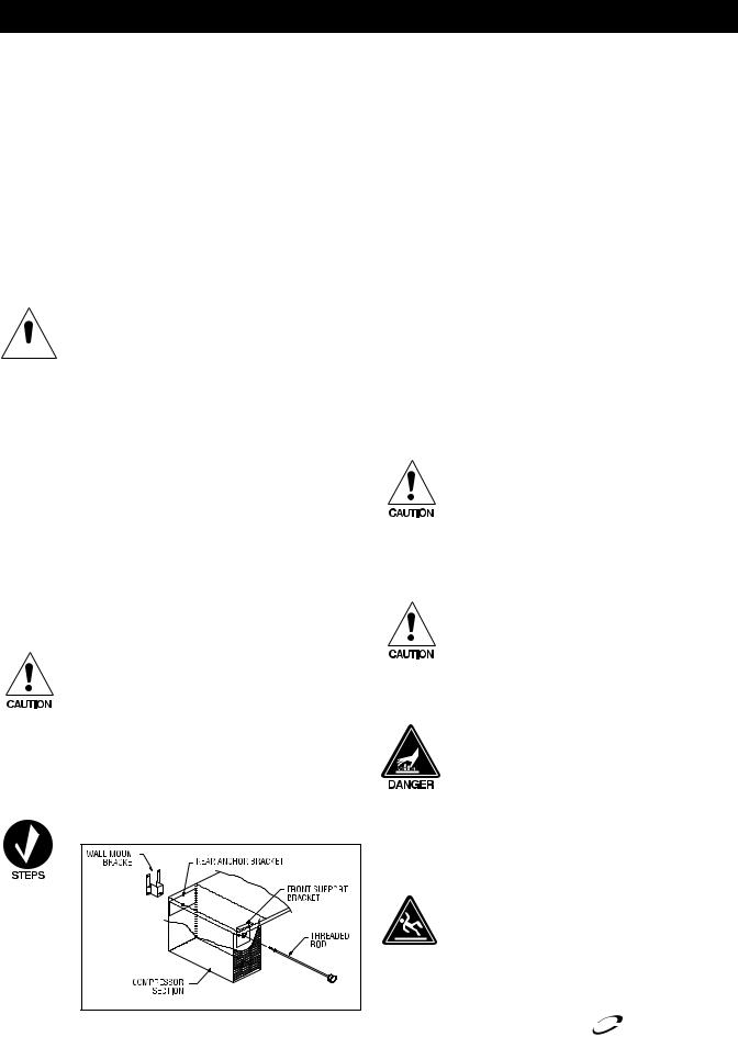
Wall bracket installation
A wall bracket kit is supplied to secure the equipment stand to an interior wall. Some models are supplied on optional casters. These units must also have the wall bracket installed during use.
The wall bracket must be installed properly and the equipment stand firmly secured to it before using this unit! Failure to observe this warning may result in damage to the equipment and/or injury to the operator! Never use the drawers as steps!
Do not overload the drawers or drop or throw product into the drawer pans.
To install the wall bracket, follow these instructions:
1.Place the threaded rod through the front and rear brackets in the compressor section. Thread the rod into
the wall bracket, making sure the longer bracket tabs are above the height of the unit.
2.Tighten the rod until the bracket is held snug against the back of the unit.
3.Move the unit against the wall at the desired location.
4.Secure the wall mount bracket to the wall using the top two holes provided in the bracket tabs exposed above the unit. The wall material must be capable of supporting a minimum load of 300 pounds (136 kilograms) in the vertical direction. All screws must be 1/4" diameter and be capable of transferring the load from the bracket to the wall.
5.Remove the threaded rod from the wall mount bracket and move the unit away from the wall, leaving the bracket attached to the wall.
6.Secure the bracket to the wall using the remaining four holes.
7.Move the unit back into place and thread the rod back into the wall mount bracket.
8.The unit should now be secured to the wall. Test the mounting by pulling on the unit and checking that all screws are tightened and the unit is firmly in place. If the unit is secured, you may now place other equipment on top of the stand and use the unit as required.
Never place any equipment on top of this unit without first installing the wall bracket as shown above and ensuring that the equipment is securely anchored and stable.
9.To remove the unit in order to clean behind it, first remove any equipment placed on top of the stand. Then rotate the knob on the threaded rod counterclockwise to loosen and remove the rod from the bracket.
Before removing any cooking equipment (including cooking oils) from the equipment stand, allow time for the equipment to cool thoroughly. Use extreme care in moving cooking equipment.
The threaded rod must be reinstalled and tightened before returning the unit to service!
Be sure all cooking equipment resting on the equipment stand is properly anchored. Consult the manufacturer’s instructions for the cooking equipment to determine the proper mounting technique. It is the owner’s and operator’s responsibility to securely anchor cooking equipment to the equipment stand.
Plumbing
Self-contained equipment stands come standard with a condensate evaporator. If the condensate evaporator fails, the unit’s drain must have an outlet to an appropriate drainage area or container.
|
Moisture collecting from improper drainage can create a |
|
slippery surface on the floor and a hazard to employees. |
|
It is the owner’s and operator’s responsibility to provide |
CAUTION |
a container or outlet for drainage. |
|
6 |
For customer service, call (800) 733-8829, (800) 733-8821, Fax (989) 773-3210, www.delfield.com |
Delfield® |
|
|
™ |
Installation — Continued
Electrical connection
Refer to the amperage data on page 3 & 4, the serial tag, your local code or the National Electrical Code to be sure the unit is connected to the proper power source. A protected circuit of the correct voltage and amperage must be run for connection of the line cord, or permanent connection to the unit.
F2000/F17 Series Equipment Stand Service and Installation Manual
The on/off switch must be turned to OFF and the unit disconnected from the power source whenever performing service, maintenance functions or cleaning the refrigerated area.
Under no circumstances is a self-contained unit to be operated without the louvered panel in place.
Operation: Refrigerated Base Equipment Stands
Drawer base equipment stands are designed and pre-set at the factory to maintain a temperature of 36°F to 40°F (2°C to 4°C). A solar-powered digital thermometer is located on the front of the unit to allow monitoring of the drawer housing temperature.
The drawer housing temperature is controlled by a thermostat located in the machine compartment. Continuous opening and closing of the drawers will hamper the unit’s ability to maintain optimum refrigeration temperature. Excess weight on top of the unit will adversely affect the operation of the drawers.
The cooling coil is coated in epoxy to provide long-lasting service. However, storing all acidic items, such as peppers and tomatoes with lids that are sealable and immediately wiping up all spills of either acid or base items will greatly extend the life of your unit.
Never stand on the unit or its drawers! They are not designed to hold the weight of an adult, and may collapse or unit may tip if misused in this manner.
Refrigerator Evaporator Fan Operation
When the refrigerator is initially powered up or immediately following a power outage the unit will begin cooling after a 3-6 minute delay. During normal operation the evaporator fan pulses independently of the compressor as dictated by the controller as follows:
1.During the cooling mode, compressor and evaporator fan run simultaneously.
2.During the compressor off mode, evaporator fan pulses three minutes on and three minutes off.
3.During an actual defrost event other than the off-cycle defrost, compressor stays off but the evaporator fan runs continuously.
|
Cooling Cycle |
|
Defrost Cycle |
||
|
|
|
|
|
|
Compressor On |
Compressor Off |
Compressor Off |
|||
|
|
|
|
|
|
Evap Fan |
Evap Fan |
Evap Fan |
Evap Fan |
Evap Fan |
Evap Fan |
On |
Off |
On |
Off |
On |
Off |
|
|
|
|
|
|
X |
|
Cycles On 3-Min, Off |
X |
|
|
|
3-Min |
|
|||
|
|
|
|
||
|
|
|
|
|
|
Operation: Freezer Base Equipment Stands
Freezer base equipment stands are designed and pre-set at the factory to maintain a temperature of 0°F to -5°F (-18°C to -21°C) interior cabinet temperature at 100°F (38°C) ambient room temperature. Self-contained units have a digital thermometer installed in the removable louver. The digital thermometer for
remote units is located in the removable access panel.
Freezer Evaporator Fan Operation
The evaporator fan(s) and condenser fan will cycle off and on with the compressor to conserve energy. The temperature control will cycle the compressor and condenser fan motor and evaporator fan motor to maintain box temperature at the control setting.
|
Cooling Cycle |
|
Defrost Cycle |
||
|
|
|
|
|
|
Compressor On |
Compressor Off |
Compressor Off |
|||
Evap Fan |
Evap Fan |
Evap Fan |
Evap Fan |
Evap Fan |
Evap Fan |
On |
Off |
On |
Off |
On |
Off |
X |
|
|
X |
|
X |
|
|
|
|
|
|
Freezer Defrost
Self-contained models use hot gas to defrost the evaporator coils. Remote freezers use electric defrost.
Delfield® |
For customer service, call (800) 733-8829, (800) 733-8821, Fax (989) 773-3210, www.delfield.com |
7 |
™ |
|
|
F2000/F17 Series Equipment Stand Service and Installation Manual
Temperature Control Settings, Self Contained Refrigerators And Freezers
A thermostat controls temperature in self contained refrigerators and freezers. Thermostats are located in the machine compartment. They are field adjustable and do not require a service agent. The factory setting for refrigerators is 2.5. The factory setting for freezers is 4.5. Set toward 1 for higher temperatures and toward 7 for lower temperatures.
Please make small incremental adjustments if a temperature adjustment is necessary. Contact the service department at Delfield +1 (989) 7737981 or your local service agent for additional assistance. Delfield is not responsible for charges incurred while adjusting the thermostat.
Temperature Control Settings, Remote Freezers
The temperature control is located in the machine compartment. It is field adjustable and does not require a service agent. The factory setting for a remote freezer is 0°F cut-in with a 5°F differential.
Please make small incremental adjustments if a temperature adjustment is necessary. Contact the service department at Delfield +1 (989) 7737981 or your local service agent for additional assistance. Delfield is not responsible for charges incurred while adjusting the thermostat.
Maximum Cooking Equipment Weight Capacity
Model |
Total Weight |
Unit Weight |
Total Drawer Capacity |
Max Cooking Equipment |
|
Weight |
|||||
|
|
|
|
||
|
|
|
|
|
|
F2952C |
1000lbs/ 454kg |
398lbs/ 181kg |
150lbs/ 68kg |
452lbs/ 205kg |
|
|
|
|
|
|
|
F2956C |
1000lbs/ 454kg |
405lbs/ 184kg |
150lbs/ 68kg |
445lbs/ 202kg |
|
|
|
|
|
|
|
F2962C |
1500lbs/ 680kg |
479lbs/ 217kg |
300lbs/ 136kg |
721lbs/ 327kg |
|
|
|
|
|
|
|
F2975C |
1500lbs/ 680kg |
540lbs/ 245kg |
300lbs/ 136kg |
660lbs/ 299kg |
|
|
|
|
|
|
|
F2980C |
1500lbs/ 680kg |
578lbs/ 262kg |
300lbs/ 136kg |
622lbs/ 282kg |
|
|
|
|
|
|
|
F2987C |
1500lbs/ 680kg |
672lbs/ 305kg |
450lbs/ 204kg |
378lbs/ 171kg |
|
|
|
|
|
|
|
F2999C |
1500lbs/ 680kg |
691lbs/ 313kg |
450lbs/ 204kg |
359lbs/ 163kg |
|
|
|
|
|
|
|
F29110C |
1800lbs/ 816kg |
766lbs/ 347kg |
450lbs/ 204kg |
584lbs/ 265kg |
|
|
|
|
|
|
|
F2660C |
1500lbs/ 680kg |
418lbs/ 190kg |
150lbs/ 68kg |
932lbs/ 423kg |
|
|
|
|
|
|
|
F2694C |
1500lbs/ 680kg |
500lbs/ 227kg |
300lbs/ 136kg |
700lbs/ 318kg |
|
|
|
|
|
|
8 |
For customer service, call (800) 733-8829, (800) 733-8821, Fax (989) 773-3210, www.delfield.com |
Delfield® |
|
|
™ |
Maintenance
Door Gasket Maintenance
Door gaskets require regular cleaning to prevent mold and mildew build up and also to retain the elasticity of the gasket. Gasket cleaning can be done with the use of warm soapy water. Avoid full strength cleaning products on gaskets as this can cause them to become brittle and crack. Never use sharp tools or knives to scrape or clean the gasket. Gaskets can be easily replaced and do not require the use of tools or an authorized service person. The gaskets are “Dart” style and can be pulled out of the groove in the door and new gaskets can be “pressed” back into place.
Drain Maintenance - Base
Each unit has a drain located inside the unit that removes the condensation from the evaporator coil and routes it to an external condensate evaporator pan. Each drain can become loose or disconnected during normal use. If you notice water accumulation on the inside of the unit be sure the drain tube is connected to the evaporator drain pan. If water is collecting underneath the unit make sure the end of the drain tube is in the condensate evaporator in the machine compartment. The leveling of the unit is important as the units are designed to drain properly when level. Be sure all drain lines are free of obstructions.
Drawer Maintenance Drawer Assembly Cleaning
The drawer assembly is designed to be cleaned easily. Both drawer and tracks are removable without tools. The drawer tracks are dishwasher safe or can be cleaned in a sink with detergents and a soft bristle brush. Drawers and tracks should be cleaned on a weekly basis.
Remove Drawers
Pull the drawer box out until it stops. Lift up on the drawer front and pull the drawer box completely out. Using a soft bristle brush, clean the track on the bottom of the drawer box. When finished, it should be wiped clean of all food and debris.
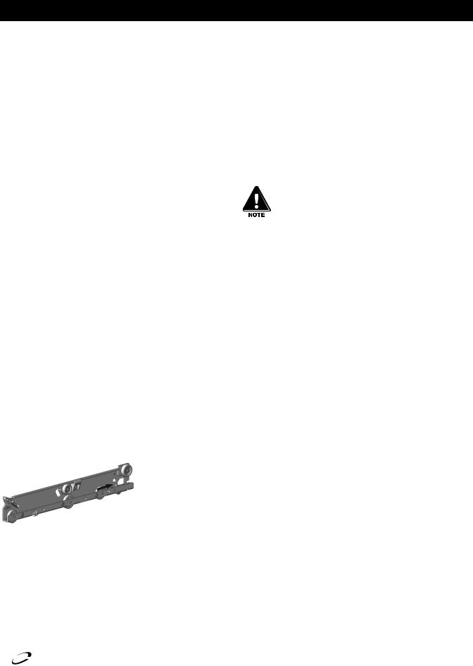
Tracks
The drawer box assembly must be removed. Pull the drawer tracks out until they hit a stop. Locate blue safety clips towards the back of each drawer track. Blue safety clips have a tab on the top. Push the tab back until it clicks. Lift up and pull the drawer tracks all the way out of the drawer cage. The drawer tracks are dishwasher safe or can be cleaned in a sink with detergents and a soft bristle brush. Drawers and tracks should be cleaned on a weekly basis.
Using a soft bristle brush, wash the track making sure each roller is thoroughly cleaned. The drawer cage should be cleaned with a soft bristle brush, removing any food and debris gathered on the bottom ledge. Once it’s cleaned thoroughly with a soft bristle brush, wipe remaining debris clean with a soft towel.
F2000/F17 Series Equipment Stand Service and Installation Manual
Reassembly
Push the drawer tracks into the drawer cage. The blue safety clip must remain pushed towards the back. Lift up and slide the drawer track all the way into the drawer cage. The blue safety clip will lock in place automatically. Once all tracks are replaced, insert the drawer box. Rest the drawer box bottom track on the front track roller. Then push the drawer back in place SLOWLY. When the drawer box is about half way in you will hit a STOP. You must lift the front of the drawer up approximately ½” (1.3cm) to continue inward. Clean tracks as often as possible. The cleaner the tracks are the better they will operate.
Caster Maintenance
Wipe casters with a damp cloth monthly to prevent corrosion.
The power switch must be turned to OFF and the unit disconnected from the power source whenever performing service, maintenance functions or cleaning the refrigerated area.
Refrigerators and Freezers
The interior and exterior can be cleaned using soap and warm water. If this isn’t sufficient, try ammonia and water or a nonabrasive liquid cleaner. When cleaning the exterior, always rub with the “grain” of the stainless steel to avoid marring the finish. Do not use an abrasive cleaner because it will scratch the stainless steel and can damage the breaker strips and gaskets.
Stainless Steel Care and Cleaning
To prevent discoloration or rust on stainless steel several important steps need to be taken. First, we need to understand the properties of stainless steel. Stainless steel contains 7080% iron, which will rust. It also contains 12-30% chromium, which forms an invisible passive film over the steel’s surface, which acts as a shield against corrosion. As long as the protective layer is intact, the metal is still stainless. If the film is broken or contaminated, outside elements can begin to breakdown the steel and begin to form discoloration or rust. Proper cleaning of stainless steel requires soft cloths or plastic scouring pads.
NEVER USE STEEL PADS, WIRE BRUSHES OR SCRAPERS!
Cleaning solutions need to be alkaline based or non-chloride cleaners. Any cleaner containing chlorides will damage the protective film of the stainless steel. Chlorides are also commonly found in hard water, salts, and household and industrial cleaners. If cleaners containing chlorides are used be sure to rinse repeatedly and dry thoroughly. Routine cleaning of stainless steel can be done with soap and water. Extreme stains or grease should be cleaned with a non-abrasive cleaner and plastic scrub pad. Always rub with the grain of the steel. There are stainless steel cleaners available which can restore and preserve the finish of the steels protective layer. Early signs of stainless steel breakdown are small pits and cracks. If this has begun, clean thoroughly and start to apply stainless steel cleaners in attempt to restore the passivity of the steel.
Delfield® |
For customer service, call (800) 733-8829, (800) 733-8821, Fax (989) 773-3210, www.delfield.com |
9 |
™ |
|
|
 Loading...