


Delfield N225, N227, N225L, N227L, 203 Service Manual
...
 Delfield™ ®
200 & 300 SERIES
Service and Installation Manual
Please read this manual completely before attempting to install or operate this equipment! Notify carrier of damage! Inspect all components immediately. See page 2.
Drop In and Undercounter Products
CAUTION
IMPORTANT |
INFORMATION |
|||||
|
|
USE |
||||
|
READ |
BEFORE |
|
|||
|
|
|
INSTRUCTIONS! |
|||
|
SAVE |
THESE |
||||
PLEASE |
|
|
||||
|
|
|
|
|
||
|
|
|
|
|
|
|
March 2009

200 and 300 Series Service and Installation Manual
Contents |
|
Serial Number Information......................................................... |
2 |
Receiving And Inspecting Equipment........................................ |
2 |
Specifications.............................................................................. |
2 |
Installation............................................................................... |
3-4 |
Operation.................................................................................... |
5 |
Maintenance................................................................................ |
5 |
Replacement Parts................................................................... |
6-8 |
Wiring Diagram........................................................................... |
8 |
Standard Labor Guidelines......................................................... |
9 |
Standard Warranty............................................................... |
10-11 |
Serial Number Information
Models |
Serial Tag Location |
N225, N227 |
On the compressor stand next to the temperature control |
203, 204, 204P, 248, 250, 305 |
On the bottom of the ice chests |
240 |
On the back |
242 |
On the bottom of the sink |
307 |
Underneath the top |
Always have the serial number of your unit available when calling for parts or service.
©2009 The Delfield Company. All rights reserved. Reproduction without written permission is prohibited. “Delfield” is a registered trademarks of The Delfield Company.
Receiving And Inspecting The Equipment
Even though most equipment is shipped packaged, care should be taken during unloading so the equipment is not damaged while being moved into the building.
1.Visually inspect the exterior of the package and skid or container. Any damage should be noted and reported to the delivering carrier immediately.
2.If damaged, open and inspect the contents with the carrier.
3.In the event that the exterior is not damaged, yet upon opening, there is concealed damage to the equipment
notify the carrier. Notification should be made verbally as well as in written form.
4.Request an inspection by the shipping company of the damaged equipment. This should be done within 10 days from receipt of the equipment.
5.Visually inspect the refrigeration package. Be sure lines are secure and base is still intact.
6.Freight carriers can supply the necessary damage forms upon request.
7.Retain all crating material until an inspection has been made or waived.
Specifications
MODEL |
|
L |
D |
H |
SHIP |
CUTOUT SIZE |
CABINET |
H.P. |
AMP |
VOLT |
NEMA |
DESIGN |
SYSTEM |
EVAP BTU/ |
|
|
|
|
|
WEIGHT |
|
CAPACITY |
|
|
|
PLUG |
LOAD BTU |
CAP. BTU |
TD/TEMP |
DROP-IN FREEZERS |
|
|
|
|
|
|
|
|
|
|
|
|
|
|
N225 |
|
16.56” |
27.87” |
26.75” |
115lbs |
25.75” x 14.62” |
6 gal. |
1/5 |
5.3 |
115 |
5-15P |
292 |
411 |
20/20°/-23° |
|
|
(42.1cm) |
(70.8cm) |
(67.9cm) |
(52kg) |
(65.4cm x 37.1cm) |
|
|
|
|
|
|
|
|
N227 |
|
30” |
27.87” |
26.75” |
191lbs |
25.75” x 28.00” |
12 gal. |
1/5 |
5.3 |
115 |
5-15P |
473 |
532 |
28/19°/-22 |
|
|
(76.2cm) |
(70.8cm) |
(67.9cm) |
(87kg) |
(65.4cm x 71.1cm) |
|
|
|
|
|
|
|
|
DROP-IN REEZERS WITH LEXAN® LID |
|
|
|
|
|
|
|
|
|
|
|
|
||
N225L |
|
16.56” |
27.87” |
26.75” |
115lbs |
25.75” x 14.62” |
6 gal. |
1/5 |
5.3 |
115 |
5-15P |
292 |
411 |
20/20°/-23° |
|
|
(42.1cm) |
(70.8cm) |
(67.9cm) |
(52kg) |
(65.4cm x 37.1cm) |
|
|
|
|
|
|
|
|
N227L |
|
30” |
27.87” |
26.75” |
191lbs |
25.75” x 28.00” |
12 gal. |
1/5 |
5.3 |
115 |
5-15P |
473 |
532 |
28/19°/-22 |
|
|
(76.2cm) |
(70.8cm) |
(67.9cm) |
(87kg) |
(65.4cm x 71.1cm) |
|
|
|
|
|
|
|
|
DROP-IN WATER STATIONS AND ICE STORAGE |
|
|
|
|
|
|
|
|
|
|
|
|||
203 |
ice chest |
20.25” |
20.25” |
23.25” |
52lbs |
19.25” x 19.25” |
90lbs |
N/A |
N/A |
N/A |
N/A |
N/A |
N/A |
N/A |
|
|
(51.4cm) |
(51.4cm) |
(59.1cm) |
(24kg) |
(48.9cm x 48.9cm) |
(41kg) |
|
|
|
|
|
|
|
204 |
water and ice |
24” |
21” |
23.5” |
47.5lbs |
21” x 17.75” |
45lbs |
N/A |
N/A |
N/A |
N/A |
N/A |
N/A |
N/A |
|
station |
(61.0cm) |
(53.3cm) |
(59.1cm) |
(22kg) |
(53.3cm x 45.1cm) |
(20kg) |
|
|
|
|
|
|
|
204P |
water and ice |
24” |
21” |
27” |
47.5lbs |
21” x 17.75” |
45lbs |
N/A |
N/A |
N/A |
N/A |
N/A |
N/A |
N/A |
|
station |
(61.0cm) |
(53.3cm) |
(68.6cm) |
(22kg) |
(53.3cm x 45.1cm) |
(20kg) |
|
|
|
|
|
|
|
240 |
ice chest with |
21” |
17.5” |
17” |
36lbs |
— |
75lbs |
N/A |
N/A |
N/A |
N/A |
N/A |
N/A |
N/A |
|
cover |
(53.3cm) |
(44.5cm) |
(43.2cm) |
(16kg) |
|
(34kg) |
|
|
|
|
|
|
|
248 |
water and ice |
31” |
15” |
22.5” |
28lbs |
28” x 12.5” |
45lbs |
N/A |
N/A |
N/A |
N/A |
N/A |
N/A |
N/A |
|
station |
(78.7cm) |
(38.1cm) |
(57.2cm) |
(13kg) |
(71.1cm x 31.8cm) |
(20kg) |
|
|
|
|
|
|
|
305 |
ice chest with |
21.25” |
15.25” |
13” |
18lbs |
12.5” x 17.75” |
45lbs |
N/A |
N/A |
N/A |
N/A |
N/A |
N/A |
N/A |
|
cover |
(54.0cm) |
(38.7cm) |
(33.0cm) |
(8kg) |
(31.8cm x 45.1cm) |
(20kg) |
|
|
|
|
|
|
|
307 |
glass filler |
12” |
12” |
9.5” |
7lbs |
9.00” x 9.00” |
— |
N/A |
N/A |
N/A |
N/A |
N/A |
N/A |
N/A |
|
|
(30.5cm) |
(30.5cm) |
(24.1cm) |
(3kg) |
(23cm x 23cm) |
|
|
|
|
|
|
|
|
UNDERCOUNTER SINKS, WATER STATIONS AND ICE STORAGE |
|
|
|
|
|
|
|
|
|
|||||
242 |
UC sink & faucet |
18” |
13.5” |
12.75” |
20lbs |
17” x 12.5” |
— |
N/A |
N/A |
N/A |
N/A |
N/A |
N/A |
N/A |
|
|
(45.7cm) |
(34.3cm) |
(32.4cm) |
(9kg) |
(43.2cm x 31.8cm) |
|
|
|
|
|
|
|
|
250 |
UC sink, ice chest |
46” |
14.12” |
22.75” |
81lbs |
45” x 13” |
45lbs |
N/A |
N/A |
N/A |
N/A |
N/A |
N/A |
N/A |
|
and water station |
(116.8cm) |
(35.9cm) |
(57.8cm) |
(37kg) |
(114.3cm x 33.0cm) |
(20kg) |
|
|
|
|
|
|
|
For customer service, call (800) 733-8829, (800) 733-8821, Fax (989) 773-3210, www.delfield.com |
Delfield® |
|
™ |
200 and 300 Series Service and Installation Manual
Installation - Models N225, N225L, N227 And N227L
Location
Units in this manual are intended for indoor use only. The refrigeration system has been factory tested and should require no further adjustment during installation.
For the most efficient refrigeration, be sure to provide good air circulation inside and outside the unit.
Outside Cabinet: Be sure that the unit has access to ample air. Avoid hot corners and locations near stoves and ovens.
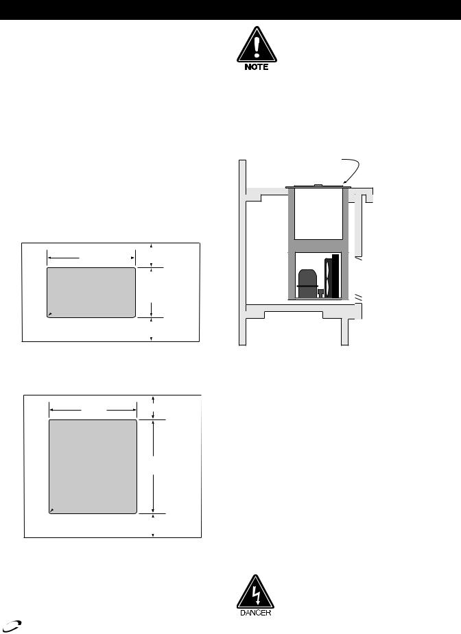
The louver provided must be installed in front of the condensing unit’s finned coil (see illustration 3). A second cutout must be made at the rear or end of the equipment to allow air flow through the unit. No louver is provided for the second cutout. Any restriction to the proper air flow, total or partial, will void the compressor warranty.
Counter Cutouts
For installation provide a cutout in the counter as shown (see illustration 1 or 2). The counter must be sturdy enough to hold the combined weight up to 300 pounds of the drop-in and the product stored inside.
|
25.75" |
|
|
|
|
|
|
1.00"/2.5cm (min.) |
|||
|
65.4cm |
|
|
||
|
|
|
|||
|
|
|
|||
.75"/1.9cm |
CUTOUT |
|
|
||
|
|
||||
|
|
14.62" |
|||
radius |
|
|
|
37.1cm |
|
|
|
|
COUNTERTOP |
1.00"/2.5cm (min.) |
|
|
|
|
Illustration 1. Model N225 & N225L cutout dimensions
25.75" |
1.00"/2.5cm (min.) |
65.4cm |
|
CUTOUT |
28.0" |
|
71.1cm |
.75"/1.9cm radius
N225 N225L N227 or N227L DROP-IN
 LOUVER
 13.00" x 25.00"
 33.0cm x 63.5cm
TYPICAL |
LOUVER CUTOUT SIZE |
12.00" x 23.50" |
|
COUNTER |
30.5cm x 59.7cm |
CABINET |
(typical installation) |
NOTE: A second cutout (without louver) must also be made to allow proper air flow.
Illustration 3. N225 N225L N227 & N227L louver installation
Electrical Connection
Refer to the amperage data on page 2, the serial tag, your local code or the National Electrical Code to be sure the unit is connected to the proper power source. A protected circuit of the correct voltage and amperage must be run for connection of the line cord.
|
|
|
COUNTERTOP |
1.00"/2.5cm (min.) |
|
|
|
|
Illustration 2. Model N227 & N227L cutout dimensions
If the unit does not operate after it is plugged in, check the thermostat to see if it was inadvertently turned OFF during installation.
The unit must be disconnected from the power source whenever performing service or maintenance functions.
Delfield® |
For customer service, call (800) 733-8829, (800) 733-8821, Fax (989) 773-3210, www.delfield.com |
|
™ |
|
|
200 and 300 Series Service and Installation Manual
Installation - Models 203, 204, 204P, 240, 242, 248, 250, 305 And 307
Location
Units in this manual are intended for indoor use only.
Avoid hot corners and locations near stoves and ovens.
Counter Cutouts
For installation, provide a cutout in the counter sized according to the chart below. The counter must be sturdy enough to hold the combined weight up to 300 pounds of the drop-in and the product stored inside.
Model |
|
Cutout Size |
Mounting |
1/2” IPS |
Drain |
|
|
|
|
Studs |
Water |
|
|
|
|
|
|
Hookup |
|
|
203 |
ice chest |
19.25” x 19.25” |
N/A |
N/A |
(1) |
1” |
|
|
(48.9cm x 48.9cm) |
|
|
|
|
204 |
water and ice |
21” x 17.75” |
4 |
1 |
(2) |
1” |
|
station |
(53.3cm x 45.1cm) |
|
|
|
|
204P |
water and ice |
21” x 17.75” |
4 |
1 |
(2) |
1” |
|
station |
(53.3cm x 45.1cm) |
|
|
|
|
240 |
ice chest with cover |
N/A |
N/A |
N/A |
(1) |
1” |
242 |
UC sink & faucet |
17” x 12.5” |
N/A |
2 |
(1) |
1-1/2” |
|
|
(43.2cm x 31.8cm) |
|
|
|
|
248 |
water and ice |
28” x 12.5” |
4 |
1 |
(2) |
1” |
|
station |
(71.1cm x 31.8cm) |
|
|
|
|
250 |
UC sink, ice chest |
45” x 13” |
N/A |
3 |
(2) |
1” |
|
and water station |
(114.3cm x 33.0cm) |
|
|
(1) |
1-1/2” |
305 |
ice chest with cover |
12.5” x 17.75” |
4 |
N/A |
(1) |
1” |
|
|
(31.8cm x 45.1cm) |
|
|
|
|
307 |
glass filler |
9.00” x 9.00” |
4 |
1 |
(1) |
1” |
|
|
(23cm x 23cm) |
|
|
|
|
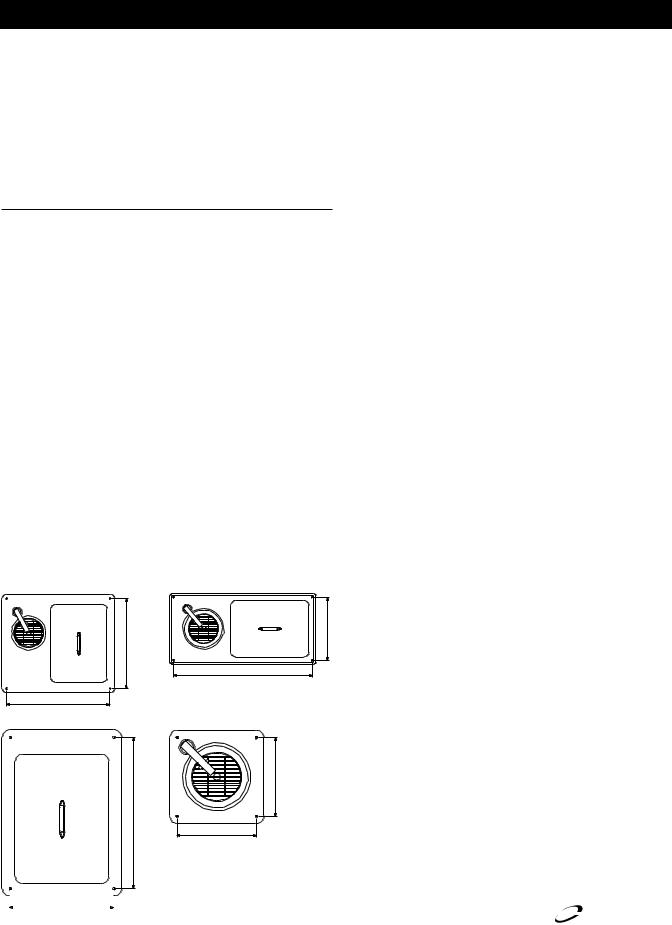
Mounting Studs
Equipment with mounting studs are pictured below. Mark the stud locations according to the measurements or place the equipment in the cutout to mark the stud locations. Drill 0.37” (1.0cm) diameter holes through the counter for the studs.
Drain
Provided 1” (2.5cm) drain, nut and washer must be field installed to an appropriate container or floor drain following local code requirements. Sinks come standard with 1-1/2” basket strainer assemblies.
Water Connection
All 1/2” (1.3cm) IPS water inlets must be field connected following local code requirements.
22.00” (55.9cm)
204/204P Stud Location
<![endif]>19.25” (48.9cm) 204/204P Stud Location
| <![if ! IE]> <![endif]>13.50” (34.3cm) |
29.50” (74.9cm) |
248 Stud Location
<![endif]>19.375” (49.2cm) 305 Stud Location
<![endif]>10.12” (25.7cm) 307 Stud Location
10.12” (25.7cm)
307 Stud Location
|
|
|
|
|
|
|
|
|
13.25” (33.7cm) |
|
|
Delfield |
|
|
For customer |
service, call (800) 733-8829, (800) 733-8821, Fax (989) 773-3210, www.delfield.com |
|
|||
|
|
305 Stud Location |
|
|
™ |
® |
|
|
|
|
|
|
|
 Loading...