


 Delfield™ ®
Chili's
Service and Installation Manual
Please read this manual completely before attempting to install or operate this equipment! Notify carrier of damage! Inspect all components immediately. See page 2.
|
|
N |
|
IO |
|
UT |
|
|
CA |
|
|
Important |
Information |
|||||
|
|
Use |
||||
Read |
Before |
|
||||
These |
Instructions! |
|||||
|
Save |
|||||
Please |
|
|
||||
|
|
|
|
|||
|
|
|
|
|
||
June 2012
Chili's Service and Installation Manual
Contents |
|
Serial Number Location......................................................... |
2 |
Receiving And Inspecting...................................................... |
2 |
Specifications........................................................................ |
3 |
Wiring Diagram..................................................................... |
3 |
Installation............................................................................. |
4 |
Operation............................................................................... |
4 |
Cold Rail Timer Setup............................................................ |
5 |
Pressure Control Settings...................................................... |
5 |
Preventive Maintenance..................................................... |
6-7 |
Replacement Parts.......................................................... |
8-12 |
Standard Labor Guidelines.................................................. |
13 |
Warranties..................................................................... |
14-15 |
Serial Number Location
The serial number is located in the interior back top corner.
Always have the serial number of your unit available when calling for parts or service. A complete list of authorized Delfield parts depots is available at www.delfield.com
©2012 The Delfield Company. All rights reserved. Reproduction without written permission is prohibited. “Delfield” is a registered trademark of The Delfield Company.
Receiving And Inspecting The Equipment
Even though most equipment is shipped crated, care should be taken during unloading so the equipment is not damaged while being moved into the building.
1.Visually inspect the exterior of the package an skid or container. Any damage should be noted and reported to the delivering carrier immediately.
2.If damaged, open and inspect the contents with the carrier.
3.In the event that the exterior is not damaged, yet upon opening, there is concealed damage to the equipment notify the carrier. Notification should be made verbally as well as in written form.
4.Request an inspection of the concealed equipment. This should be done within 10 days from receipt of the equipment.
5.Check the lower portion of the unit to be sure casters are not bent.
6.Also remove the back and visually inspect the refrigeration
package. Be sure lines are secure and base is still intact.
7.Freight carriers can supply the necessary forms upon request.
8.Retain all crating material until an inspection has been made or waived.
Uncrating the Equipment
First cut and remove the banding from around the crate. Remove the front of the crate material, use of some tools will be required.
2 |
For customer service, call (800) 733-8829, (800) 773-8821, Fax (989) 773-3210, www.delfield.com |
Delfield® |
|
|
™ |
Chili's Service and Installation Manual
Specifications
SKU # |
Custom |
# of Doors |
Volume |
Shelf Area |
HP |
Volts/Hertz/ |
Amps |
BTU Load |
BTU Load |
Refg. 404a |
|
Model # |
Cu.Ft. |
Sq. Ft. |
Phase |
(Base) |
(Rail) |
Charge (oz.) |
|||||
|
|
|
|
||||||||
|
|
|
|
|
|
|
|
|
|
|
|
DCH-BLS-32R |
F18MC32-BI |
1 |
7.7 |
5.32 |
1/3 |
115/60/1 |
8.0 |
424 |
1058 |
24.0 |
|
|
|
|
|
|
|
|
|
|
|
|
|
DCH-BLSN-33L |
F18MC33-BI |
1 |
7.7 |
5.32 |
1/3 |
115/60/1 |
8.0 |
424 |
1058 |
24.0 |
|
DCH-BLSN-33R |
|
|
|
|
|
|
|
|
|
|
|
|
|
|
|
|
|
|
|
|
|
|
|
DCH-BS-27L |
F18MC27-BI |
1 |
6.3 |
4.36 |
1/3 |
115/60/1 |
8.0 |
424 |
1058 |
24.0 |
|
DCH-BS-27R |
|
|
|
|
|
|
|
|
|
|
|
|
|
|
|
|
|
|
|
|
|
|
|
DCH-BS-32L |
F18MC32-BI |
1 |
7.7 |
5.32 |
1/3 |
115/60/1 |
8.0 |
424 |
1058 |
24.0 |
|
|
|
|
|
|
|
|
|
|
|
|
|
DCH-BSN-27L |
F18MC27-BI |
1 |
6.3 |
4.36 |
1/3 |
115/60/1 |
8.0 |
424 |
1058 |
24.0 |
|
DCH-BSN-27R |
|
|
|
|
|
|
|
|
|
|
|
|
|
|
|
|
|
|
|
|
|
|
|
DCH-BSN-32L |
F18MC32-BI |
1 |
7.7 |
5.32 |
1/3 |
115/60/1 |
8.0 |
424 |
1058 |
24.0 |
|
DCH-BSN-32R |
|
|
|
|
|
|
|
|
|
|
|
|
|
|
|
|
|
|
|
|
|
|
|
DCH-DC-27L |
F18MC27-BI |
1 |
6.3 |
4.36 |
1/3 |
115/60/1 |
8.0 |
424 |
1058 |
24.0 |
|
DCH-DC-27R |
|
|
|
|
|
|
|
|
|
|
|
|
|
|
|
|
|
|
|
|
|
|
|
DCH-FS-27L |
F18MC27-BI |
1 |
6.3 |
4.36 |
1/3 |
115/60/1 |
8.0 |
424 |
1058 |
24.0 |
|
DCH-FS-27R |
|
|
|
|
|
|
|
|
|
|
|
|
|
|
|
|
|
|
|
|
|
|
|
DCH-FS-32L |
F18MC32-BI |
1 |
7.7 |
5.32 |
1/3 |
115/60/1 |
8.0 |
424 |
1058 |
24.0 |
|
DCH-FS-32R |
|
|
|
|
|
|
|
|
|
|
|
|
|
|
|
|
|
|
|
|
|
|
|
DCH-FSN-27L |
F18MC27-BI |
1 |
6.3 |
4.36 |
1/3 |
115/60/1 |
8.0 |
424 |
1058 |
24.0 |
|
DCH-FSN-27R |
|
|
|
|
|
|
|
|
|
|
|
|
|
|
|
|
|
|
|
|
|
|
|
DCH-FSN-27DRW |
F18MC27-BI |
2 Drawers |
6.3 |
NA |
1/3 |
115/60/1 |
8.0 |
424 |
1058 |
24.0 |
|
|
|
|
|
|
|
|
|
|
|
|
|
DCH-FSN-33L |
F18MC33-BI |
1 |
7.7 |
5.32 |
1/3 |
115/60/1 |
8.0 |
424 |
1058 |
24.0 |
|
DCH-FSN-33R |
|
|
|
|
|
|
|
|
|
|
|
|
|
|
|
|
|
|
|
|
|
|
|
DCH-SCS-33L |
F18MC33-BI |
1 |
7.7 |
5.32 |
1/3 |
115/60/1 |
8.0 |
424 |
1058 |
24.0 |
|
DCH-SCS-33R |
|
|
|
|
|
|
|
|
|
|
|
|
|
|
|
|
|
|
|
|
|
|
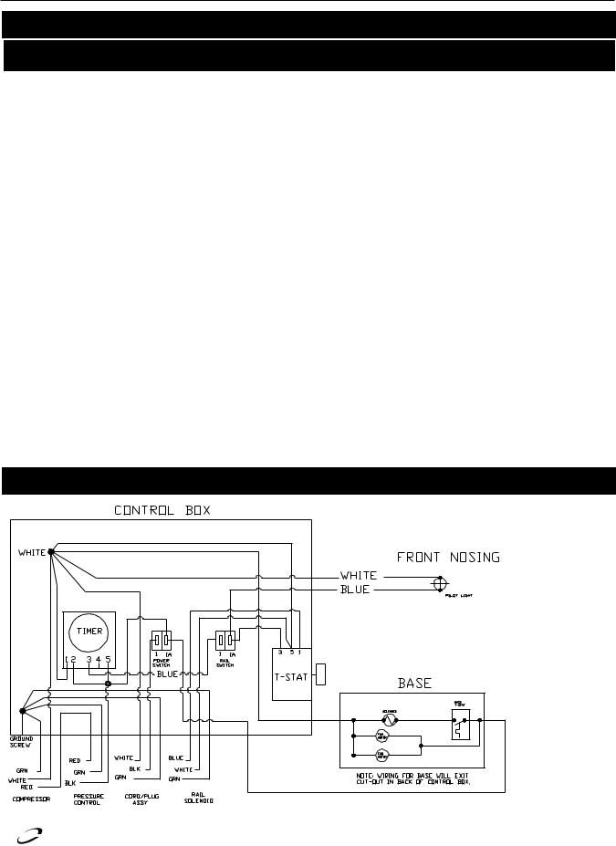
Wiring Diagram
™ |
|
|
Delfield® |
For customer service, call (800) 733-8829, (800) 773-8821, Fax (989) 773-3210, www.delfield.com |
3 |
Chili's Service and Installation Manual
Installation
Location
Be sure the location chosen has a floor strong enough to support the total weight of the cabinet and contents. A fully loaded model may weigh as much as 500 pounds! Reinforce the floor as necessary to provide for maximum loading.
It is very important to allow for proper air flow, both inside and outside.
Avoid hot corners and locations near stoves, ovens and other pieces of cooking equipment.
It is recommended that the unit be installed no closer than 1” from any wall. Do not install the unit near any combustible material or object
affected by heat or moisture.
Leveling
A level cabinet looks better and will perform better because the drain pan will drain properly, the doors will line up with the frames properly, and the cabinet will not be subject to undue strain.
A unit on casters will not be adjustable. Be sure the unit is on a level floor, make necessary changes to the floor for proper level.
Plumbing
Self-contained models are standard with a condensate evaporator. If, for some reason a unit does not have a condensate evaporator, or if the evaporator fails, the unit’s drain must have an outlet to an appropriate drainage area or container.
Moisture collecting from improper drainage can create a slippery surface on the floor and a hazard to employees. It is the owner’s and operator’s
CAUTION responsibility to provide a container or outlet for drainage.
Electrical connection
Refer to the amperage data on pages 3, the serial tag, your local code or the National Electrical Code to be sure the unit is connected to the proper power source. A protected circuit of the correct voltage and amperage must be run for connection of the line cord, or permanent connection of the unit.
Self-contained units with a cord and plug have an ON/OFF switch located on the back of the equipment. Simply turn the switch to ON to begin operation.
The power switch must be turned to OFF and the unit disconnected from the power source whenever performing service or maintenance
functions.
Never operate the unit without the louvered panel in place!
Operation
After turning the ON/OFF switch to ON the unit’s compressor will begin operating. Delfield refrigerated bases are designed to maintain an operational temperature of 36°F to 40°F. Temperature in the salad top and refrigerated rail opening is 33°F to 41°F.
Do not place hot pans on/against the blue ABS liner. Do not throw items into the storage area. Failure to heed these recommendations could result in
damage to the interior of the cabinet or to the blower coil.
Overloading the storage area, restricting the air flow, and continuous opening and closing of the doors will hamper the units ability to maintain operational temperature.
Refrigerated rail units
To ensure product quality in the rail it is recommended that product be rotated every four hours. Product in the rail must be removed and stored in the refrigerated base at the end of
the day. When the timer is set, the rail will turn off at night and on again in the morning. This will save energy, allow the rail time to defrost and maintain product quality. The LiquiTec rail is required to be shut off at night, there is a rail ON/OFF
switch to be used if necessary. A pilot light on front of the
unit will illuminate when the rail is on. With a LiquiTec rail a thermostat is provided to maintain rail temperature. To adjust for colder temperatures, turn the knob clockwise. For warmer temperatures, turn the knob counter-clockwise. Never turn the knob more than 1 dial number and always allow 8 hours for temperature stabilization before making additional adjustments.
The rail cover must not be removed during rail operation. Any attempt to modify the rail could result in operator injury.
If adding any item to the unit, be sure to keep in mind the location of the refrigeration lines on wrapped rail units. A refrigeration leak in a rail is extremely difficult and costly to repair. In some cases it cannot be repaired at all.
4 |
For customer service, call (800) 733-8829, (800) 773-8821, Fax (989) 773-3210, www.delfield.com |
Delfield® |
|
|
™ |

Chili's Service and Installation Manual
Cold Rail Timer Setup
Timer is located 

 on back of unit.
Cold Rail Timer
Base Switch
Cold Rail Power Switch
After installing the unit, find the timer located on back of the unit. See graphic above. Set the Cold Rail timer to the correct local time. Turn the rail switch ON. The defrost period is factory set to standard Brinker International specifications (OFF at 12:00 a.m., ON at 8:30 a.m.). A pilot light on front of the unit will illuminate when the rail is on.
High ambient temperature, humidity, or a rail that does not have a full compliment of pans can cause
excessive frost in the rail.
Remove any water remaining in the cold rail during early morning operations. Cold rails should be cleaned at this time when the frost/ice is not present. Rail performance will be significantly reduced if water remains in rail and is allowed to freeze.
If there is excessive frost upon morning startup, call Delfield customer service.
Pressure Control Settings
Factory recommended low-pressure control settings are:
HFC-404A refrigerators with LiquiTec Rail:
20# cut-in and 10# cut-out to Differential setting of 10#
Pressure control settings are measured in pounds, not fahrenheit.
Delfield® |
For customer service, call (800) 733-8829, (800) 773-8821, Fax (989) 773-3210, www.delfield.com |
5 |
™ |
|
|
 Loading...