


Data sheet
Actuator for modulating control
AME 140X - with feedback signal
Description |
|
AME 140X actuator are suitable to operate with |
|
|
|||
|
|
VZ or VZL valves whenever feedback signal is |
|
|
|
required. The actuator can be used in fan coil |
|
|
|
units, induction units, small reheaters, recoolers, |
|
|
|
and zone applications in which hot/cold water is |
|
|
|
the controlled medium. |
|
|
|
Main data: |
|
|
|
• |
Modulating control (Y) |
|
|
• |
Feedback (X) signal |
|
|
• Force switch-off at stem down position |
|
|
|
|
prevents overload of actuator and valve. |
|
|
• No tools required for mounting |
|
|
|
• Maintenance free during lifetime |
|
|
|
• |
Low noise operation |
|
|
• Self-positioning process |
|
|
|
• Supplied with 1,5 m cable |
|
|
|
||
Ordering |
|
|
|
|
|
Type |
Supply |
Speed |
Code No. |
|
|
|
voltage |
|
|||
|
|
|
|
|
|
|
AME 140X |
24 V~ |
12 s/mm |
082H8065 |
|
|
|
|
|
|
|
Technical data
Power supply |
|
V |
24; ±20%; AC |
|
Power consumption |
running |
VA |
1,5 |
|
standby |
W |
1,0 |
||
|
||||
Frequency |
|
Hz |
50/60 |
|
Control input Y |
|
V |
0-10(2-10); Ri=200 kΩ |
|
|
mA |
0-20(4-20; Ri=500 Ω |
||
|
|
|||
Control output X |
|
V |
0-10(2-10); Ro(min)=38 kΩ |
|
Closing force |
|
N |
200 |
|
Max. stroke |
|
mm |
5,5 |
|
Speed |
|
s/mm |
12 |
|
Max. medium temperature |
|
|
130 |
|
Ambient temperature |
|
°C |
0 … 55 |
|
Storage and transport temperature |
|
–40 … 70 |
||
Protection class |
|
|
III safety extra-low voltage |
|
Grade of enclosure |
|
|
IP 42 |
|
Weight |
|
kg |
0,3 |
|
-markinginaccordancewithstandards |
Low Voltage Directive 2006/95/EC, EN 60730-1, EN 60730-2-14 |
|||
EMC Directive 2004/108/EEC, EN 61000-6-1, EN 61000-6-3 |
||||
|
|
|
||
DEN-SMT/SI |
VD.IR.A1.02 © Danfoss 07/2013 |
1 |
Data sheet
Data sheet |
Actuators for modulating control AME 140X |
||||||||||||||||||||||||||
|
|
|
|
|
|
|
|
|
|
|
|
|
|
|
|
|
|
|
|
|
|
|
|
|
|
|
|
Installation |
Mechanical |
|
|
|
|
|
|
|
|
|
|
|
|
|
|
|
|
|
|
|
|
|
|
||||
|
|
|
|
|
|
|
|
|
|
|
|
|
|
|
|
|
|
|
|
|
|
||||||
|
|
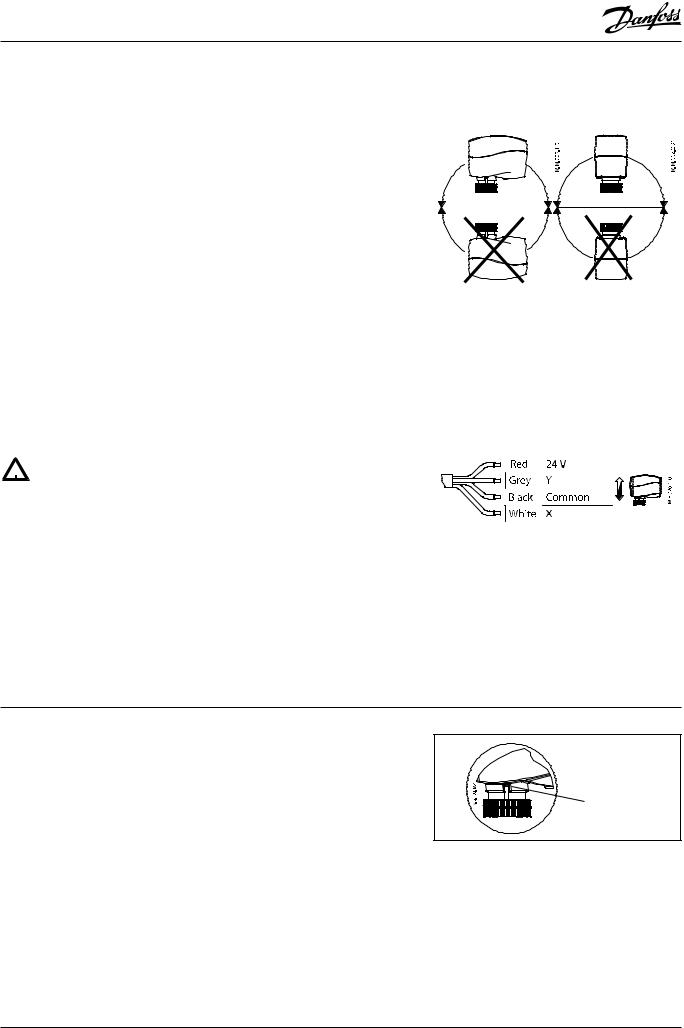
The actuator should be mounted with the valve |
|
|
|
|
|
|
|
|
|
|
|
|
|
|
|
|
|
|
|
|
|||||
|
|
stem in either horizontal position or pointing |
|
|
|
|
|
|
|
|
|
|
|
|
|
|
|
|
|
|
|
|
|||||
|
|
upwards. |
|
|
|
|
|
|
|
|
|
|
|
|
|
|
|
|
|
|
|
|
|
|
|
|
|
|
|
The actuator is fixed to the valve body by means |
|
|
|
|
|
|
|
|
|
|
|
|
|
|
|
|
|
|
|
|
|||||
|
|
of a mounting ring which requires no tools for |
|
|
|
|
|
|
|
|
|
|
|
|
|
|
|
|
|
|
|
|
|||||
|
|
mounting. The ring should be tightened by hand. |
|
|
|
|
|
|
|
|
|
|
|
|
|
|
|
|
|
|
|
|
|||||
|
|
|
|
|
|
|
|
|
|
|
|
|
|
|
|
|
|
|
|
|
|
||||||
|
|
Electrical |
|
|
|
|
|
|
|
|
|
|
|
|
|
|
|
|
|
|
|
|
|
|
|
|
|
|
|
|
|
|
|
|
|
|
|
|
|
|
|
|
|
|
|
|
|
|
|
|
|
|
|
||
|
|
Important: It is strongly recommended that the |
|
|
|
|
|
|
|
|
|
|
|
|
|
|
|
|
|
|
|
|
|||||
|
|
mechanical installation is completed before the |
|
|
|
|
|
|
|
|
|
|
|
|
|
|
|
|
|
|
|
|
|||||
|
|
electrical installation. |
|
|
|
|
|
|
|
|
|
|
|
|
|
|
|
|
|
|
|
|
|
|
|||
|
|
Each actuator is supplied with the connecting |
|
|
|
|
|
|
|
|
|
|
|
|
|
|
|
|
|
|
|
|
|||||
|
|
cable for the controller. |
|
|
|
|
|
|
|
|
|
|
|
|
|
|
|
|
|
|
|
|
|||||
|
|
|
|
|
|
|
|
|
|
|
|
|
|
|
|
|
|
|
|
|
|
|
|
|
|
|
|
Disposal |
The actuator must be dismantled and the |
||||||||||||||||||||||||||
|
|
elements sorted into various material groups |
|||||||||||||||||||||||||
|
|
before disposal. |
|
|
|
|
|
|
|
|
|
|
|
|
|
|
|
|
|
|
|
|
|
|
|||
|
|
|
|
|
|
|
|
|
|
|
|
|
|
|
|
|
|
|
|
|
|
|
|
|
|
|
|
Wiring |
|
|
|
|
|
|
|
|
|
|
|
|
|
|
|
|
|
|
|
|
|
|
|
|
|
||
Y |
|
V |
|
0-10(2-10); Ri=200 kΩ |
|
|
|
|
|
|
|
|
|
|
|
|
|
|
|
|
|
|
|
|
|
||
|
|
|
|
mA |
|
0-20(4-20; Ri=500 Ω |
|
|
|
|
|
|
|
|
|
|
|
|
|
|
|
|
|
|
|
|
|
AC 24 V |
X |
|
V |
|
0-10(2-10); Ro(min)=38 kΩ |
|
|
|
|
|
|
|
|
|
|
|
|
|
|
|
|
|
|
|
|
|
|
|
|
|
|
|
|
|
|
|
|
|
|
|
|
|
|
|
|
|
|
|
|
|
|
|
|
||
|
|
|
|
|
|
|
|
|
|
|
|
|
|
|
|
|
|
|
|
|
|
|
|
|
|
||
Connect via safety isolating |
|
|
|
|
|
|
|
|
|
|
|
|
|
|
|
|
|
|
|
|
|
|
|
|
|
|
|
|
|
|
|
|
|
|
|
|
|
|
|
|
|
|
|
|
|
|
|
|
|
|
|
|
|
||
transformer. |
|
|
|
|
|
|
|
|
|
|
|
|
|
|
|
|
|
|
|
|
|
|
|
|
|
|
|
|
|
|
|
|
|
|
|
|
|
|
|
|
|
|
|
|
|
|
|
|
|
|
|
|
|
||
|
|
|
|
|
|
|
|
|
|
|
|
|
|
|
|
|
|
|
|
|
|
|
|
|
|
||
|
|
|
|
|
|
|
|
|
|
|
|
|
|
|
|
|
|
|
|
|
|
|
|
|
|
|
|
Commissioning |
The factory setting of the spindle is the fully |
|
stem up position because of easier mechanical |
|
connection of the actuator on the valve. |
|
Actuator should be first mechanically connected |
|
to the valve because it starts automatically |
|
with self stroking procedure when first time |
|
connected to power supply. |
Do not manually operate the drive if power is connected!
Do not dismount the actuator from the valve when it is in a stem down position!
If dismounted in a stem down position, there is a high risk that the actuator gets stuck.
Installation procedure |
1. |
Check the valve’s neck. The actuator should |
|
|
be in steam up position (factory setting). |
|
|
Ensure that the actuator is mounted |
|
|
securely on valve body. |
|
2. |
Energise the actuator according to the wiring |
|
|
diagram - see wiring. |
|
3. |
The direction of stem movement can be |
|
|
observed on the position indicator. |
Auto sleep mode
1.If actuator is not mounted to the valve but connected to the power supply, it will first run to its extracted end position (buzz noise from the motor will appear). This behavior will last for max 3 minutes when power supply will be automatically cut off from electro motor and
LED indicators.
position indicator
2.It is mandatory to drive the spindle of the actuator to upper position before it will be installed on valve (please refer to manual override drawings)!
3.Auto sleep mode switches back to learning mode by pressing RESET button or by cycling power supply.
2 |
VD.IR.A1.02 © Danfoss 07/2013 |
DEN-SMT/SI
Data sheet |
Actuators for modulating control AME 140X |
|
|
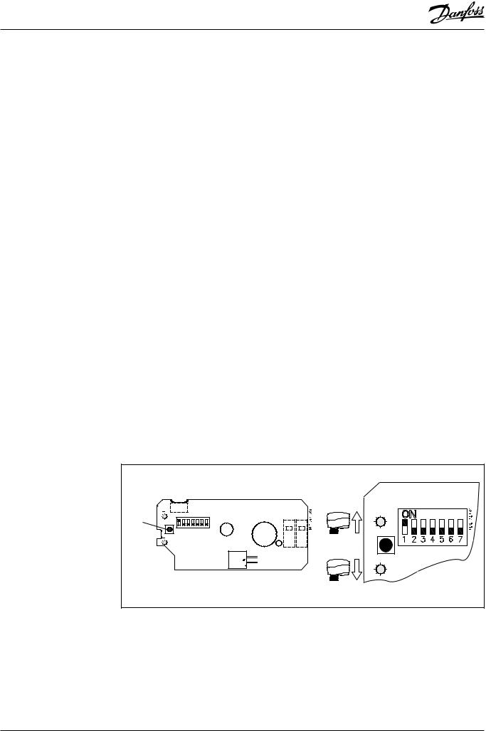
DIP Switch Setting
(for service purposes only)
The actuator has a function selection DIP switch |
• |
SW5: |
|
under the removable cover. |
|
LIN/MOD - Linear or modified flow through |
|
|
|
|
the VZL valves |
The switch provides the following functions: |
|
If set to ON position, the flow through the |
|
• |
SW1: |
|
LINEAR characterized VZL valve will modify |
|
0/2 - Input signal range selector |
|
to equal percentage-wise equals the control |
|
If set to OFF position, the input signal is in the |
|
signal. |
|
range from 2-10 V (voltage input) or |
|
|
|
from 4-20 mA (current input). |
|
If set to OFF position, the flow through the |
|
|
|
valve VZ or VZL remains same as is valve |
|
If set to ON position, the input signal is in the |
|
characteristic in accordance to the control |
|
range from 0-10 V (voltage input) or from |
|
signal. |
|
0-20 mA (current input). |
• |
SW6: |
|
|
||
• |
SW2: |
|
---/ASTK - Anti-blocking function is not |
|
D/I - Direct or inverse acting selector |
|
needed to be activated when operation |
|
If set to OFF position, the actuator is direct |
|
with Danfoss VZ or VZL. To be activated |
|
acting (stem lowers as voltage increases). |
|
when actuator is used by (competitors) |
|
|
|
valves which have possibility to be |
|
If the actuator is set to ON position, the |
|
blocked. |
|
actuator is inverse acting (stem raises as |
|
Exercises the valve to avoid blocking in |
|
voltage increases). |
|
periods when the heating/cooling is off. |
• |
SW3: |
|
If set to ON position (ASTK), the valve motion |
|
---/Seq - Normal or sequential mode selector |
|
is switched on. The actuator opens and closes |
|
If set to OFF position, the actuator is working |
|
the valve every 7 days. |
|
in range 0(2)-10 V or 0(4)-20 mA. |
|
If set to OFF position (---), the function is |
|
|
|
|
|
If set to ON position, the actuator is working in |
|
disabled. |
|
sequential range; 0(2)-5(6) V or (0(4)-10(12)mA) |
• |
SW7: |
|
or (5(6)-10 V) or (10(12)-20 mA). |
||
|
|
|
U/I - Input signal type selector |
• |
SW4: |
|
If set to OFF position, voltage input is |
|
0-5/5-10 V - Input signal range in sequential |
|
selected. |
|
mode |
|
If set to ON position, current input is selected. |
|
If set to OFF position, the actuator is working |
|
|
|
insequentialrange0(2)-5(6)Vor0(4)-10(12)mA. |
• |
Reset button |
|
|
||
|
If set to ON position, the actuator is working in |
|
Press the reset button will cause the |
|
sequential range; 5(6)-10 V or 10(12)-20 mA. |
|
actuator to go through a self stroking cycle |
|
|
|
(press it for 2 s). |
| <![if ! IE]> <![endif]>0-10 V |
<![if ! IE]> <![endif]>INV SEQ |
<![if ! IE]> <![endif]>5-10 V |
<![if ! IE]> <![endif]>MOD ASTX I |
Reset |
|
|
|
|
|
|
|
| <![if ! IE]> <![endif]>2-10 V |
<![if ! IE]> <![endif]>DIR --- |
<![if ! IE]> <![endif]>0-5 V |
<![if ! IE]> <![endif]>LIN --- U |
DEN-SMT/SI |
VD.IR.A1.02 © Danfoss 07/2013 |
3 |
 Loading...