


 BM 2610004573 03-12_BM 2610004573 03-12 6/26/12 7:16 AM Page 1
IMPORTANT: |
IMPORTANT : |
IMPORTANTE: |
Read Before Using |
Lire avant usage |
Leer antes de usar |
|
|
|
Operating/Safety Instructions 
 Consignes de fonctionnement/sécurité
Instrucciones de funcionamiento y seguridad
MRC23EVS
MRF23EVS
MRP23EVS
|
|
|
|
|
|
|
Call Toll Free for |
Pour obtenir des informations |
Llame gratis para |
||
Consumer Information |
et les adresses de nos centres |
obtener información |
|||
|
& Service Locations |
de service après-vente, |
para el consumidor y |
||
|
|
|
appelez ce numéro gratuit |
ubicaciones de servicio |
|
|
|
|
|
||
|
1-877-BOSCH99 (1-877-267-2499) www.boschtools.com |
|
|||
|
|
|
|
|
|
For English Version |
Version française |
Versión en español |
|||
|
See page 2 |
Voir page 28 |
Ver la página 55 |
||
|
|
|
|
|
|

 BM 2610004573 03-12_BM 2610004573 03-12 6/26/12 7:16 AM Page 2
|
General Power Tool Safety Warnings |
|
Read all safety warnings and all instructions. Failure to follow the warnings |
! WARNING |
|
|
and instructions may result in electric shock, fire and/or serious injury. |
|
SAVE ALL WARNINGS AND INSTRUCTIONS FOR FUTURE REFERENCE
The term “power tool” in the warnings refers to your mains-operated (corded) power tool or battery-operated (cordless) power tool.
Work area safety
Keep work area clean and well lit. Cluttered or dark areas invite accidents.
Do not operate power tools in explosive atmospheres, such as in the presence of flammable liquids, gases or dust. Power tools create sparks which may ignite the dust or fumes.
Keep children and bystanders away while operating a power tool. Distractions can cause you to lose control.
Electrical safety
Power tool plugs must match the outlet. Never modify the plug in any way. Do not use any adapter plugs with earthed (grounded) power tools. Unmodified plugs and matching outlets will reduce risk of electric shock.
Avoid body contact with earthed or grounded surfaces such as pipes, radiators, ranges and refrigerators. There is an increased risk of electric shock if your body is earthed or grounded.
Do not expose power tools to rain or wet conditions. Water entering a power tool will increase the risk of electric shock.
Do not abuse the cord. Never use the cord for carrying, pulling or unplugging the power tool. Keep cord away from heat, oil, sharp edges or moving parts. Damaged or entangled cords increase the risk of electric shock.
When operating a power tool outdoors, use an extension cord suitable for outdoor use. Use of a cord suitable for outdoor use reduces the risk of electric shock.
If operating a power tool in a damp location is unavoidable, use a Ground Fault Circuit Interrupter (GFCI) protected supply. Use of an GFCI reduces the risk of electric shock.
Personal safety
Stay alert, watch what you are doing and use common sense when operating a
power tool. Do not use a power tool while you are tired or under the influence of drugs, alcohol or medication. A moment of inattention while operating power tools may result in serious personal injury.
Use personal protective equipment. Always wear eye protection. Protective equipment such as dust mask, non-skid safety shoes, hard hat, or hearing protection used for appropriate conditions will reduce personal injuries.
Prevent unintentional starting. Ensure the switch is in the off-position before connecting to power source and / or battery pack, picking up or carrying the tool.
Carrying power tools with your finger on the switch or energizing power tools that have the switch on invites accidents.
Remove any adjusting key or wrench before turning the power tool on. A wrench or a key left attached to a rotating part of the power tool may result in personal injury.
Do not overreach. Keep proper footing and balance at all times. This enables better control of the power tool in unexpected situations.
Dress properly. Do not wear loose clothing or jewelry. Keep your hair, clothing and gloves away from moving parts. Loose clothes, jewelry or long hair can be caught in moving parts.
If devices are provided for the connection of dust extraction and collection facilities, ensure these are connected and properly used. Use of dust collection can reduce dustrelated hazards.
Power tool use and care
Do not force the power tool. Use the correct power tool for your application. The correct power tool will do the job better and safer at the rate for which it was designed.
Do not use the power tool if the switch does not turn it on and off. Any power tool that cannot be controlled with the switch is dangerous and must be repaired.
-2-

 BM 2610004573 03-12_BM 2610004573 03-12 6/26/12 7:16 AM Page 3
Disconnect the plug from the power source and/or the battery pack from the power tool before making any adjustments, changing accessories, or storing power tools. Such preventive safety measures reduce the risk of starting the power tool accidentally.
Store idle power tools out of the reach of children and do not allow persons unfamiliar with the power tool or these instructions to operate the power tool. Power tools are dangerous in the hands of untrained users.
Maintain power tools. Check for misalignment or binding of moving parts, breakage of parts and any other condition that may affect the power tool’s operation. If damaged, have the power tool repaired before use.
Many accidents are caused by poorly maintained power tools.
Keep cutting tools sharp and clean. Properly maintained cutting tools with sharp cutting edges are less likely to bind and are easier to control.
Use the power tool, accessories and tool bits etc. in accordance with these instructions, taking into account the working conditions and the work to be performed. Use of the power tool for operations different from those intended could result in a hazardous situation.
Service
Have your power tool serviced by a qualified repair person using only identical replacement parts. This will ensure that the safety of the power tool is maintained.
Additional Safety Warnings
GFCI and personal protection devices like electrician’s rubber gloves and footwear will further enhance your personal safety.
Do not use AC only rated tools with a DC power supply. While the tool may appear to work, the electrical components of the AC rated tool are likely to fail and create a hazard to the operator.
Keep handles dry, clean and free from oil and grease. Slippery hands cannot safely control the power tool.
Develop a periodic maintenance schedule for your tool. When cleaning a tool be careful not to disassemble any portion of the tool since internal wires may be misplaced or pinched or safety guard return springs may be improperly mounted.
Certain cleaning agents such as gasoline, carbon tetrachloride, ammonia, etc. may damage plastic parts.
Risk of injury to user. The power cord must only be serviced by a Bosch Factory Service Center or Authorized Bosch Service Station.
Some dust created by power sanding, sawing, grinding, drilling, and other construction activities
contains chemicals known to cause cancer, birth defects or other reproductive harm. Some examples of these chemicals are:
•Lead from lead-based paints,
•Crystalline silica from bricks and cement and other masonry products, and
•Arsenic and chromium from chemicallytreated lumber.
Your risk from these exposures varies, depending on how often you do this type of work. To reduce your exposure to these chemicals: work in a well ventilated area, and work with approved safety equipment, such as those dust masks that are specially designed to filter out microscopic particles.
-3-

 BM 2610004573 03-12_BM 2610004573 03-12 6/26/12 7:16 AM Page 4
Safety Rules for Routers
Hold power tool by insulated gripping surfaces, because the cutter may contact its own cord. Cutting a ”live” wire may make exposed metal parts of the power tool ”live” and shock the operator.
Use clamps or another practical way to secure and support the workpiece to a stable platform. Holding the work by your hand or against the body leaves it unstable and may lead to loss of control.
Always make sure the work surface is free from nails and other foreign objects. Cutting into a nail can cause the bit and the tool to jump and damage the bit.
Never hold the workpiece in one hand and the tool in the other hand when in use. Never place hands near or below cutting surface. Clamping the material and guiding the tool with both hands is safer.
Never lay workpiece on top of hard surfaces, like concrete, stone, etc...
Protruding cutting bit may cause tool to jump.
Always wear safety goggles and dust mask. Use only in well ventilated area.
Using personal safety devices and working in safe environment reduces risk of injury.
After changing the bits or making any adjustments, make sure the collet nut and any other adjustment devices are securely tightened. Loose adjustment device can unexpectedly shift, causing loss of control, loose rotating components will be violently thrown.
Never start the tool when the bit is engaged in the material. The bit cutting edge may grab the material causing loss of control of the cutter.
Always hold the tool with two hands during start-up. The reaction torque of the motor can cause the tool to twist.
When routing or cutting, the direction of feed with the bit’s cutting edge into the material is very important. Always feed the bit into the material in the same direction as the cutting edge is exiting from the material (which is the same direction as the chips are thrown). NOTE: inside and outside cuts will require different feed direction, refer to section on feeding the router. Feeding the tool in the wrong direction causes the cutting edge of the bit to climb out of the work and pull the tool in the direction of this feed.
Never use dull or damaged bits. Sharp bits must be handled with care. Damaged bits can snap during use. Dull bits require more force to push the tool, possibly causing the bit to break.
Never touch the bit during or immediately after the use. After use the bit is too hot to be touched by bare hands.
Never lay the tool down until the motor has come to a complete standstill. The spinning bit can grab the surface and pull the tool out of your control.
Never use bits that have a cutting diameter greater than the opening in the base.
Safety Rules for Router Table
Read and understand the tool manual and these instructions for the use of this table with your tool. Failure to follow all instructions listed below may result in serious personal injury.
Fully assemble and tighten all the fasteners required for this table and mounting the tool.
Do not use the router table until all assembly and installation steps have been completed. Also remember to occasionally check the stand and tool to make sure it is still tight. A loose stand is unstable and may shift in use and cause serious injury.
Make certain the tool is not plugged into a power outlet when installing into the table, making adjustments or changing bits.
Accidental start-up of the tool can cause injury.
Do not plug router motor power cord into standard wall outlet instead it must be plugged into the router table switch. Power tool switches and controls need to be within your reach in emergency situations.
Before operating make sure the entire unit is placed on a solid, flat, level surface. Serious injury could occur if table with the tool is unstable and tips.
-4-

BM 2610004573 03-12_BM 2610004573 03-12 6/26/12 7:16 AM Page 5
Be certain router motor is fully and securely clamped in the router base, periodically check the base fastener or clamping tightness. Adjustment devices must be securely tightened. Tighten as necessary as the tool can loosen from the base due to vibration and may drop or fall unexpectedly when positioned upside down in a table.
Do not use the router table without the overhead guard or auxiliary bit guard. The guards will aid in keeping your hands away from the bit in case of unintended contact with bit.
Never place your fingers under the guard or near the spinning bit. Never hold the workpiece on the out-feed side of bit.
Pressing the workpiece against the out-feed side of the fence may cause material binding and possible kickback pulling your hand back into the bit.
Router bits are intended for wood, woodlike products and plastic e.g. Corian or laminates. Not for cutting or shaping metals. Be sure the workpiece does not contain nails, etc. before routing. Cutting a nail or the like will cause the carbides to be dislodged, fly toward the operator side, and possibly strike you or bystanders.
Match the appropriate bit and its speed to your application. Do not use bits that have a cutting diameter that exceeds the capacity of the tool. Overloading the tool can lead to personal injury or tool failure.
Position and securely clamp the router bit in the collet chuck before making any cuts. If the bit becomes loose during operation it may fly up and away from table possibly striking you or bystanders.
Never use dull or damaged bits. Sharp bits must be handled with care. Damaged bits can snap during use. Dull bits require more force to push the workpiece, possibly causing the bit to break or the material to kickback.
We do not recommend cutting material that is warped, wobbly or otherwise unstable. If the material is slightly curved but otherwise stable cut the material with the concave side against the table or fence. Cutting the material with the concave side up or away from table may cause the warped or wobbly material to roll; causing you to lose control, kickback and serious personal injury may result.
Never start the tool when the bit is engaged in the material. The bit cutting edge may grab the material causing loss of control of the workpiece.
Feed the workpiece against the rotation of the bit. The bit rotates counter-clockwise as viewed from the top of table. Feeding the work in the wrong direction will cause the workpiece to “climb” up on the bit pulling the workpiece and possibly your hands into the rotating bit.
Use push sticks, vertical and horizontally mounted feather boards (spring sticks) and other jigs to hold down the workpiece and keep your hands away from the spinning bit.
Router cuts are blind cuts but the bit still protrudes through the table and you must be aware of the position of your hands relative to the spinning bit.
Use of auxiliary in-feed and out-feed supports is strongly suggested for long or wide workpieces. Long workpieces can flip off the table or cause the table to tip over if not fully supported.
Use the adjustable fence in straight cutting applications. When routing along an entire edge of the workpiece the fence will help maintain stability.
Do not place material between router bit and the fence while routing the edge. This placement may cause the material to become wedged making kickback possible.
Piloted bits along with the starter pin are used when routing internal and external contours on the workpiece. Use the auxiliary bit guard when shaping material with the starter pin and piloted bits. The starter pin and bearing of the piloted bit assist in maintaining control of the workpiece.
Do not place material between piloted router bit and starter pin while shaping contours.
This placement will cause the material to become wedged making kickback possible.
Never touch the bit during or immediately after the use. Contact with a spinning bit will cause injury and after use the bit is too hot to be touched by bare hands.
Do not use the table as workbench or worksurface. The table is not intended to be used as a workbench or work surface other than for routing material. Using it for purposes other than routing may cause damage and make it unsafe to use in routing.
Never stand on the table or use as ladder or scaffolding. Serious injury could occur if the table is tipped or the cutting tool is accidentally contacted. Do not store materials on or near the table such that it is necessary to stand on the table or its stand to reach them.
-5-
 BM 2610004573 03-12_BM 2610004573 03-12 6/26/12 7:16 AM Page 6
Symbols
IMPORTANT: Some of the following symbols may be used on your tool. Please study them and learn their meaning. Proper interpretation of these symbols will allow you to operate the tool better and safer.
Symbol |
|
Name |
|
Designation/Explanation |
|||||||
|
|
||||||||||
|
|
|
|
|
|
|
|
|
|
|
|
|
|
|
|
V |
|
Volts |
|
Voltage (potential) |
|||
|
|
|
|
|
|
|
|
|
|
|
|
|
|
|
|
A |
|
Amperes |
|
Current |
|||
|
|
|
|
|
|
|
|
|
|
|
|
|
|
Hz |
|
Hertz |
|
Frequency (cycles per second) |
|||||
|
|
|
|
|
|
|
|
|
|
|
|
|
|
|
W |
|
Watt |
|
Power |
||||
|
|
|
|
|
|
|
|
|
|
|
|
|
|
|
kg |
|
Kilograms |
|
Weight |
||||
|
|
|
|
|
|
|
|
|
|
|
|
|
min |
|
Minutes |
|
Time |
||||||
|
|
|
|
|
|
|
|
|
|
|
|
|
|
|
|
s |
|
Seconds |
|
Time |
|||
|
|
|
|
|
|
|
|
|
|
|
|
|
|
|
|
|
|
|
|
|
Diameter |
|
Size of drill bits, grinding wheels, etc. |
|
|
|
|
|
|
|
|
|
|
|
|
|
|
|
n0 |
|
No load speed |
|
Rotational speed, at no load |
||||
|
|
|
|
n |
|
Rated speed |
|
Maximum attainable speed |
|||
|
|
|
|
|
|
|
|
|
|
|
|
.../min |
|
Revolutions or reciprocation |
|
Revolutions, strokes, surface speed, |
|||||||
|
|
|
|
|
|
|
|
|
per minute |
|
orbits etc. per minute |
|
|
|
|
|
|
|
|
|
|
|
|
0 |
|
|
|
Off position |
|
Zero speed, zero torque... |
|||||
|
|
|
|
|
|
|
|
|
|
|
|
1, 2, 3, ... |
|
Selector settings |
|
Speed, torque or position settings. |
|||||||
I, II, III, |
|
|
|
Higher number means greater speed |
|||||||
|
|
|
|
|
|
|
|
|
|
|
|
0 |
|
|
|
|
|
|
Infinitely variable selector with off |
|
Speed is increasing from 0 setting |
||
|
|
|
|
|
|
|
|
|
|
|
|
|
|
|
|
|
|
|
|
|
Arrow |
|
Action in the direction of arrow |
|
|
|
|
|
|
|
|
|
|||
|
|
|
|
|
|
|
|
|
|
|
|
|
|
|
|
|
|
|
|
|
Alternating current |
|
Type or a characteristic of current |
|
|
|
|
|
|
|
|
|
|
|
|
|
|
|
|
|
|
|
|
|
Direct current |
|
Type or a characteristic of current |
|
|
|
|
|
|
|
|
|
|||
|
|
|
|
|
|
|
|
|
|
|
|
|
|
|
|
|
|
|
|
|
Alternating or direct current |
|
Type or a characteristic of current |
|
|
|
|
|
|
|
|
|
|||
|
|
|
|
|
|
|
|
|
|
|
|
|
|
|
|
|
|
|
|
|
Class II construction |
|
Designates Double Insulated |
|
|
|
|
|
|
|
|
|
|||
|
|
|
|
|
|
|
|
|
|
|
Construction tools. |
|
|
|
|
|
|
|
|
|
|
|
|
|
|
|
|
|
|
|
|
|
|
|
|
|
|
|
|
|
|
|
|
|
Earthing terminal |
|
Grounding terminal |
|
|
|
|
|
|
|
|
|
|||
|
|
|
|
|
|
|
|
|
|
|
|
|
|
|
|
|
|
|
|
|
Warning symbol |
|
Alerts user to warning messages |
|
|
|
|
|
|
|
|
|
|
|
|
|
|
|
|
|
|
|
|
|
|
|
|
|
|
|
|
|
|
|
|
|
Li-ion RBRC seal |
|
Designates Li-ion battery recycling |
|
|
|
|
|
|
|
|
|
|
|
program |
|
|
|
|
|
|
|
|
|
|
|
|
|
|
|
|
|
|
|
|
|
Ni-Cad RBRC seal |
|
Designates Ni-Cad battery recycling |
|
|
|
|
|
|
|
|
|
|
|
program |
|
|
|
|
|
|
|
|
|
|
|
|
|
|
|
|
|
|
|
|
|
Read manual symbol |
|
Alerts user to read manual |
|
|
|
|
|
|
|
|
|
|
|
|
|
|
|
|
|
|
|
|
|
Wear eye protection symbol |
|
Alerts user to wear eye protection |
|
|
|
|
|
|
|
|
|
|
|
|
-6-
 BM 2610004573 03-12_BM 2610004573 03-12 6/26/12 7:16 AM Page 7
Symbols (continued)
IMPORTANT: Some of the following symbols may be used on your tool. Please study them and learn their meaning. Proper interpretation of these symbols will allow you to operate the tool better and safer.
This symbol designates that this tool is listed by Underwriters Laboratories.
This symbol designates that this tool is recognized by Underwriters Laboratories.
This symbol designates that this tool is listed by Underwriters Laboratories, to United States and Canadian Standards.
This symbol designates that this tool is listed by the Canadian Standards
Association.
This symbol designates that this tool is listed by the Canadian Standards
Association, to United States and Canadian Standards.
This symbol designates that this tool is listed by the Intertek Testing
Services, to United States and Canadian Standards.


 This symbol designates that this tool complies to NOM Mexican Standards.
-7-
 BM 2610004573 03-12_BM 2610004573 03-12 6/26/12 7:16 AM Page 8
Functional Description and Specifications
Disconnect the plug from the power source before making any assembly, adjustments or changing accessories. Such preventive safety
measures reduce the risk of starting the tool accidentally.
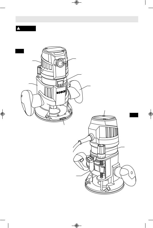
MRF23EVS Fixed Base Router
FIG. 1
Air Vents |
Speed Control Dial |
|
|
|
Motor-To-Base 5V Control |
|
Connection Track |
MRF01 |
|
Fixed Base |
Handles |
MR23EVS Motor
FIG. 2
Sub-Base 
Bit Rotation Arrow
Cord Swivel 

MicroFine
Depth
Adjustment
Control
Trigger Switch
"Lock-On" Button 
Trigger Switch 
Base Clamp Lever
NOTE: For tool specifications refer to the nameplate on your tool.
-8-

 BM 2610004573 03-12_BM 2610004573 03-12 6/26/12 7:16 AM Page 9
Functional Description and Specifications
Disconnect the plug from the power source before making any assembly, adjustments or changing accessories. Such preventive safety
measures reduce the risk of starting the tool accidentally.
|
MRP23EVS Plunge Router |
|
FIG. 3 |
MR23EVS Motor |
|
Afterlock |
Speed Control Dial |
|
Microfine |
||
|
||
Depth |
|
|
Adjustment |
Motor-to-Base 5v Control |
|
Control |
||
Connection Track |
||
|
||
|
Handles |
Plunge
Posts
Depth Rod |
Air Vents |
|
FIG. 4 |
||
|
||
Depth Stop |
Cord |
|
Swivel |
||
Turret |
||
|
||
Bit Rotation Arrow |
Plunge |
|
|
Lock |
|
Trigger Switch |
Lever |
|
|
||
"Lock-On" Button |
|
Trigger Switch 
Base Clamp Lever
MRP01
Plunge Base
Sub-Base 
NOTE: For tool specifications refer to the nameplate on your tool.
-9-

 BM 2610004573 03-12_BM 2610004573 03-12 6/26/12 7:16 AM Page 10
Assembly & Adjustments
INSTALLING A ROUTER BIT
A wide assortment of router bits with different profiles is available separately. Use 1/2" shank whenever possible, and only use good quality bits.
To prevent personal injury, ! WARNING always remove the plug
from power source before removing or installing bits or accessories.
Place router upside down or lay router on its side with the base resting on the bench. Another option is to remove the motor from the base before installing the bit.
NOTE: The bit shank and collet chuck should be clean and free of dust, wood, residue and grease before assembling.
1.Hold the armature shaft in place with the shaft wrench (Fig. 5).
2.Next, use the collet wrench to loosen the collet chuck assembly in counter-clockwise direction (viewed from under the router).
3.Insert the shank of the router bit into the collet chuck assembly as far as it will go, then back the shank out until the cutters are approximately 1/8" to 1/4" away from the collet nut face. To ensure proper gripping of the router bit and minimize run-out, the shank of the router bit must be inserted at least 5/8" (16 mm).
4.With the router bit inserted and the shaft wrench holding the armature shaft, use the collet wrench to firmly tighten the collet chuck assembly in a clockwise direction (viewed from under the router).
Cutter diameter must be at ! WARNING least 1/4” (6.35 mm) smaller
than opening in subbase and/or base for the bit and cutter.
Collet
Wrench Shaft
Wrench
FIG. 5
|
When |
using a templet |
! WARNING |
||
|
guide, |
do not use a router |
|
bit with cutter that exceeds the maximum recommended size (See page 22).
|
|
|
|
To prevent damage to tool, |
|
! |
CAUTION |
||||
|
|
|
|
do not tighten collet |
|
without a bit. |
|||||
|
|
||||
|
|
|
Always be sure the collet |
||
|
! |
WARNING |
|
||
|
|
|
|
chuck is tightened securely |
|
|
|
|
|
||
before use.
REMOVING A ROUTER BIT
1.Use the shaft and collet chuck wrenches as described earlier, and turn the collet chuck assembly in a counter-clockwise direction.
2.Once the collet chuck assembly is loosened continue to turn the collet chuck assembly until it pulls the collet free from its taper, and the router bit can be removed.
NOTE: The collet chuck is self-extracting; it is NOT necessary to strike the collet chuck to free the router bit.
-10-
 BM 2610004573 03-12_BM 2610004573 03-12 6/26/12 7:16 AM Page 11
|
MRF01 Fixed Base Preparation |
FIG. 6 |
Release Base |
|
Clamp Lever Motor Release |
|
Button |
Press Macro |
|
Depth |
|
Adjustment |
|
Lever |
|
B 


 A
A
SLIDE MOTOR
IN BASE
Fine Adjustment
Knob
INSTALLING MOTOR IN FIXED BASE
1.Release the base clamp lever.
2.Line up the MOTOR-TO-BASE 5V CONTROL CONNECTION TRACK with the slot in the fixed base and slide the motor into the carriage.
3.Motor will first slide past the base’s motor release button catch.
4.While holding down the macro depth adjustment lever, push the motor into the base until it reaches the approximate desired depth.
5.Release the macro depth adjustment lever and slide the motor forward or back as needed until the macro adjustment system’s “catch” springs into the macro adjustment detent notch.
6.Set final height position as described in FIXED BASE DEPTH ADJUSTMENT.
7.After making depth adjustments, re-clamp the motor by pressing base clamp lever into closed position.
REMOVING MOTOR FROM FIXED BASE
1.Hold router in horizontal position, open base clamp lever.
2.Press and hold macro depth adjustment lever and gently pull motor outward
3.Press secondary motor-release button and pull motor out of fixed base.
FIXED BASE DEPTH ADJUSTMENT
The MRF01 Fixed Base is equipped with a true micrometer type fine adjustment mechanism, which can be used in any position and provides precise adjustment of the router bit position for unmatched accuracy. When the tool is lowered to the approximate position desired, this device may be adjusted to precisely set the final bit position.
This base also features three horizontal notches on both sides of the motor housing for coarse adjustments. The notches are spaced 1/2" apart which allows you to quickly lower or raise the tool depth in three 1/2" increments. (Approximately 12.7 mm), by simply depressing the coarse adjustment release lever.
TO ADJUST DEPTH
NOTE: All depth adjustments must be made with the base clamp lever released.
1.Open the base clamp lever to release the motor.
2.MACRO DEPTH ADJUSTMENT:
To make a large depth adjustment, depress macro adjustment release lever and raise or lower the motor to the approximate desired depth until it engages in the closet notch. There are three notches in the motor housing which are spaced 1/2" to facilitate this adjustment.
-11-
 BM 2610004573 03-12_BM 2610004573 03-12 6/26/12
3.FINE DEPTH ADJUSTMENT:
To use the fine adjustment feature, turn the fine adjustment knob clockwise to lower the router bit or counter-clockwise to raise it.
4.After making depth adjustments, re-clamp the motor.
NOTES:
•Be sure macro adjustment lever is engaged in one of the macro adjustment notches before making a fine adjustment.
•To prevent damage to tool, avoid wedging the macro adjustment lever against the upper A or lower B portion of the housing as shown in figure 6.
•If the macro adjustment lever is engaged in the notch closest to the collet, the entire depth range can be accessed using fine depth adjustment alone. This makes it unnecessary to use macro depth adjustment, which is particularly helpful when using the router in a router table.
•When the router is installed in a router table, it can be adjusted with a 1/8” hex wrench, not included with all models. (See page 22).
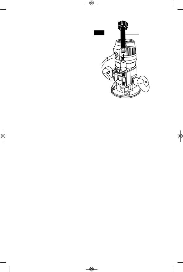
•The RA1002 Fine Adjustment Control Extension, an optional attachment, allows fine adjustment from beyond the top of the motor housing. To install, simply press the RA1002 into the end of the base’s own fine adjustment knob. (Fig. 7)
•To allow precise settings, the indicator ring is graduated in English and Metric increments, and each line is equal to .004” or 1/10 mm.
7:16 AM Page 12
FIG. 7 |
Fine Adjustment |
|
Control Extension |


 Fine Adjustment
Knob
•One full turn of fine adjustment knob = 1/16" or approximately 1.5 mm. The fine adjustment mechanism has a total adjustment range of 1-9/16” (40 mm).
•The indicator ring may be reset to zero without moving the fine adjustment knob, to allow the user to begin the adjustment from any reference point desired.
-12-

 BM 2610004573 03-12_BM 2610004573 03-12 6/26/12 7:16 AM Page 13
MRP01 Plunge Base Preparation
Release Base
Clamp Lever
FIG. 8
INSTALLING MOTOR IN PLUNGE BASE
1.Release the base clamp lever.
2.Line up the MOTOR-TO-BASE 5V CONTROL CONNECTION TRACK with the slot in the plunge motor carriage and slide the motor all the way into the carriage.
3.Motor will first slide past the base’s motor release button catch.
4.Re-clamp the motor by pressing base clamp lever into closed position.
REMOVING MOTOR FROM
PLUNGE BASE
4.Hold router in horizontal position, open base clamp lever, and pull motor upwards until it stops.
5.Press secondary motor-release button and pull motor out of plunge motor carriage.
PLUNGE BASE DEPTH ADJUSTMENT
BASE PLUNGING ACTION
The MRP01 plunge feature simplifies depth adjustments and will allow the cutting bit to easily and accurately enter the workpiece.
To lower the router:
Push plunge lock lever to the left, apply downward pressure until you reach desired
Motor Release
Button
SLIDE MOTOR
IN BASE
Fine
Adjustment
Knob
depth, and release pressure on lever to lock (Fig. 9).
The plunge lock lever is spring loaded and returns automatically to the locked position.
To raise the router:
Push plunge lock lever to the left, release pressure on router and the router will automatically retract the bit from the workpiece.
It is advisable to retract the bit whenever it is not engaged in workpiece.
FIG. 9
Plunge
Lock
Lever
-13-

 BM 2610004573 03-12_BM 2610004573 03-12 6/26/12 7:16 AM Page 14
DEPTH ROD AND TURRET
The depth rod and the depth stop turret are used to control cutting depth as follows;
1.With the bit installed, gently lower the motor until the tip of the router bit just contacts the level surface the router is sitting on. This is the “zero” position, from which further depth adjustments can be accurately made.
2.To set a desired depth of cut, rotate depth stop turret until the lowest step is aligned with the depth rod. Loosen depth indicator knob and lower the depth rod until it contacts the lowest step of the turret. Slide the depth indicator until the red line indicates zero on the depth scale, indicating the point at which the bit just contacts the work (Fig. 10).
3.To set a desired cutting depth, slide the depth rod up until the red depth indicator line attains the desired cutting depth, and secure the rod in position by firmly tightening the depth indicator knob.
4.The desired depth of cut may now be achieved by plunging the router until the depth rod contacts the selected stop on the turret.
ALTERNATE SET-UP FOR
DEPTH ROD AND TURRET
1.An alternative to place a jig of the desired routing depth (such as a hinge which needs to be mortised) on the bottom step of the turret.
2.Next, lower the depth rod until it contacts the jig.
3.Secure the rod in position by firmly tightening the depth indicator knob.
4.Finally, remove the jig.
FIG. 10 Depth Indicator
|
20 |
1/2 |
|
|
10 |
Depth
Indicator
Knob
Depth
Rod
Adjustable
Depth Stops
Depth Stop Turret
DEEP CUTS
For deeper cuts, make several progressively deeper cuts by starting with the highest step on the depth turret, and after each cut, rotate the depth turret to progressively lower steps as desired, until the final depth (lowest step or flat) is reached. Steps progress by 1/8” increments.
The two adjustment screws are provided to allow depth increments of other than 1/8”, which allows you to easily repeat multiple pass operations that have a total depth that is not a multiple of 1/8”
-14-

 BM 2610004573 03-12_BM 2610004573 03-12 6/26/12 7:16 AM Page 15
MRP01 Plunge Base Preparation
AFTERLOCK FINE ADJUSTMENT
The MRP01 is equipped with a true micrometer-type fine adjustment mechanism, which can be used after the plunge lock has been set at any plunge position and provides precise adjustment of the router bit position for unmatched accuracy. When the tool is plunged to the approximate position desired, this device may be adjusted to precisely set the final bit position (Fig. 11).
•To use the fine adjustment, turn the fine adjustment knob clockwise to lower the router bit or counter-clockwise to raise it.
•To allow precise settings, the indicator ring is graduated in Imperial and Metric increments, each line is equal to .004” or 1/10 mm.
•One full turn of fine adjustment knob = 1/16" or approximately 1.5 mm
•The fine adjustment indicator may be reset to zero without moving the fine adjustment knob, to allow the user to begin the adjustment from any reference point desired.
•The fine adjustment mechanism has a total adjustment range of 5/8” (16 mm), which is indicated by the index marker on the back of the housing.
•Whenever the fine adjustment is used, be certain that the index marker is positioned between the two lines to ensure enough travel in the desired direction after the router is plunged into position.
•Note that when the router is plunged to maximum depth or is fully retracted to the top of the posts, the fine adjustment knob cannot move the motor further down or up, as the full extension of travel has been reached.
•Similarly, the fine adjustment knob cannot lower the bit when the depth rod is tightened against the depth turret.
To be certain that your depth settings are as desired, you may want to make test cuts in scrap material before beginning work.
Fine
Adjustment
Knob
Fine
Adjustment 
Indicator
FIG. 11
Index
Marker
-15-

 BM 2610004573 03-12_BM 2610004573 03-12 6/26/12 7:16 AM Page 16
Operating Instructions
PLUGGING THE MOTOR INTO
THE OUTLET / LED LIGHTS
Whenever the motor is plugged in and receiving power, the LEDs at bottom of the motor light up. The LEDs enhance the visibility of the work area when setting the depth and/or starting location, as well as when routing. Note that the motor cannot be turned on when not installed in a Bosch MR-Series router base.
! WARNING The motor should always be unplugged when it is
necessary to reach into the bit area or make adjustments in the bit area, such as when changing bits, templet guides and/or centering the subbase, for examples.
ELECTRONIC VARIABLE
SPEED CONTROL
The electronic speed control feature allows motor speed to be matched to cutter size and material hardness for improved finish, extended bit life, and higher performance. Speed changes are achieved by rotating Control Dial RIGHT to increase speed, LEFT to decrease as indicated on housing (Fig. 1). Speed may be changed while tool is on. The reference numbers on the dial facilitate resetting control to desired speed.
The speed chart indicates the relationship between settings and application, exact settings are determined by operator experience and preference. The bit manufacturer may also have a speed recommendation.
DIAL |
|
|
|
SETTING |
RPM |
APPLICATION |
|
1 |
10,000 |
Hardwoods, |
|
2 |
13,000 |
nonferrous metals, |
|
} larger diameter bits |
|||
3 |
16,000 |
||
|
|
and cutters |
|
4 |
19,000 |
Softwoods, plastics, |
|
counter tops, smaller |
|||
5 |
22,000 |
||
} diameter bits and |
|||
6 |
25,000 |
||
|
|
cutters |
FIG. 12
Routing
Line
Cord
 Swivel
CORD SWIVEL
The power cord features a ball-joint swivel to provide more flexibility in positioning the power cord. It is mounted off of center on the rear of the tool in order to minimize the number of situations where the cord is directly over an intended routing line.
SOFT START FEATURE
Electronic feedback control minimizes torque twist customary in larger routers by limiting the speed at which motor starts.
CONSTANT RESPONSE™ CIRCUITRY
The router's Tachometer-Feedback Constant Response™ Circuitry monitors and adjusts power to maintain the desired RPM for consistent performance and control.
-16-

 BM 2610004573 03-12_BM 2610004573 03-12 6/26/12 7:16 AM Page 17
Operating Instructions
BOSCH-EXCLUSIVE MODULAR ROUTER “TRIGGER CONTROL” ON/OFF SWITCH(ES)
Your Bosch MR23EVS Modular Router System’s bases feature the Bosch-exclusive router “Trigger Control System”, which is unlike any that of any other professional modular router system.
Rather than having to stretch your hand to a toggle switch up high on the router motor, the Bosch Trigger Control System allows you to switch the router on and off in using a trigger switch in the base’s handle --- a familiar switch type and location that is used on almost every other type of power tool. Not only is the trigger switch present on the plunge base, but also in the fixed base, thanks to a sliding motor-to-base electrical contact system
Moreover, the Bosch Trigger Control System’s patented electronic interface between the motor and base is low voltage (only 5V DC, similar to common batteries) and internal, eliminating the need for external motor-to-base cables that could get in the way.
Another advantage of the Bosch router Trigger Control System is its “Smart Base Sensing System” that features the following behaviors:
•Base Required for Operation – The motor cannot be activated unless installed in one of the Bosch MR23EVS series Router Bases
•Motor Won’t Activate During Installation - The motor cannot be accidentally turned on by inserting a base that has the trigger already pulled back, (with or without the lock-button engaged).
•Activation by Router Table Switch – Standard recommended industry practice for use of routers in router tables is that the router’s power cord be plugged into an outlet on a switch assembly of the front of the router and the router be switched on and locked on. The router is then turned on and off using the router table switch. The MR23EVS router series is designed to accommodate this practice.
Lock-On
Button
FIG. 13
Trigger
Switch
!WARNING
•If the MR23EVS motor is already installed in one of its bases and
•If the trigger is engaged (with or without the lock-button engaged),
•And the cord is then plugged into a live outlet, the router turns on.
Never connect the router into a “live” outlet (unless properly installed in a router table) while engaging the trigger (with or without the lock-button engaged), because the router will immediately turn on.
TO TURN THE TOOL “ON”: Simply pull the trigger switch in the right handle.
TO TURN THE TOOL “OFF”: Simply release the trigger switch.
Your router is also equipped with a Lock-ON button located just above the trigger that allows continuous operation without holding the trigger.
TO LOCK THE SWITCH ON: Squeeze trigger fully, depress button and release trigger.
TO UNLOCK THE SWITCH: Squeeze trigger and release it without depressing the Lock-ON button.
If the Lock-ON button is ! WARNING continuously being
depressed, the trigger cannot be released.
-17-

 BM 2610004573 03-12_BM 2610004573 03-12 6/26/12
ENTERING THE WORKPIECE
For best control and results, always allow the router to complete its soft-start ramp up to the speed set (as set using the speed dial) before bringing the bit cutter into contact with workpiece.
Operating in this manner will prolong switch and motor life and will greatly increase the quality of your work.
FEEDING THE ROUTER
As seen from the top of the router, the bit turns clockwise and the cutting edges face accordingly. Therefore, the most efficient cut is made by feeding the router so that the bit turns into the work, not away. Figure 14 shows proper feed for various cuts.
7:16 AM Page 18
•Reduce the feed rate to prevent possible damage to the tool.
•To be certain that your depth and speed settings provide the desired results, test the settings by routing some scrap material before routing the actual workpiece.
•If the router is hard to control, heats up, runs very slowly or leaves an imperfect cut, consider these causes:
1.Wrong direction of feed — hard to control.
2.Feeding too fast — overloads motor.
3.Dull bit — overloads motor.
4.Cut is too large for one pass — overloads motor.
5.Feeding too slow — leaves friction burns on work.
FIG. 14
START
HERE Work
Bit
Direction of Router Feed
FEED RATE
The proper feed rate depends on the hardness of the material and the size of the cut. The best result are achieved when the depth of cut and feed rate allow the motor to operating at the proper speed. Feed the router at a moderate rate. Feed smoothly and steadily (do not force). You will soon learn how the router sounds and feels when it is working best.
ROUTING TIPS
•Always use router bits with the shortest cutting length necessary to produce the desired cut. This will minimize router bit chatter.
•Always be sure the collet chuck is tightened securely before use.
•Soft materials require a faster feed rate than hard materials.
•The router may stall if improperly used or overloaded.
When routing deep cuts, it is best to make multiple progressively deeper cuts rather than trying to rout the full depth in one pass. The appropriate depth of cut will depend on the type of material and the type of cutter being used. The MRP01 Plunge Base and its multiple-step turret is ideally suited for multiplepass routing situations. (See “PLUNGE BASE DEPTH ADJUSTMENT” section.)
EXITING THE WORKPIECE
For best control and results, always move the router so that the bit cutter exits from the workpiece before switching off the router.
Operating in this manner will prolong switch and motor life and will greatly increase the quality of your work.
OVERLOAD PROTECTION
In the unlikely event that the motor becomes overloaded, it will stop automatically. To restart, release the on/off switch, then unplug the cord and plug back into the power source, then start the tool in the normal manner. (When the router is mounted in a router table and connected to the table's switch, and the lock-on button is engaged, restart can be achieved by simply turning the table's switch off and then on again.)
Allow the motor to cool down for 30 seconds by running with no load. If the overload protection stops the tool repeatedly, excessive force is causing the tool to overload.. Don't push so hard and let the tool do the work.
-18-

 BM 2610004573 03-12_BM 2610004573 03-12 6/26/12 7:16 AM Page 19
Guiding the Router
The router can be guided through the work in FIG. 15 |
|
|
any of several ways. The method you use |
FEED |
|
depends, of course, on the demands of the |
||
DIRECTION |
||
particular job and on convenience. |
||
|
Many edge-forming router operations can be done using bits that have bearings.
For routing operations such as grooving or dadoing, it is often necessary to guide the tool in a line parallel to a straight edge. One method of obtaining a straight cut is to securely clamp a board or other straightedge to the work surface, and guide the edge of the router sub-base along this path (Fig. 15).
Board
Guide
Securely Clamp
Board Guide
DELUXE ROUTER GUIDE
The Bosch deluxe router guide is an optional accessory that will guide the router parallel to a straight edge or allow you to create circles and arcs.
The deluxe router guide is supplied with two rods and screws to fasten the guide (Fig. 16). In addition, it features a fine adjustment knob and indicator for accurately positioning the edge guide relative to the bit. With the guide installed and adjusted, the router should be
FIG. 16
6mm Wing Screws
fed normally, keeping the guide in contact with the edge of the workpiece at all times. The deluxe router guide may also be positioned directly under the router base for operations where a cut is needed close to or at the edge of the work.
The deluxe router guide includes a dust extraction hood and the VAC002 vacuum hose adapter.
For complete instructions on installation and operation, please refer to the instructions which are included with this accessory.
FEED
DIRECTION
Base |
|
Fine Adjustment |
|
|
indicator |
Cut |
|
|
|
|
Router |
|
|
Guide |
|
|
Rods |
Desired |
Workpiece |
Fine Adjustment |
Width |
Knob |
-19-

 BM 2610004573 03-12_BM 2610004573 03-12 6/26/12 7:16 AM Page 20
TEMPLET GUIDES
This router can also be used with the optional Bosch-exclusive quick-change templet guide system, which firmly grips the guides with a spring-loaded ring. Unlike conventional threaded templet guides, there is no threaded ring that can come loose while routing.
Templet guides are used with a number of special accessories, such as hinge templets, which are listed in your BOSCH catalog. In addition, special templets are easily prepared for cutting repeated patterns, special designs, inlays, and other applications. A templet pattern may be made of plywood, hardboard, metal or even plastic, and the design can be cut with a router, jigsaw, or other suitable cutting tool. Remember that the pattern will have to be made to
FIG. 17 |
Collet Chuck |
||
|
|||
Router Bit |
Templet |
Router |
|
Guide |
Sub-Base |
||
|
|||
|
|
Templet |
|
|
|
Pattern |
|
Offset |
|
Workpiece |
|
compensate for the distance between the router bit and the templet guide (the “offset”), as the final workpiece will differ in size from the templet pattern by that amount, due to the bit position (Fig. 17).
INSTALLING TEMPLET |
Templet Guide |
Templet |
|
GUIDE ADAPTER |
Release Lever |
||
|
Guide Adapter |
||
(Optional Accessory) |
|
||
FIG. 18 |
(Optional |
||
Place templet guide adapter over the holes in |
Accessory) |
||
|
|||
the center of the sub-base, and align the two |
|
|
|
threaded holes in the bottom of adapter with |
|
|
|
the countersunk holes in sub-base. Fasten |
|
|
|
adapter with the screws provided. Note that |
|
|
|
the adapter is reversible, so the release lever |
|
|
|
may be positioned as desired. (Fig. 18) |
|
|
To insert or change a templet guide:
1. Retract the templet guide release lever.
2. Align the cutaways on the templet guide with the tabs on the bottom of the templet guide adapter.
3. Insert the templet guide.
4. Release the lever to grip the templet guide in place.
Mounting
Screws
Templet Guide
(Optional Accessory)
-20-
 BM 2610004573 03-12_BM 2610004573 03-12 6/26/12 7:16 AM Page 21
CENTERING THE SUB-BASE OR
TEMPLET GUIDES
Your router features the Bosch “Precision Centering Design”. Its sub-base is precisely centered at the factory. This positions the bit at the center of the sub-base and optional templet guides.
Precision centering allows you to use the edge of the subbase or templet guides to closely follow jigs such as straight guides, templets, and dovetail fixtures without worrying about bit walk-off from the intended cut line for any reason, including the orientation of the router’s handles relative to the jig.
To most precisely re-center the sub-base or templet guides, attach the sub-base using the optional Bosch RA1151 Centering Device. Follow steps 1-8 (Fig. 19 & 20).
1.If a templet guide is to be centered, Install the templet guide adapter and template guide (optional attachments) as described elsewhere in this manual.
2.Position the sub-base so that its pan-head screw holes are over the matching set of threaded holes in the base.
3.Insert the pan-head screws through the sub-base and tighten them until they are snug, but still allow the sub-base to move.
4.Prepare the Centering Device:
•Use narrow end of steel shaft when inserting into 1/4” collet, wider end of cone when inserting into 1/2” collet.
•When centering subbase or templet guide that has opening of more than ½”, slide the wide plastic sleeve over the steel shaft.
5.Slide centering sleeve through the sub-base or templet guide and into collet. Tighten collet nut with fingers to put slight grip on centering cone.
6.Lightly press centering sleeve into sub-base or templet guide to center.
7.Tighten the pan-head screws. Remove centering sleeve.
8.The precision centering of the sub-base or templet guide is complete.
Centering Sleeve
(Optional
Accessory)
FIG. 19
FIG. 20 |
Centering |
|
|
|
Sleeve |
Sub-Base
Screw
Centering Shaft
(Optional Accessory)
Sub-Base
Screw
Sub-Base
Centering
Shaft
Templet
Guide
Sub-Base
-21-

 BM 2610004573 03-12_BM 2610004573 03-12 6/26/12 7:16 AM Page 22
MAXIMUM BIT/CUTTER SIZE FOR |
USE WITH THREADED |
TEMPLET GUIDES |
TEMPLET GUIDES |
When using a templet guide, use only router bit with cutters that are 1/16” less than the internal diameter of the templet guide, such as in the table below.
Also available as an optional accessory is an additional adapter, the RA1100, that allows use of conventional threaded templet guides with the Bosch quick-release system.
Bosch |
Bushing |
External |
Internal |
Max |
Templet |
Depth |
Diameter |
Diameter |
Bit/Cutter |
Guide |
A |
B |
B |
Diameter |
|
|
|||
RA1101 |
3/16” |
5/16” |
1/4” |
3/16” |
RA1103 |
9/64” |
5/16” |
17/64” |
13/64” |
RA1105 |
9/64” |
7/16” |
3/8” |
5/16” |
RA1107 |
5/16” |
7/16” |
3/8” |
5/16” |
RA1109 |
7/16” |
1/2” |
13/32” |
11/32” |
RA1111 |
3/16” |
5/8” |
17/32” |
15/32” |
RA1113 |
1/2” |
5/8” |
17/32” |
15/32” |
RA1115 |
3/16” |
3/4” |
21/32” |
19/32” |
RA1117 |
31/64” |
13/16” |
5/8” |
9/16” |
RA1119 |
31/64” |
1” |
25/32” |
21/32” |
RA1121 |
7/16” |
1-3/8” |
1-19/64” |
1-15/64” |
|
|
|
|
|
Use in Router Table
Your router can also be used in a router table. The MR001 fixed base is designed to allow easy depth adjustment in a table.
The MRP01 Plunge Base is ! CAUTION not recommended for use in
a router table. Damage to plunge router base may occur.
To eliminate the hassle of installing your router’s own base on the router table and later having to convert it back for non-table use, Bosch offers additional MRF01 Fixed Bases separately so that one base can be permanently attached to your router table, leaving your other fixed base available for nontable use.
ATTACHING BASE TO
MOUNTING PLATE
Attach the MRF01 to the router table’s mounting plate using the three M4 holes screws provided. The 3-hole pattern on the bottom of the base follows the industrystandard three-hole pattern for professional routers. Depending on the thickness of your router table or router table mounting plate, you may need to purchase longer M4 screws with tapered heads (Fig. 21).
If your router table mounting plate does not have countersunk holes in either of those patterns, you will need to determine the hole locations, drill and countersink them, also locate and drill a hole for the over-table adjustment wrench.
-22-

 BM 2610004573 03-12_BM 2610004573 03-12 6/26/12 7:16 AM Page 23
Use in Router Table
CONNECT THE ROUTER AND THE
ROUTER TABLE SWITCH
To prepare for use of the switch:
1.Make sure the router table’s switch and the router table switch are both turned off.
2.Plug the router table switch cord to wall outlet.
3.Plug the router into the "pigtail" socket on the router table switch.
4.Lock router switch on: squeeze trigger, depress lock-on button, and release trigger.
5.Use the router table switch to start and stop the router.
DEPTH ADJUSTMENT
(See pages 11 & 12)
FEEDING THE WORKPIECE
ON A ROUTER TABLE
Always use your router table's fence or starter pin and the appropriate guard and follow the router table's instruction manual. ALWAYS feed the workpiece from right to left across the front of the bit. On Bosch router tables, the correct feed direction is also shown on fence housing and on the featherboards, when they have been properly installed. (Fig. 22)
Whenever possible, when using the fence, use a push stick to push the workpiece, especially when working with narrow pieces.
For complete instructions on operation of a router in a router table, please refer to the instructions that come with the router table.
FIG. 21 |
Hex |
|
M4 |
||
Wrench |
||
Screw |
||
|
||
Mounting |
|
|
Plate |
|
|
Shown after |
Hole for Hex |
|
Wrench |
||
subbase has |
||
|
||
been removed |
|
Quick-release clamp lever and depth adjustment controls should face the front of the router table
FIG. 22
DIRECTION
OF FEED
Fence Face |
Fence Face |
Workpiece
Bit Bearing
TOP VIEW
NOTE: For clarity, guard and featherboard removed from drawing.
-23-
 BM 2610004573 03-12_BM 2610004573 03-12 6/26/12 7:16 AM Page 24
Router Dust Extraction
! WARNING |
Read and understand these |
|
instructions and tool |
|
manual for use of these accessories.
Do not reach in area of the bit while the router is ON or plugged in as indicated by LEDS being on).
To avoid entangling hoses, ! CAUTION do not use this dust
extraction hood at the same time as any other dust extraction hood.
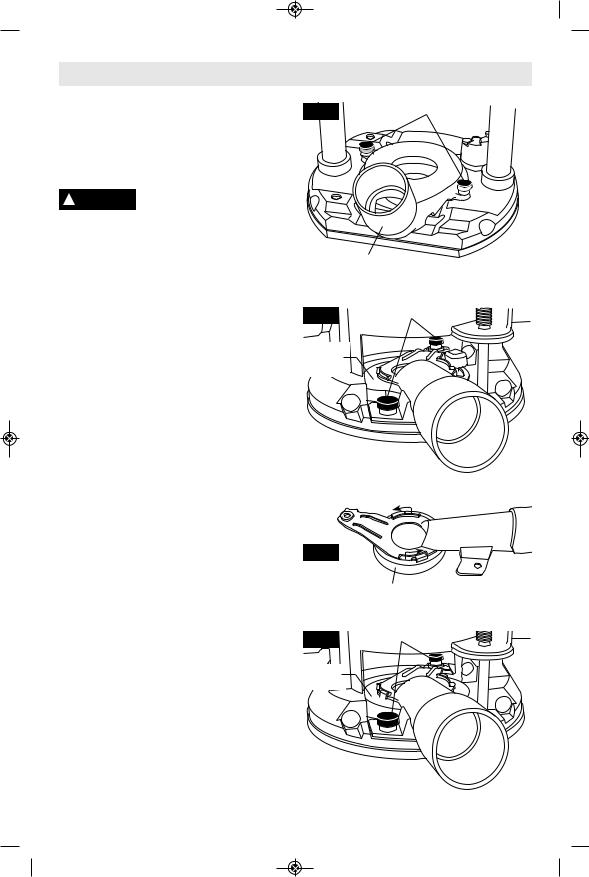
PLUNGE BASE DUST EXTRACTION
This dust extraction hood is designed for use in the plunge base (MRP001) when routing is done in the middle of the workpiece, such as when creating slots or routing patterns for inlays. If you have a shop vacuum system, you can attach the dust extraction hood for improved visibility, accuracy and utility, particularly in freehand routing.
To attach, position as shown and secure adapter to base with the thumbscrews provided (Fig. 23).
The dust extraction hood can also be installed with the hose outlet facing the front of the tool.
FIXED BASE DUST EXTRACTION
This dust extraction hood is designed for use with the MRF001 fixed base. It is installed differently depending on whether or not the optional templet guide adapter is installed.
•If templet guide adapter is installed, position port-and-cover piece as shown and secure to base with the thumbscrews provided (Fig. 24).
•If no templet guide adapter is installed, first attach the side shroud by rotating it onto the bottom of the port-and-cover piece (Fig. 25). Then position the hood assembly as shown and secure to base with the thumbscrews provided (Fig. 26).
•The fixed base dust extraction hood can also be installed with the hose outlet facing the front of the tool.
FIG. 23 |
4mm Thumb Screws |
Dust Extraction Hood
(Optional Accessory)
FIG. 24 |
4mm Thumb Screws |
Templet
Guide
Adapter
Dust Extraction Hood 
(Optional Accessory)
FIG. 25
|
Side Shroud |
FIG. 26 |
4mm Thumb Screws |
Side |
|
Shroud |
|
Dust Extraction Hood 
(Optional Accessory)
-24-
 BM 2610004573 03-12_BM 2610004573 03-12 6/26/12 7:16 AM Page 25
Router Dust Extraction
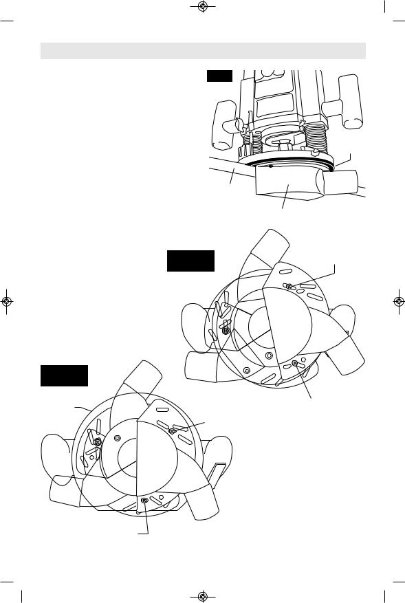
EDGEFORMING DUST
EXTRACTION
This dust extraction hood (optional accessory) is used for dust collection when edge-forming
You can attach the edge-forming hood in several places according to your needs or preferences. This hood is attached using two of the screw holes on the router base that are used to attach the router’s sub-base. Choose the desired location for the hood. Loosen and take out the two screws from the router base and attach the dust extraction hood — over the router’s sub-base — using the screws provided with the hood. Securely tighten the screws.
FIG. 27
Workpiece
Edge
Dust Extraction Hood
Router
Sub-Base
4mm x 16mm
FIG. 29 Screw OTHER BASES
|
Dust |
|
Extraction |
|
Hood |
FIG. 28 |
|
PLUNGE BASE |
|
Router |
4mm x 16mm |
Sub-Base |
Screw |
|
4mm x 16mm |
|
Screw |
Dust
Extraction
Hood
4mm x 16mm Screw
-25-
 Loading...