


GSB 12 VE-2
Bosch GSB 12 VE-2, GSB 14.4 VE-2, GSB 24 VE-2, GSB 18 VE-2, GSR 12 VE-2 Operating Instructions Manual
...
Bedienungsanleitung
Operating Instructions
Instructions d’emploi
Instrucciones de servicio
Manual de instruções
Istruzioni d’uso
Gebruiksaanwijzing
Betjeningsvejledning
Bruksanvisning
Brukerveiledningen
Käyttöohje
Oδηγία χειρισµού
Kullanım kılavuzu
Deutsch
English
Français
Español
Português
Italiano
Nederlands
Dansk
Svenska
Norsk
Suomi
Eλληνικά
Türkçe
GSB/GSR 12 VE-2
GSB/GSR 14,4 VE-2
GSB/GSR 18 VE-2
GSB/GSR 24 VE-2

2 • 2 609 932 156 • 03.04
3 • 2 609 932 156 • 03.04
2,0 Ah (NiCd)
2 607 335 266 (18 V)
2 607 335 446 (24 V)
2,4 Ah (NiCd)
2 607 335 430 (12 V)
2 607 335 432 (14,4 V)
2 607 335 434 (18 V)
2 607 335 448 (24 V)
2,6 Ah (NiMH)
2 607 335 556 (12 V)
2 607 335 558 (14,4 V)
2 607 335 560 (18 V)
2 607 335 562 (24 V)
3,0 Ah (NiMH)
2 607 335 488 (12 V)
2 607 335 490 (14,4 V)
2 607 335 508 (18 V)
2 607 335 510 (24 V)
AL 15 FC 2498
(7,2 V–24 V)
2 607 224 484 (EU)
2 607 224 486 (UK)
2 607 224 488 (AUS)
AL 60 DC 2422
(7,2 V–24 V)
2 607 224 410
(EU/UK/AUS)
GSB 12/14,4 VE-2
GSR 12/14,4 VE-2
2 605 438 535
GSB 18/24 VE-2
GSR 18/24 VE-2
2 605 438 536
2 607 000 205
2 607 000 239*
PH Nr. 2
2 607 000 248*
PZ Nr. 2
2 607 000 258*
T 20
2 607 000 317*
SW 3 mm
2 607 000 221*
0,8 x 5,5 mm
*
3 ×
2 608 572 182
AL 60 DV 1419
(7,2 V–14,4 V)
2 607 224 440 (EU)
2 607 224 442 (UK)
2 607 224 444 (AUS)
2 607 000 204
AL 30 DV 1450
(7,2 V–14,4 V)
2 607 224 702 (EU)
2 607 224 704 (UK)
2 607 224 706 (AUS)
AL 60 DV 2425
(7,2 V–24 V)
2 607 224 426 (EU)
2 607 224 428 (UK)
2 607 224 430 (AUS)
GSB 12–24 VE-2
GSR 18 VE-2
GSR 24 VE-2
2 602 025 134
4 • 2 609 932 156 • 03.04
1
2
3
4
5
6
10
7
8
GSR 12
9
GSB 24
5 • 2 609 932 156 • 03.04
C
13
➊
D
13
➋
A
9
11
B
7
12
12
E
14
F
16
15

Deutsch - 1
Gerätekennwerte
Akku-Bohrschrauber GSR 12 VE-2 14,4 VE-2 18 VE-2 24 VE-2
Bestellnummer 0 601 ... 912 5.. 912 4.. 912 3.. 912 2..
Leerlaufdrehzahl
1. Gang [min
-1
] 0–400 0–400 0–400 0–400
2. Gang [min
-1
] 0–1 400 0–1 400 0–1 300 0–1 300
Drehmomenteinstellbereich [Nm] 2–10 2–10 2–10 2–10
Drehmoment, max.
Weicher Schraubfall [Nm] 26 30 38 44
Harter Schraubfall [Nm] 65 70 80 85
Bohr-Ø Stahl, max. [mm] 13 13 13 16
Bohr-Ø Holz, max. [mm] 32 35 38 40
Schrauben-Ø, max. [mm] 8 10 12 14
Bohrfutterspannbereich [mm] 1,5 – 13 1,5–13 1,5–13 1,5–13
Bohrspindelgewinde 1/2 " 1/2 " 1/2 " 1/2 "
Gewicht ohne Akku, ca. [kg] 1,6 1,6 1,6 1,6
Akku-Schlagbohrschrauber GSB 12 VE-2 14,4 VE-2 18 VE-2 24 VE-2
Bestellnummer 0 601 ... 913 5.. 913 4.. 913 3.. 913 2..
Leerlaufdrehzahl
1. Gang [min
-1
] 0–500 0–500 0–500 0–500
2. Gang [min
-1
] 0–1 700 0–1 750 0–1 800 0–1 800
Schlagzahl [/min] 0–21 000 0–21 000 0–21 000 0–21 000
Drehmomenteinstellbereich [Nm] 1,5 – 9 1,5–9 1,5–9 1,5–9
Drehmoment, max.
Weicher Schraubfall [Nm] 22 24 28 34
Harter Schraubfall [Nm] 60 65 70 75
Bohr-Ø Stahl, max. [mm] 13 13 13 16
Bohr-Ø Holz, max. [mm] 30 32 35 38
Bohr-Ø in Mauerwerk, max. [mm] 10 12 14 16
Schrauben-Ø, max. [mm] 8 8 10 12
Bohrfutterspannbereich [mm] 1,5 – 13 1,5–13 1,5–13 1,5–13
Bohrspindelgewinde 1/2 " 1/2 " 1/2 " 1/2 "
Gewicht ohne Akku, ca. [kg] 1,8 1,8 1,9 1,9
Akku
Temperaturüberwachung NTC NTC NTC NTC
Nennspannung [V=] 12 14,4 18 24
Kapazität NiCd [Ah] 2,4 2,4 2,0 2,0
Gewicht NiCd, ca. [kg] 0,7 0,8 0,9 1,4
Kapazität NiMH [Ah] 2,6 2,6 2,6 2,6
Gewicht NiMH, ca. [kg] 0,7 0,8 1,0 1,3
Bitte die Bestellnummer Ihrer Maschine beachten. Die Handelsbezeichnungen einzelner Maschinen können variieren.
6 • 2 609 932 156 • 03.04

Deutsch - 2
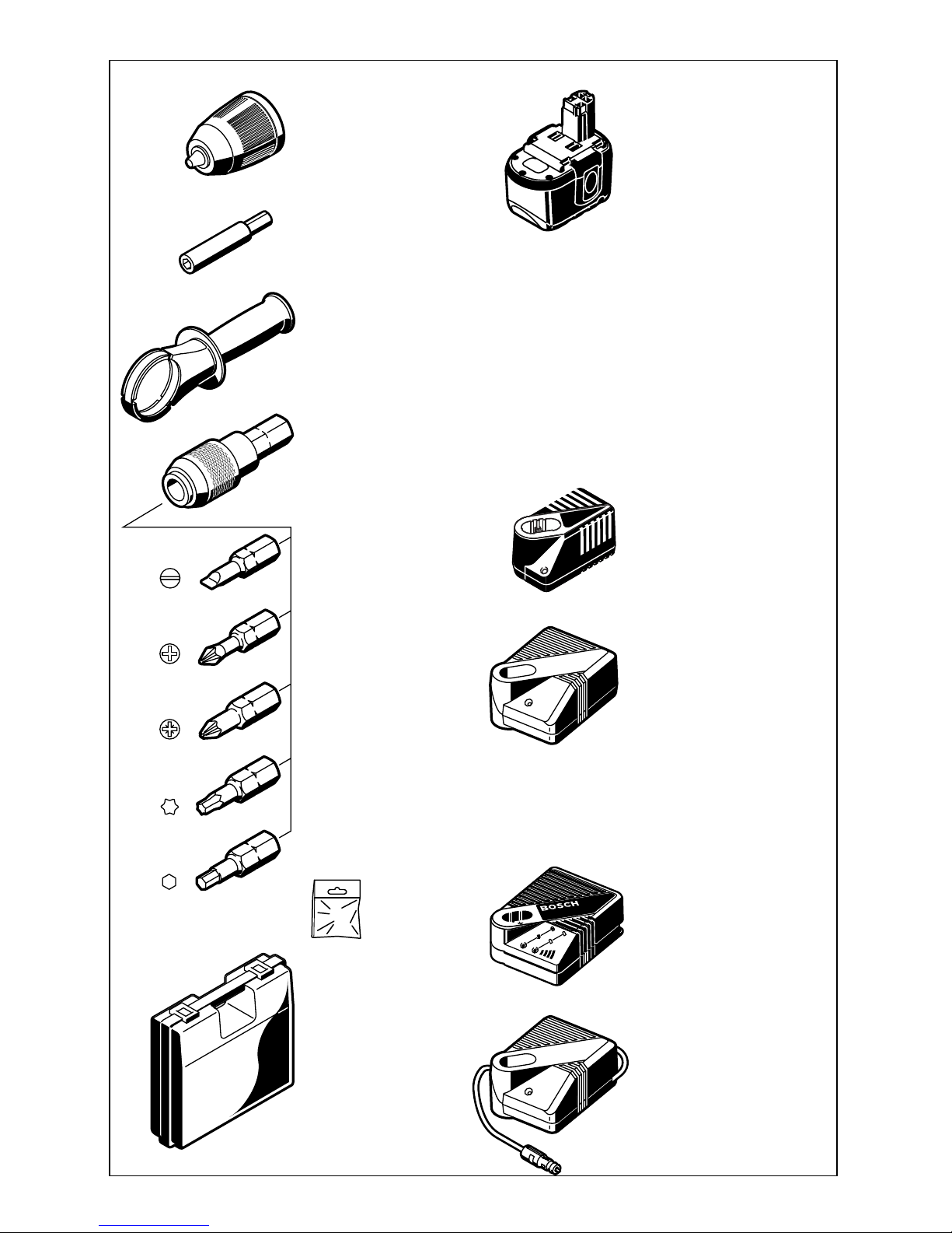
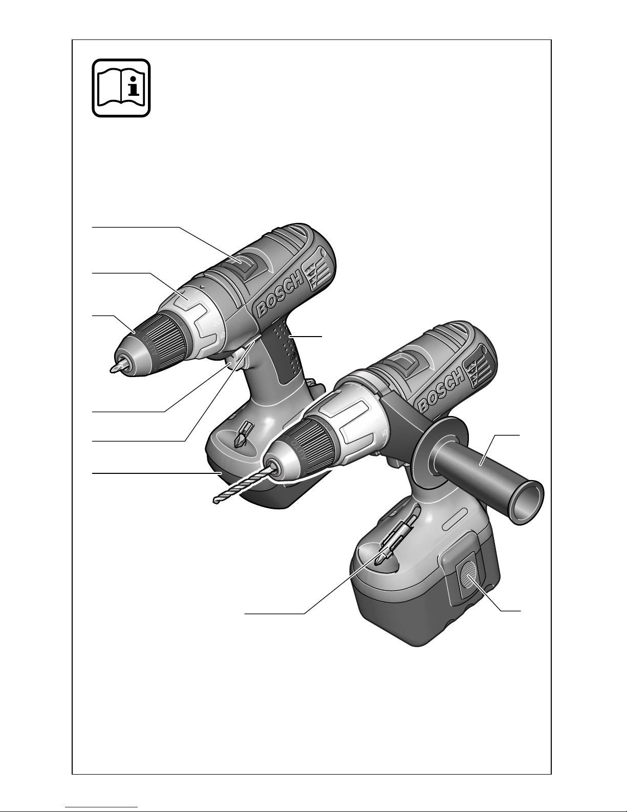
1 Gangwahlschalter
2
Drehmoment-Einstellring
3
Schnellspannbohrfutter
4
Ein-/Ausschalter
5
Drehrichtungsumschalter
6
Akku*
7
Universalbithalter*
8
Akku-Entriegelungstaste
9
Zusatzgriff*
10 Softgrip
11 Spannband*
12 Schraubendrehereinsatz (Bit)*
13 Innensechskantschlüssel*
14 Sicherungsschraube
15 Abdeckkappe
16 Schleifkohlenhalterung
*
Abgebildetes oder beschriebenes Zubehör gehört
teilweise nicht zum Lieferumfang.
GSR: Das Gerät ist bestimmt zum Eindrehen und
Lösen von Schrauben sowie zum Bohren in Holz,
Metall, Keramik und Kunststoff.
GSB: Das Gerät ist bestimmt zum Eindrehen und
Lösen von Schrauben, zum Bohren in Holz, Metall, Keramik und Kunststoff und zum Schlagbohren in Ziegel, Beton und Gestein.
Gefahrloses Arbeiten mit dem
Gerät ist nur möglich, wenn Sie
die Bedienungsanleitung und
die Sicherheitshinweise vollständig lesen und die darin ent-
haltenen Anweisungen strikt befolgen. Zusätzlich müssen die allgemeinen
Sicherheitshinweise im beigefügten Heft befolgt werden.
■
Schutzbrille tragen.
■
Bei langen Haaren Haarschutz tragen. Nur mit
eng anliegender Kleidung arbeiten.
■
Vor jeder Benutzung Gerät und Akku überprüfen. Werden Schäden festgestellt, Gerät nicht
weiter benutzen. Reparatur nur von einem
Fachmann durchführen lassen. Gerät nie
selbst öffnen.
■
Vor allen Arbeiten am Gerät (z. B. Wartung,
Werkzeugwechsel, usw.) sowie bei dessen
Transport und Aufbewahrung den Drehrichtungsumschalter stets in Mittelstellung
bringen.
Sonst besteht Verletzungsgefahr bei
unbeabsichtigtem Betätigen des Ein-/Ausschalters.
■
Überzeugen Sie sich vor der Benutzung vom
sicheren Sitz des Akkus im Gerät.
■
Das Gerät nicht so weit belasten, dass es zum
Stillstand kommt.
■
GSB 18 VE-2 /GSB 24 VE-2 /GSR 18 VE-2 /
GSR 24 VE-2:
Verwenden Sie Ihr Gerät nur
mit dem Zusatzgriff
9
.
Beim Arbeiten das Gerät immer fest mit beiden
Händen halten und für einen sicheren Stand
sorgen.
■
Verwenden Sie geeignete Suchgeräte, um
verborgene Versorgungsleitungen aufzuspüren, oder ziehen Sie die örtliche Versorgungsgesellschaft hinzu.
Kontakt mit Elektroleitungen kann zu Feuer
und elektrischem Schlag führen.
Beschädigung einer Gasleitung kann zur Explosion führen. Eindringen in eine Wasserleitung verursacht Sachbeschädigung.
■
Gerät gut festhalten: Beim Festziehen können
kurzzeitig hohe Reaktionsmomente auftreten.
■
Sichern Sie das Werkstück. Ein mit Spann-
vorrichtungen oder Schraubstock festgehaltenes Werkstück ist sicherer gehalten als mit Ihrer Hand.
■
Niemals Kindern die Benutzung des Gerätes
gestatten.
■
Bosch kann nur dann eine einwandfreie Funktion des Gerätes zusichern, wenn das für dieses Gerät vorgesehene Original-Zubehör verwendet wird.
Akku und Ladegerät
■
Unbedingt die beiliegende Bedienungsanleitung des Ladegerätes lesen!
■
Akku nicht öffnen sowie vor Stoß schützen.
Trocken und frostsicher aufbewahren.
■
Erwärmten Akku vor dem Laden abkühlen lassen.
■
Akku vor Hitze und Feuer schützen: Explosionsgefahr! Akku nicht auf Heizkörper ablegen
oder längere Zeit starker Sonneneinstrahlung
aussetzen, Temperaturen über 50 °C schaden.
■
Den Akku nicht in den Hausmüll, ins Feuer
oder ins Wasser werfen.
Geräteelemente
Bestimmungsgemäßer Gebrauch
Zu Ihrer Sicherheit
7 • 2 609 932 156 • 03.04
Deutsch - 3
Akku laden
Ein neuer oder längere Zeit nicht verwendeter
Akku bringt erst nach ca. 5 Lade- und Entladezyklen seine volle Leistung.
Zur Entnahme des Akkus
6
die Entriegelungstas-
ten
8
drücken und den Akku nach unten heraus-
ziehen. Keine Gewalt anwenden.
Der Akku ist mit einer NTC-Temperaturüberwa-
chung ausgestattet, welche Ladung nur im Temperaturbereich zwischen 0 °C und 45 °C zulässt.
Dadurch wird eine hohe Akku-Lebensdauer erreicht.
Eine wesentlich verkürzte Betriebszeit nach der
Aufladung zeigt an, dass die Akkus verbraucht
sind und ersetzt werden müssen.
■
Hinweise zum Umweltschutz beachten.
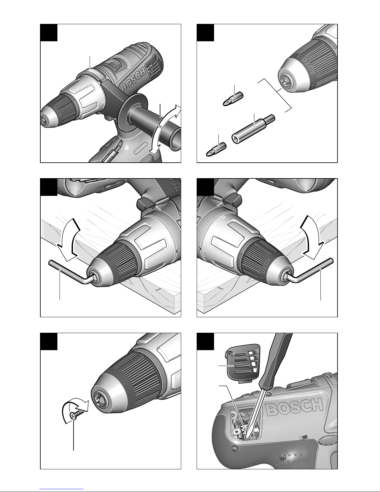
Das Griffstück durch Linksdrehen lösen. Den Zusatzgriff
9
schwenken und der Arbeitsstellung
anpassen. Das Spannband
11 des Zusatzgriffs
muss dabei in der Nut bleiben.
Das Griffstück danach durch Rechtsdrehen
wieder fest anziehen.
Das Bohrfutter öffnen, bis das Werkzeug eingesetzt werden kann. Das Werkzeug einsetzen.
Die Hülse des Schnellspannbohrfutters
3
von
Hand kräftig zudrehen bis kein Überrasten
(„Klick“) mehr hörbar ist. Das Bohrfutter wird dadurch automatisch verriegelt.
Drehen Sie die Hülse in Gegenrichtung um das
Werkzeug zu entnehmen.
Schrauben (siehe Bild )
Das Bit 12 direkt in das Bohrfutter einspannen.
Für den schnellen Wechsel wird der Einsatz des
Universalbithalters 7 empfohlen.
Akku einsetzen
Den Drehrichtungsumschalter 5 auf Mitte = Ein-
schaltsperre stellen und den geladenen Akku 6 in
den Griff einrasten lassen.
Ein-/Ausschalten
Zur Inbetriebnahme des Gerätes den Ein-/Ausschalter 4 drücken und gedrückt halten.
Die Maschine läuft je nach Druck
auf den Ein-/Ausschalter 4 mit variabler Drehzahl zwischen 0 und Maximum. Leichter Druck bewirkt eine
kleine Drehzahl und macht somit
einen sanften, kontrollierten Anlauf
möglich. Das Gerät nicht so stark
belasten, dass es zum Stillstand
kommt.
Zum Ausschalten des Gerätes den Ein-/Aus-
schalter 4 loslassen.
Auslaufbremse
Beim Loslassen des Ein-/Ausschalters 4 wird das
Bohrfutter abgebremst und dadurch das Nachlaufen des Werkzeugs verhindert.
Bei Schraubarbeiten den Ein-/Ausschalter 4 erst
dann loslassen, wenn die Schraube bündig in
das Material eingedreht ist. Der Schraubenkopf
dringt dann nicht in das Material ein.
Mechanische Gangwahl
Mit dem Gangwahlschalter 1 können zwei Drehzahlbereiche vorgewählt werden:
1. Gang: Niedrige Drehzahl, große Kraft.
2. Gang: Hohe Drehzahl, geringere Kraft.
Die Gänge können bei laufender Maschine um-
geschaltet werden; dies sollte aber nicht unter
Last erfolgen. Empfohlen wird jedoch das Umschalten bei Stillstand. Lässt sich der Gangwahlschalter 1 bei stillstehender Maschine nicht in die
Endlage schieben, dann zusätzlich das Bohrfutter etwas drehen bzw. den Ein-/Ausschalter 4
nochmals kurz betätigen.
Vor der Inbetriebnahme
Zusatzgriff (siehe Bild )
(GSB 12 –24 VE-2/
GSR 18 –24 VE-2)
Werkzeugwechsel
A
B
Inbetriebnahme
8 • 2 609 932 156 • 03.04
Deutsch - 4
Vollautomatische Spindelarretierung
(Auto-Lock)
Bei nicht gedrücktem Ein-/Ausschalter 4 wird die
Bohrspindel arretiert.
Dies ermöglicht ein schnelles, bequemes und
einfaches Wechseln des Einsatzwerkzeuges im
Bohrfutter.
Das arretierte Bohrfutter ermöglicht das Nachziehen überstehender Schrauben durch Verwendung der ausgeschalteten Maschine als Schraubendreher.
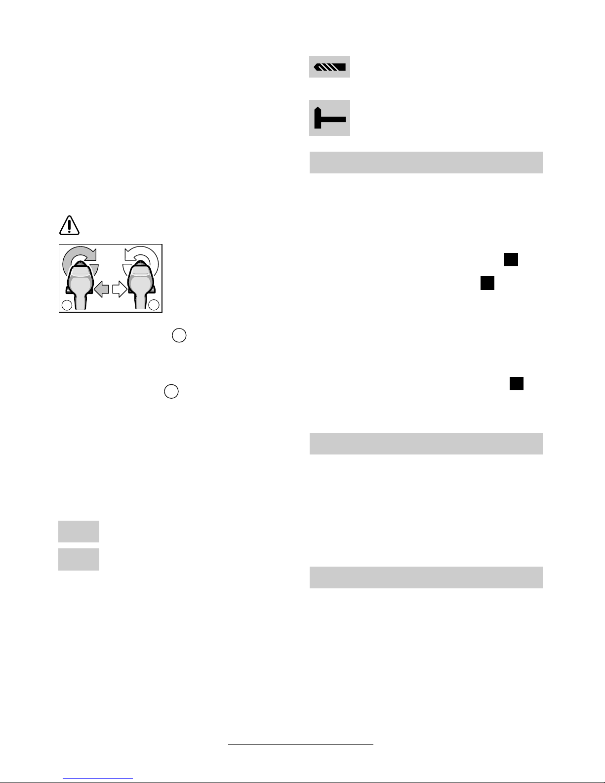
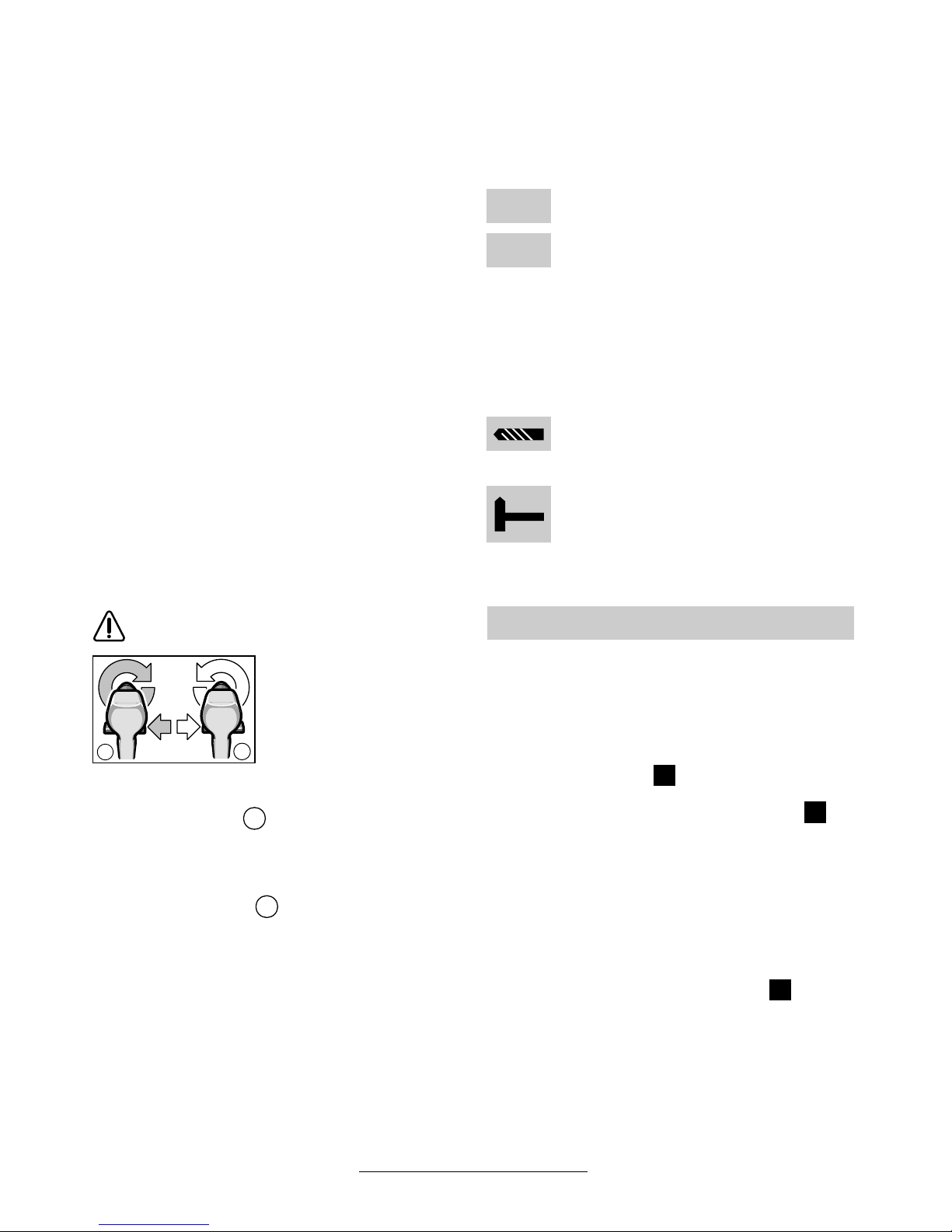
Umschalten der Drehrichtung
Den Drehrichtungsumschalter 5 nur bei
Stillstand betätigen.
Mit dem Drehrichtungsumschalter 5 wird die
Drehrichtung der Maschine umgeschaltet. Bei
betätigtem Ein-/Ausschalter 4 ist dies jedoch
nicht möglich.
Drehrichtung rechts ( )
Den Drehrichtungsumschalter nach links bis zum
Anschlag durchdrücken (Normalbetrieb: Bohren,
Eindrehen von Schrauben etc.).
Drehrichtung links ( )
Den Drehrichtungsumschalter nach rechts bis
zum Anschlag durchdrücken (Lösen bzw. Herausdrehen von Schrauben und Muttern).
Drehmoment einstellen
Im praktischen Versuch ist zu ermitteln, mit welcher der 15 Einstellungen des Drehmoment-Einstellrings 2 die Schrauben bündig in das Material
eingedreht werden.
Schwache Einstellung, z. B. kleine
Schrauben, weiche Werkstoffe.
Starke Einstellung, z. B. große Schrauben, harte Werkstoffe.
Bei richtiger Einstellung öffnet die Überrastkupplung, sobald die Schraube bündig in das Material
eingedreht bzw. das eingestellte Drehmoment erreicht ist. Beim Herausdrehen eine höhere Einstellung wählen, bzw. auf das Symbol „Bohren“
stellen.
Bohren und Schlagbohren
Bohren
Den Drehmoment-Einstellring 2 auf das
Symbol „Bohren“ stellen.
Schlagbohren (GSB 12–24 VE-2)
Den Drehmoment-Einstellring 2 auf das
Symbol „Hammerbohren“ stellen.
■ Vor allen Arbeiten am Gerät den Akku her-
ausnehmen.
Das Bohrfutter ist gegen das Lösen von der Bohrspindel mit der Sicherungsschraube 14 gesi-
chert. Das Bohrfutter ganz öffnen und die Sicherungsschraube 14 (Achtung Linksgewinde!)
vollständig herausschrauben (siehe Bild ).
Bohrfutter lösen (siehe Bild )
Die Maschine auf eine standfeste Unterlage
(z. B. Werkbank) legen. Die Maschine festhalten
und das Bohrfutter wie eine Schraube durch
Linksdrehen lösen (
➊). Ein festsitzendes Bohr-
futter wird durch einen Schlag auf den langen
Schaft des Innensechskantschlüssels 13 gelöst.
Bohrfutter festziehen (siehe Bild )
Die Montage des Bohrfutters erfolgt in umgekehrter Reihenfolge (
➋
).
Softgrip
Die rückseitig angebrachte Griff-Fläche 10 (Softgrip) erhöht die Abrutschsicherheit und sorgt dadurch für bessere Griffigkeit und Handlichkeit des
Gerätes.
Durch die Gummierung wird gleichzeitig eine vibrationshemmende Wirkung erzielt.
■ Verwenden Sie nur zum Schraubenkopf passende Schrauberklingen/Bits.
■ Bei Eindrehen größerer, längerer Schrauben
in harten Werkstoffen am besten vorbohren.
■ Beim Bohren in Metall nur einwandfreie geschärfte HSS-Bohrer (HSS = HochleistungsSchnell-Schnittstahl) verwenden. Entsprechende Qualität garantiert das Bosch-Zubehör-Programm.
b
a
a
b
1
15
Bohrfutter wechseln
Arbeitshinweise
Tipps
E
C
D
9 • 2 609 932 156 • 03.04

Deutsch - 5
■ Vor allen Arbeiten am Gerät den Akku her-
ausnehmen.
☞
Gerät und Lüftungsschlitze stets sauber
halten, um gut und sicher zu arbeiten.
Kohlebürstenwechsel (siehe Bild )
Bei verbrauchten Kohlebürsten schaltet das
Elektrowerkzeug selbsttätig ab. Zum Wechseln
der Schleifkohlen die Schrauben lösen und die
Abdeckkappen 15 abnehmen. Einen Schrauben-
dreher o. Ä. in die Lasche der Schleifkohlenhalterung 16 stecken und diese vorsichtig aushebeln.
Die verbrauchte Kohlebürste herausnehmen und
ersetzen. Die neue Kohlebürste kann auch um
180° gedreht eingesetzt werden. Neue Kohlebürste bis zum Klicken leicht nach unten drücken.
Anschließend die Abdeckkappen 15 wieder montieren.
Sollte das Gerät trotz sorgfältiger Herstellungsund Prüfverfahren einmal ausfallen, ist die Reparatur von einer autorisierten Kundendienststelle
für Bosch-Elektrowerkzeuge ausführen zu lassen.
Bei allen Rückfragen und Ersatzteilbestellungen
bitte unbedingt die 10-stellige Bestellnummer laut
Typenschild des Gerätes angeben.
Rohstoffrückgewinnung statt Müllentsorgung
Gerät, Zubehör und Verpackung sollten einer
umweltgerechten Wiederverwertung zugeführt
werden.
Diese Anleitung ist aus chlorfrei gefertigtem Recycling-Papier hergestellt.
Zum sortenreinen Recycling sind Kunststoffteile
gekennzeichnet.
Nickel-Cadmium-Akku:
Wenn Ihr Produkt mit einem Nickel-CadmiumAkku ausgerüstet ist,
muss der Akku gesammelt, recycelt oder auf
umweltfreundliche Weise
entsorgt werden.
Nickel-MetallhydridAkku: Wenn Ihr Produkt
mit einem Nickel-Metallhydrid-Akku ausgerüstet
ist, kann der Akku mit dem
kommunalen Abfallsystem für feste Abfallstoffe
entsorgt werden.
Defekte oder verbrauchte Akkus müssen gemäß
Richtlinie 91/157/EWG recycelt werden.
Nicht mehr gebrauchsfähige Akkus/Batterien
können direkt abgegeben werden bei:
Deutschland
Recyclingzentrum Elektrowerkzeuge
Osteroder Landstraße 3
37589 Kalefeld
Schweiz
Batrec AG
3752 Wimmis BE
In Deutschland sind nicht mehr gebrauchsfähige
Geräte zum Recycling beim Handel abzugeben
oder (ausreichend frankiert) direkt einzuschicken
an:
Recyclingzentrum Elektrowerkzeuge
Osteroder Landstraße 3
37589 Kalefeld
Wartung und Reinigung
F
Umweltschutz
10 • 2 609 932 156 • 03.04

Deutsch - 6
Messwerte ermittelt entsprechend EN 50 144.
GSR: Der A-bewertete Schalldruckpegel des Ge-
rätes ist typischerweise kleiner als 70 dB (A).
Der Geräuschpegel beim Arbeiten kann
85 dB (A) überschreiten.
Gehörschutz tragen!
Die Hand-Arm-Vibration ist typischerweise niedriger als 2,5 m/s
2
.
GSB: Der A-bewertete Geräuschpegel des Gerätes beträgt typischerweise: Schalldruckpegel
89 dB (A); Schallleistungspegel 102 dB (A).
Gehörschutz tragen!
Die bewertete Beschleunigung beträgt typischerweise 7,5 m/s
2
.
www.powertool-portal.de, das Internetportal
für Handwerker und Heimwerker
www.ewbc.de, der Informations-Pool für Handwerk und Ausbildung
Deutschland
Robert Bosch GmbH
Servicezentrum Elektrowerkzeuge
Zur Luhne 2
37589 Kalefeld
✆ Service:....................................... 01 80 - 3 35 54 99
Fax
............................................. +49 (0) 55 53 / 20 22 37
✆ Kundenberater: ...................... 01 80 - 3 33 57 99
Österreich
ABE Service GmbH
Jochen-Rindt-Straße 1
1232 Wien
✆ Service:..................................... +43 (0)1 / 61 03 80
Fax
................................................. +43 (0)1 / 61 03 84 91
✆ Kundenberater:............. +43 (0)1 / 797 22 3066
E-Mail: abe@abe-service.co.at
Schweiz
✆ Service:................................. +41 (0)1 / 8 47 16 16
Fax:
.................................................. +41 (0)1 / 8 47 16 57
✆ Kundenberater............................... 0 800 55 11 55
Wir erklären in alleiniger Verantwortung, dass dieses Produkt mit den folgenden Normen oder normativen Dokumenten übereinstimmt: EN 50 144
(Akku-Geräte) bzw. EN 60 335 (Akku-Ladegeräte) gemäß den Bestimmungen der Richtlinien
73/23/EWG, 89/336/EWG, 98/37/EG.
03
Dr. Egbert Schneider Dr. Eckerhard Strötgen
Senior Vice President Head of Product
Engineering Certification
Robert Bosch GmbH, Geschäftsbereich Elektrowerkzeuge
Änderungen vorbehalten
Geräusch-/Vibrationsinformation Service und Kundenberater
Konformitätserklärung
11 • 2 609 932 156 • 03.04

English - 1
Tool Specifications
Cordless screwdriver GSR 12 VE-2 14,4 VE-2 18 VE-2 24 VE-2
Order number 0 601 ... 912 5.. 912 4.. 912 3.. 912 2..
No-load speed
1st gear [rpm] 0–400 0 – 400 0–400 0–400
2nd gear [rpm] 0–1 400 0–1 400 0–1 300 0–1 300
Torque adjustment range [Nm] 2–10 2–10 2–10 2–10
Torque, max.
Soft screwdriving case [Nm] 26 30 38 44
Hard screwdriving case [Nm] 65 70 80 85
Drilling dia., steel, max. [mm] 13 13 13 16
Drilling dia., wood, max. [mm] 32 35 38 40
Screw diameter, max. [mm] 8 10 12 14
Chuck clamping range [mm] 1.5 – 13 1.5–13 1.5–13 1.5–13
Drill spindle thread 1/2 " 1/2 " 1/2 " 1/2 "
Weight without battery, approx. [kg] 1.6 1.6 1.6 1.6
Cordless impact drill and
screwdriver
GSB 12 VE-2 14,4 VE-2 18 VE-2 24 VE-2
Order number 0 601 ... 913 5.. 913 4.. 913 3.. 913 2..
No-load speed
1st gear [rpm] 0–500 0 – 500 0–500 0–500
2nd gear [rpm] 0–1 700 0–1 750 0–1 800 0–1 800
Impact rate [bpm] 0 – 21 000 0 – 21 000 0–21 000 0–21 000
Torque adjustment range [Nm] 1.5 – 9 1.5–9 1.5–9 1.5–9
Torque, max.
Soft screwdriving case [Nm] 22 24 28 34
Hard screwdriving case [Nm] 60 65 70 75
Drilling dia., steel, max. [mm] 13 13 13 16
Drilling dia., wood, max. [mm] 30 32 35 38
Drilling dia., masonry, max. [mm] 10 12 14 16
Screw diameter, max. [mm] 8 8 10 12
Chuck clamping range [mm] 1.5 – 13 1.5–13 1.5–13 1.5–13
Drill spindle thread 1/2 " 1/2 " 1/2 " 1/2 "
Weight without battery, approx. [kg] 1.8 1.8 1.9 1.9
Battery
Temperature control NTC NTC NTC NTC
Rated voltage [V=] 12 14.4 18 24
Capacity NiCd [Ah] 2.4 2.4 2.0 2.0
Weight NiCd, approx. [kg] 0.7 0.8 0.9 1.4
Capacity NiMH [Ah] 2.6 2.6 2.6 2.6
Weight NiMH, approx. [kg] 0.7 0.8 1.0 1.3
Please observe the order number of your machine. The trade names of the individual machines may vary.
12 • 2 609 932 156 • 03.04
English - 2
1 Gear selector
2 Torque setting ring
3 Keyless chuck
4 On/Off switch
5 Rotational direction switch
6 Battery*
7 Universal bit holder*
8 Battery unlocking button
9 Auxiliary handle*
10 Soft grip
11 Clamping band*
12 Screwdriver attachment (bit)*
13 Allen key*
14 Locking screw
15 Cover lid
16 Brush holder
* Not all of the accessories illustrated or described are
included as standard delivery.
GSR: The machine is intended for the screwing
in and loosening of screws as well as for drilling
in wood, metal, ceramic and plastic.
GSB: The machine is intended for screwing in
and loosening screws, for drilling in wood, metal,
ceramic and plastic and for impact drilling in brick,
concrete and stone.
Working safely with this machine is possible only when the
operating and safety information
are read completely and the instructions contained therein are
strictly followed. In addition, the
general safety notes in the enclosed booklet
must be observed.
■ Wear safety goggles.
■ For long hair, wear hair protection. Work only
with closely fitting clothes.
■ Before each use, check the machine and bat-
tery. If damage is detected, do not use the machine. Have repairs performed only by a qualified technician. Never open the machine yourself.
■ Before any work on the machine itself (e. g.
maintenance, tool change, etc.) as well as
when transporting and storing, always set
the rotational direction switch to the centre
position. Otherwise danger of injury is given
when unintentionally actuating the On/Off
switch.
■ Convince yourself before using that the battery
is securely seated in the machine.
■ Do not strain the machine so heavily that it
comes to a standstill.
■ GSB 18 VE-2 /GSB 24 VE-2 /GSR 18 VE-2 /
GSR 24 VE-2: Operate the machine only with
the auxiliary handle 9.
When working with the machine, always hold it
firmly with both hands and provide for a secure
stance.
■ Use appropriate detectors to determine if
utility lines are hidden in the work area or
call the local utility company for assistance.
Contact with electric lines can lead to fire and
electric shock. Damaging a gas line can lead
to explosion. Penetrating a water line causes
property damage.
■ Hold the machine tightly: When driving in
screws, high reaction moments can briefly occur.
■ Secure the workpiece. A workpiece clamped
with clamping devices or in a vice is held more
secure than by hand.
■ Never allow children to use the machine.
■ Bosch is only able to ensure perfect operation
of the machine if the original accessories intended for it are used.
Battery and Battery Charger
■ The enclosed operating instructions for the
battery charger must be read carefully!
■ Do not open the battery, and protect it from impact. Store in a dry and frost-free place.
■ Allow a heated battery to cool before charging.
■ Protect the battery from heat and fire: Danger
of explosion! Do not place the battery on radiators or expose to strong sun rays for a longer
time; temperatures over 50 °C cause damage.
■ Do not dispose of the battery in household
waste or discard into fire or water.
Machine Elements
Intended Use
For Your Safety
13 • 2 609 932 156 • 03.04
English - 3
Battery Charging
A battery that is new or has not been used for a
longer period does not develop its full capacity
until after approximately 5 charging /discharging
cycles.
To remove the battery 6, press the unlocking buttons 8 and pull out the battery downwards. Do not
exert any force.
The battery is equipped with an NTC temperature
control which allows charging only within a temperature range of between 0 °C and 45 °C.
A long battery service life is achieved in this manner.
A significantly reduced working period after
charging indicates that the batteries are used and
must be replaced.
■ Observe the notes on environmental protection.
Loosen the handle by turning to the left. Rotate
the auxiliary handle 9 and adapt to the working
position. Make sure that the clamping band 11 of
the auxiliary handle remains in the groove.
Afterwards tighten the handle again by turning in clockwise direction.
Open the drill chuck until the tool can be inserted.
Insert the tool.
Firmly tighten the sleeve of the keyless chuck 3
by hand until the locking action (“click”) is no
longer heard. This automatically locks the chuck.
Rotate the sleeve in the reverse direction to remove the tool.
Screwdriving (see figure )
Clamp the bit 12 directly into the drill chuck. For
quick changes, using the universal bit holder 7 is
recommended.
Inserting the Battery
Set the rotational direction switch 5 to the centre
position = lock-off and allow the charged battery 6 to engage into the handle.
Switching On and Off
To start the machine, press the On/Off switch 4
and keep it depressed.
The machine runs with variable
speed between 0 and maximum,
depending on the pressure applied
to the On / Off switch 4. Light pres-
sure results in a low rotational
speed thus allowing smooth, controlled starts. Do not strain the machine so heavily that it comes to a
standstill.
To switch off the machine, release the On / Off
switch 4.
Electric Brake
When releasing the On/Off switch 4 the speed of
the drill chuck is reduced to a stop, thus preventing the run-on of the tool.
For screwdriving applications, wait until the screw
is flush with the material and then release the On/
Off switch 4. The screw head does not penetrate
into the material then.
Gear Selection, Mechanical
Two speed ranges can be preselected with the
gear selector 1:
1st gear: Low rotational speed, high power.
2nd gear: High rotational speed, less power.
The gear setting can be changed while the ma-
chine is running, however, not while under load.
It is recommended to carry out the switching
while the machine is at a standstill. If the gear selector 1 cannot be slid into the end position while
the machine is at a standstill, turn the chuck
somewhat or briefly press the On/Off switch 4.
Before Putting into Operation
Auxiliary Handle (see figure )
(GSB 12 –24 VE-2/
GSR 18 –24 VE-2)
Changing the Tool
A
B
Initial Operation
14 • 2 609 932 156 • 03.04

English - 4
Fully Automatic Spindle Locking
(Auto-Lock)
The drill spindle is locked when the On/Off
switch 4 is not pressed.
This makes quick and easy changing of the tool
in the drill chuck possible.
The locked drill chuck enables retightening of
projecting screws by using the switched-off machine as a screwdriver.
Reversing the Rotational Direction
Operate the rotational direction
switch 5 only at a standstill.
The rotational direction
switch 5 is used to re-
verse the rotational direction of the machine. However, this is not possible
with the On/Off switch 4
actuated.
Right Rotation ( )
Turn the rotational direction switch through to the
left stop (normal operation: drilling, screwdriving,
etc.).
Left Rotation ( )
Press the rotational direction switch through to
the right stop (for loosening and unscrewing
screws and nuts).
Setting the Torque
Carry out a practical test to determine with which
of the 15 settings of the torque setting ring 2 the
screws are driven flush into the material.
Low setting, e. g., small screws, soft
materials.
High setting, e. g., large screws, hard
materials.
With the correct setting, the clutch disengages as
soon as the screw is driven flush into the material
or the set torque is reached. Select a higher setting when driving out screws, or set to the “Drilling” symbol.
Drilling and Impact Drilling
Drilling
Set the torque setting ring 2 to the “Drilling” symbol.
Hammer Drilling (GSB 12–24 VE-2)
Set the torque setting ring 2 to the
“Hammer Drilling” symbol.
■ Before any work on the machine itself, re-
move the battery.
The locking screw 14 secures the drill chuck
against loosening from the drill spindle. Fully
open the chuck and completely unscrew the
locking screw 14 (Note: left-handed thread!)
(see figure ).
Loosening the Drill Chuck
(see figure )
Place the machine on a stable surface (e. g.
workbench). Hold the machine firmly and loosen
the chuck by turning to the left, as when unscrewing a screw (
➊). Loosen a tight chuck by giving
the long end of the Allen key 13 a sharp blow.
Tightening the Drill Chuck
(see figure )
The drill chuck is mounted in reverse order (➋).
Soft grip
The gripping surface 10 on the rear of the handle
(soft grip) reduces the danger of slipping and
thereby improves the grip on the machine and the
handling.
At the same time, the rubber coating achieves a
vibration-reducing effect.
■ Use only screwdriver bits that fit properly in the
head of the screw.
■ When driving in larger and/or longer screws in
hard material, it is advisable to drill a pilot hole
first.
■ For drilling in metal, use only perfectly sharpened HSS drills. The appropriate quality is
guaranteed by the Bosch accessories program.
b
a
a
b
1
15
Replacing the Drill Chuck
Operating Instructions
Tips
E
C
D
15 • 2 609 932 156 • 03.04
English - 5
■ Before any work on the machine itself, re-
move the battery.
☞
For safe and proper working, always keep
the machine and the ventilation slots clean.
Brush Replacement (see figure )
When the brushes are worn the power tool
switches off automatically. For replacement of
the carbon brushes, loosen the screws and remove the cover lids 15. Insert a screwdriver or
similar into the notch of the brush holder 16 and
carefully pry it out. Remove the used carbon
brush and replace. The new carbon brush can
also be inserted when turned by 180°. Lightly
press down the new carbon brush until it clicks.
Afterwards mount the cover lids 15 again.
If the machine should fail despite the care taken
in manufacturing and testing procedures, repair
should be carried out by an after-sales service
centre for Bosch power tools.
In all correspondence and spare parts orders,
please always include the 10-digit order number
given on the nameplate of the machine.
Recycle raw materials instead of disposing as
waste
The machine, accessories and packaging should
be sorted for environmental-friendly recycling.
These instructions are printed on recycled paper
manufactured without chlorine.
The plastic components are labelled for categorized recycling.
Nickel-cadmium-battery: If your product is
equipped with a nickelcadmium-battery, the battery must be collected, recycled or disposed of in an
environmentally-friendly
way.
Nickel-metalhydrid-battery: If your product is
equipped with a nickelmetalhydrid-battery, the
battery can be disposed of
through the local waste
disposal system for solid
waste materials.
Defective or worn out batteries must be recycled
according to the guidelines 91/157/EEC.
Batteries no longer suitable for use can be
directly returned at:
Great Britain
Robert Bosch Ltd. (B.S.C.)
P.O. Box 98
Broadwater Park
North Orbital Road
Denham-Uxbridge
Middlesex UB 9 5HJ
✆ Service............................ +44 (0)18 95 / 83 87 82
✆ Advice line.................... +44 (0) 18 95 / 83 87 91
Fax
............................................. +44 (0)18 95 / 83 87 89
Maintenance and Cleaning
F
Environmental Protection
16 • 2 609 932 156 • 03.04

English - 6
Measured values determined according to
EN 50 144.
GSR: Typically the A-weighted sound pressure
level of the product is less than 70 dB (A).
The noise level when working can exceed
85 dB (A).
Wear hearing protection!
The typical hand/arm vibration is below 2.5 m/s
2
.
GSB: Typically the A-weighted noise levels of the
product are: sound pressure level: 89 dB (A);
sound power level: 102 dB (A).
Wear hearing protection!
The typically weighted acceleration is 7.5 m/s
2
.
Great Britain
Robert Bosch Ltd. (B.S.C.)
P.O. Box 98
Broadwater Park
North Orbital Road
Denham-Uxbridge
Middlesex UB 9 5HJ
✆ Service............................ +44 (0)18 95 / 83 87 82
✆ Advice line.................... +44 (0) 18 95 / 83 87 91
Fax
............................................. +44 (0)18 95 / 83 87 89
Ireland
Beaver Distribution Ltd.
Greenhills Road
Tallaght-Dublin 24
✆ Service................................... +353 (0)1 / 414 9400
Fax
.................................................... +353 (0)1 / 459 8030
Australia
Robert Bosch Australia Ltd.
RBAU/SPT2
1555 Centre Road
P.O. Box 66 Clayton
3168 Clayton/Victoria
✆ ................................................ +61 (0)1 / 800 804 777
Fax
................................................ +61 (0)1 / 800 819 520
www.bosch.com.au
E-Mail: CustomerSupportSPT@au.bosch.com
New Zealand
Robert Bosch Limited
14-16 Constellation Drive
Mairangi Bay
Auckland
New Zealand
✆ ..................................................... +64 (0)9 / 47 86 158
Fax
..................................................... +64 (0)9 / 47 82 914
We declare under our sole responsibility that this
product is in conformity with the following standards or standardization documents. EN 50 144
(Battery powered products) and EN 60 335 (Battery charger) according to the provisions of the directives 73/23/EEC, 89/336/EEC, 98/37/EC.
03
Dr. Egbert Schneider Dr. Eckerhard Strötgen
Senior Vice President Head of Product
Engineering Certification
Robert Bosch GmbH, Geschäftsbereich Elektrowerkzeuge
Subject to change without notice
Noise/Vibration Information
Service and Customer
Assistance
Declaration of Conformity
17 • 2 609 932 156 • 03.04

Français - 1
Caractéristiques techniques
Perceuse-visseuse sans fil GSR 12 VE-2 14,4 VE-2 18 VE-2 24 VE-2
Référence 0 601 ... 912 5.. 912 4.. 912 3.. 912 2..
Régime à vide
1
ère
vitesse [tr/min] 0 – 400 0–400 0–400 0– 400
2
ème
vitesse [tr/min] 0 – 1 400 0 – 1 400 0 – 1 300 0 – 1 300
Plage de réglage du couple [Nm] 2–10 2–10 2–10 2–10
Couple, max.
Vissages faciles [Nm] 26 30 38 44
Vissages difficiles [Nm] 65 70 80 85
Ø perçage dans l’acier, max. [mm] 13 13 13 16
Ø perçage dans le bois, max. [mm] 32 35 38 40
Ø des vis, max. [mm] 8 10 12 14
Fixation du mandrin de perçage [mm] 1,5–13 1,5–13 1,5–13 1,5–13
Fixation de la broche 1/2 " 1/2 " 1/2 " 1/2 "
Poids sans accumulateur, env. [kg] 1,6 1,6 1,6 1,6
Visseuse-perceuse à
percussion sans fil
GSB 12 VE-2 14,4 VE-2 18 VE-2 24 VE-2
Référence 0 601 ... 913 5.. 913 4.. 913 3.. 913 2..
Régime à vide
1
ère
vitesse [tr/min] 0 – 500 0–500 0–500 0– 500
2
ème
vitesse [tr/min] 0 – 1 700 0 – 1 750 0 – 1 800 0 – 1 800
Fréquence de frappe [tr/min] 0–21 000 0–21 000 0–21 000 0–21 000
Plage de réglage du couple [Nm] 1,5 – 9 1,5–9 1,5–9 1,5–9
Couple, max.
Vissages faciles [Nm] 22 24 28 34
Vissages difficiles [Nm] 60 65 70 75
Ø perçage dans l’acier, max. [mm] 13 13 13 16
Ø perçage dans le bois, max. [mm] 30 32 35 38
Ø perçage dans la maçonnerie,
max.
[mm] 10 12 14 16
Ø des vis, max. [mm] 8 8 10 12
Fixation du mandrin de perçage [mm] 1,5–13 1,5–13 1,5–13 1,5–13
Fixation de la broche 1/2 " 1/2 " 1/2 " 1/2 "
Poids sans accumulateur, env. [kg] 1,8 1,8 1,9 1,9
Accumulateur
Contrôle de température NTC NTC NTC NTC
Tension nominale [V=] 12 14,4 18 24
Capacité NiCd [Ah] 2,4 2,4 2,0 2,0
Poids NiCd, env. [kg] 0,7 0,8 0,9 1,4
Capacité NiMH [Ah] 2,6 2,6 2,6 2,6
Poids NiMH, env. [kg] 0,7 0,8 1,0 1,3
Faire attention au numéro de référence de la machine. Les désignations commerciales des différentes machines peuvent
varier.
18 • 2 609 932 156 • 03.04

Français - 2
1 Commutateur de vitesse
2 Bague de réglage du couple
3 Mandrin à serrage rapide
4 Interrupteur Marche/Arrêt
5 Commutateur du sens de rotation
6 Accumulateur*
7 Porte-embout universel*
8 Touche de déverrouillage de l’accumulateur
9 Poignée supplémentaire*
10 Point d’appui souple (antidérapant)
11 Anneau de serrage*
12 Embout tournevis*
13 Clé mâle pour vis à six pans creux*
14 Vis de retenue
15 Cache
16 Support de balais de charbon
* Les accessoires reproduits ou décrits ne sont pas
forcément fournis avec la machine.
GSR : L’appareil est conçu pour le vissage et le
dévissage des vis ainsi que pour le perçage dans
le bois, le métal, le céramique et les matières
plastiques.
GSB : L’appareil est conçu pour le vissage et dévissage des vis, pour le perçage dans le bois, le
métal, la céramique et les matières plastiques
ainsi que pour le perçage à percussion dans la
brique, le béton et dans la roche.
Pour travailler sans risque avec
cet appareil, lire intégralement
au préalable les instructions
d’utilisation et les remarques
concernant la sécurité. Respec-
ter scrupuleusement les indications et les consignes qui y sont données.
Respecter en plus les indications générales
de sécurité se trouvant dans le cahier ci-joint.
■ Porter des lunettes de protection.
■ Les personnes portant les cheveux longs doi-
vent se munir d’un protège-cheveux. Ne travailler qu’avec des vêtements près du corps.
■ Avant chaque utilisation, vérifier l’appareil et
l’accumulateur. Ne jamais mettre en marche
un appareil endommagé. Les réparations ne
doivent être confiées qu’à un spécialiste. Ne
jamais ouvrir l’appareil soi-même.
■ Avant d’effectuer des travaux sur l’appareil
(p. ex. travaux d’entretien, changement
d’outils, etc.) et avant de le transporter ou
stocker, toujours mettre le commutateur de
sens de rotation en position médiane. Si-
non, il y a risque de blessure lorsqu’on appuie
par mégarde sur l’interrupteur Marche/Arrêt.
■ Avant utilisation, toujours contrôler que l’accumulateur est correctement en place.
■ Ne jamais charger l’appareil jusqu’à provoquer
son arrêt complet.
■ GSB 18 VE-2 /GSB 24 VE-2 /GSR 18 VE-2 /
GSR 24 VE-2 : N’utilisez votre appareil
qu’avec la poignée supplémentaire 9.
Pendant le travail avec cet appareil, le tenir
toujours fermement avec les deux mains.
Adopter une position stable et sûre.
■ Utiliser des détecteurs appropriés afin de
déceler des conduites cachées ou consulter les entreprises d’approvisionnement locales.
Un contact avec des conduites d’électricité
peut provoquer un incendie ou un choc électrique. L’endommagement d’une conduite de
gaz peut provoquer une explosion. La perforation d’une conduite d’eau provoque des dégâts
matériels.
■ Bien tenir la machine : Lors du vissage, il peut
y avoir des couples de réaction élevés.
■ Bloquer la pièce à travailler. Une pièce à tra-
vailler serrée par des dispositifs de serrage ou
dans un étau est fixée de manière plus sûre
que si elle est seulement tenue de la main.
■ Ne jamais permettre aux enfants d’utiliser cet
appareil.
■ Bosch ne peut garantir un fonctionnement impeccable que si les accessoires Bosch d’origine prévus pour cet appareil sont utilisés.
Accumulateur et chargeur
■ Lire absolument le mode d’emploi du chargeur ci-joint !
■ Ne pas ouvrir l’accumulateur. Le protéger de
tout choc mécanique. L’entreposer dans un
endroit sec et à l’abri du gel.
■ Avant de recharger un accumulateur échauffé,
le laisser refroidir.
Eléments de la machine
Utilisation conformément à la
destination de l’appareil
Pour votre sécurité
19 • 2 609 932 156 • 03.04
Français - 3
■ Protéger l’accumulateur contre toute exposition à la chaleur ou au feu : risque d’explosion ! Ne pas poser l’accumulateur sur un
corps chaud (radiateur, par exemple). Ne pas
l’exposer trop longtemps à un fort ensoleillement. Les températures dépassant 50 °C lui
sont néfastes.
■ Ne pas jeter l’accu dans les ordures ménagères, ni dans les flammes ou dans l’eau.
Recharge de l’accumulateur
Un accu neuf ou un accu qui n’a pas été utilisé
pendant une période assez longue, n’atteint sa
pleine puissance qu’après environ cinq cycles de
charge et de décharge.
Pour sortir l’accumulateur 6, appuyer sur les boutons de déverrouillage 8 et retirer l’accumulateur
vers le bas. Ne pas forcer.
L’accumulateur est doté d’un dispositif de surveillance de la température NTC ne permettant la
charge que dans une plage de température comprise entre 0 °C et 45 °C. La longévité de l’accumulateur s’en trouve ainsi accrue.
Si le temps de service des accus se raccourcit
considérablement après un processus de
charge, cela indique que les accus sont usés et
qu’ils doivent être remplacés.
■ Observer les consignes relatives à la protection de l’environnement.
Imprimer au manche de la poignée une rotation
vers la gauche. Faire pivoter la poignée supplémentaire 9 et la régler en fonction de la position
de travail. Faire attention à ce que l’anneau de
serrage 11 de la poignée supplémentaire reste
dans la rainure.
Serrer ensuite la manette de nouveau à fond
en tournant vers la droite.
Ouvrir le mandrin de perçage de sorte que l’outil
puisse être monté. Monter l’outil.
Visser fermement la douille du mandrin à serrage
rapide 3 à la main, jusqu’à ce qu’aucun bruit correspondant au passage d’un cran ne soit plus
audible (« cliquetis »). Ceci permet le verrouillage automatique du mandrin porte-foret.
Tourner le corps dans le sens inverse pour retirer
l’outil.
Vissage (voir figure )
Fixer l’embout 12 directement dans le mandrin.
Pour le remplacement rapide, nous conseillons
l’utilisation du porte-embout universel 7.
Mise en place de l’accumulateur
Mettre le commutateur du sens de rotation 5
dans la position médiane = verrouillage de mise
en fonctionnement et faire encliqueter l’accu
chargé 6 dans la poignée.
Mise en fonctionnement/Arrêt
Afin de mettre l’appareil en fonctionnement,
appuyer sur l’interrupteur Marche/Arrêt 4 et le
maintenir appuyé.
En fonction de la pression exercée
sur l’interrupteur Marche/Arrêt 4,
l’appareil fonctionne à une vitesse
comprise entre 0 et le maximum.
Une légère pression fait tourner
l’appareil à petite vitesse, ce qui
permet un démarrage précis et en
douceur. Ne pas trop solliciter l’appareil qui risque sinon de s’arrêter.
Afin d’arrêter l’appareil, relâcher l’interrupteur
Marche/Arrêt 4.
Frein de ralentissement
Lorsqu’on relâche l’interrupteur Marche /Arrêt 4,
le mandrin est freiné, ce qui évite un fonctionnement par inertie de l’outil.
Lors de travaux de vissage, ne relâcher l’interrupteur Marche/Arrêt 4 que lorsque la vis est enfoncée à ras dans le matériau. La tête de vis ne pénètre alors pas le matériau.
Avant la mise en service
Poignée supplémentaire (voir
figure ) (GSB 12 –24 VE-2/
GSR 18 –24 VE-2)
A
Changement de l’outil
Mise en service
B
20 • 2 609 932 156 • 03.04
Français - 4
Commutation mécanique de la vitesse
Le commutateur de vitesse 1 permet de sélec-
tionner deux plages de vitesse de rotation :
1
ère
vitesse : Petite vitesse, force élevée.
2
ème
vitesse : Vitesse élevée, force faible.
Le passage d’une vitesse à l’autre peut s’effectuer lorsque l’appareil est en marche, mais pas
en charge. Il est cependant recommandé de ne
changer de vitesse qu’à l’arrêt total de l’appareil.
Si, une fois l’appareil arrêté, le sélecteur de vitesse 1 refuse de gagner sa position finale, tour-
ner en plus légèrement le mandrin de perçage et
appuyer brièvement sur l’interrupteur Marche/Arrêt 4.
Blocage de broche automatique
(Auto-Lock)
Lorsque l’interrupteur Marche/Arrêt 4 n’est pas
appuyé, la broche de perçage est bloquée.
Ceci permet de remplacer l’outil utilisé dans le
mandrin de manière rapide, aisée et facile.
Le blocage du mandrin permet de resserrer les
vis en saillie, en utilisant la machine à l’arrêt
comme d’un tournevis.
Inversion du sens de rotation
N’actionner le commutateur du sens de
rotation 5 qu’à l’arrêt total de l’appareil.
Le sens de rotation de
l’appareil peut être modifié à l’aide du commutateur du sens de rotation 5. Cela n’est toute-
fois pas possible en
actionnant l’interrupteur
Marche/Arrêt 4.
Rotation à droite ( )
Pousser à fond le commutateur du sens de rotation vers la gauche (service normal : perçage,
vissage, etc.).
Rotation à gauche ( )
Repousser à fond le commutateur du sens de rotation vers la droite « Rotation à droite » (pour les
travaux de desserrage, de dévissage de vis et
d’écrous).
Réglage du couple
En effectuant des essais pratiques, déterminer le
réglage approprié parmi les 15 positions possibles de la bague de réglage du couple 2 afin de
pouvoir visser correctement les vis afin que leur
tête affleure le matériau.
Couple réduit p. ex. petites vis, matériaux tendres.
Couple élevé p. ex. grandes vis, matériaux durs.
Le réglage est correct lorsque l’embrayage à
crans est déclenché dès que la tête de la vis affleure le matériau ou que le couple préréglé est
atteint. Pour dévisser, choisir un réglage plus
élevé, ou régler sur le symbole « Perçage ».
Perçage et perçage à percussion
Perçage
Positionner la bague de réglage du couple 2 sur le symbole « Perçage ».
Perçage en frappe
(GSB 12–24 VE-2)
Positionner la bague de réglage du couple 2 sur le symbole « Perçage en
frappe ».
■ Avant toute intervention sur l’appareil pro-
prement dit, retirer l’accumulateur.
Pour ne pas se déloger de l’unité de perçage, le
mandrin est équipé d’une vis de retenue 14.
Ouvrir complètement le mandrin et dévisser totalement la vis de retenue 14 (Attention, filetage à
gauche !) (voir figure ).
Desserrer le mandrin (voir figure )
Poser la machine sur un support stable (p. ex.
établi). Maintenir la machine et dévisser le mandrin comme si c’était une vis, en tournant à gauche (
➊). Un mandrin qui serait trop serré peut
être desserré en donnant un léger coup sur le
côté le plus long de la clé mâle coudée pour vis à
six pans creux 13.
Serrer le mandrin (voir figure )
Pour monter le mandrin, procéder en sens inverse (
➋
).
b
a
a
b
Changement du mandrin
1
15
E
C
D
21 • 2 609 932 156 • 03.04

Français - 5
Softgrip
La surface arrière de la poignée 10 évite un glissement de la main et permet ainsi une meilleure
maniabilité de l’appareil.
Grâce au revêtement en caoutchouc, les vibrations sont également atténuées.
■ N’utiliser que des lames de tournevis et des
embouts de vissage adaptés à la tête de la vis.
■ Lors du vissage de vis de taille et de longueur
importantes dans des matériaux durs, il est recommandé de percer un avant-trou.
■ Lors de perçage dans les métaux, n’utiliser
que des forets HSS en bon état et bien affûtés
(HSS = aciers super rapides). Le programme
d’accessoires Bosch garantit la qualité des forets.
■ Avant toute intervention sur l’appareil proprement dit, retirer l’accumulateur.
☞
Pour obtenir un travail sûr et satisfaisant,
nettoyer régulièrement l’appareil ainsi que
ses ouïes de refroidissement.
Remplacement des balais de charbon
(voir figure )
Si les balais de charbon sont usés, l’appareil
électroportatif se met de lui-même hors circuit.
Pour effectuer le remplacement des balais de
charbon, dévisser les boulons et retirer les caches 15. Introduire un tournevis ou un outil simi-
laire dans l’attache du support de balais de charbon 16 et s’en servir comme levier pour l’extraire
avec précaution. Retirer le balai de charbon usé
et le remplacer. On peut également mettre en
place le nouveau balai à charbon pivoté sur 180°.
Appuyer légèrement les nouveaux balais de
charbon vers le bas jusqu’à ce qu’ils s’encrantent. Ensuite, remettre les caches 15 en place.
Si, malgré tous les soins apportés à la fabrication
et au contrôle de l’appareil, celui-ci devait avoir
un défaut, la réparation ne doit être confiée qu’à
une station de service après-vente agréée pour
outillage Bosch.
Pour toute demande de renseignements ou commande de pièces de rechange, nous préciser impérativement le numéro de référence à dix chiffres de la machine.
Récupération des matières premières plutôt
qu’élimination des déchets
Les machines, comme d’ailleurs leurs accessoires et emballages, doivent pouvoir suivre chacune une voie de recyclage appropriée.
Ce manuel d’instructions a été fabriqué à partir
d’un papier recyclé blanchi sans chlore.
Nos pièces plastiques ont ainsi été marquées en
vue d’un recyclage sélectif des différents matériaux.
Accumulateur NickelCadmium : Au cas où vo-
tre produit serait équipé
d’un accu Nickel-Cadmium, l’accu doit être récupéré, recyclé ou éliminé
en conformité avec les réglementations se rapportant à l’environnement.
Accumulateur NickelHydrure de métal : Au
cas où votre produit serait
équipé d’un accu NickelHydrure de métal, l’accu
peut être éliminé par le
système communal
chargé de l’élimination
des déchets solides.
Les accus usés ou défectueux doivent être recyclés conformément à la directive 91/157/CEE.
Les accus /piles dont on ne peut plus se servir
peuvent être déposés directement auprès de :
Suisse
Batrec AG
3752 Wimmis BE
Instructions d’utilisation
Conseils d’utilisation
Nettoyage et entretien
F
Instructions de protection de
l’environnement
22 • 2 609 932 156 • 03.04

Français - 6
Valeurs de mesure obtenues conformément à la
norme européenne 50 144.
GSR : La mesure réelle (A) du niveau sonore de
l’outil est inférieure à 70 dB (A).
Le niveau sonore en fonctionnement peut dépasser 85 dB (A).
Munissez-vous d’une protection acoustique !
La vibration de l’avant-bras est en-dessous de
2,5 m/s
2
.
GSB : Les mesures réelles (A) des niveaux sonores de la machine sont : intensité de bruit
89 dB (A). Niveau de bruit 102 dB (A).
Munissez-vous d’une protection acoustique !
L’accélération réelle mesurée est de 7,5 m/s
2
.
France
Information par Minitel 11
Nom : Bosch Outillage
Loc : Saint Ouen
Dépt : 93
Robert Bosch France S.A.
Service Après-vente/Outillage
B.P. 67-50, Rue Ardoin
93402 St. Ouen Cedex
✆ Service conseil client.................... 0143 11 9002
Numéro Vert
.................................... 0 800 05 50 51
Belgique
Robert Bosch S.A.
After Sales Service Outillage
Rue Henri Genesse 1
1070 Bruxelles
✆ ..................................................... +32 (0)2 / 525.50.29
Fax
..................................................... +32 (0)2 / 525.54.30
✆ Service conseil client..... +32 (0)2 / 525.53.07
E-Mail : Outillage.Gereedschappen@be.bosch.com
Suisse
✆ .................................................... +41 (0)1 / 8 47 16 16
Fax
.................................................... +41 (0)1 / 8 47 16 57
✆ Service conseil client................. 0 800 55 11 55
Nous déclarons sous notre propre responsabilité
que ce produit est en conformité avec les normes
ou documents normalisés : EN 50 144 (appareils
sans fil) respectivement EN 60 335 (chargeurs
électriques) conformément aux termes des réglementations 73/23/CEE, 89/336/CEE, 98/37/CE.
03
Dr. Egbert Schneider Dr. Eckerhard Strötgen
Senior Vice President Head of Product
Engineering Certification
Robert Bosch GmbH, Geschäftsbereich Elektrowerkzeuge
Sous réserve de modifications
Bruits et vibrations Service Après-Vente
Déclaration de conformité
23 • 2 609 932 156 • 03.04

Español - 1
Características técnicas
Atornilladora taladradora
accionada por acumulador
GSR 12 VE-2 14,4 VE-2 18 VE-2 24 VE-2
Número de pedido 0 601 ... 912 5.. 912 4.. 912 3.. 912 2..
Revoluciones en vacío
1ª velocidad [min-1] 0–400 0–400 0– 400 0–400
2ª velocidad [min-1] 0–1 400 0–1 400 0–1 300 0–1 300
Ajuste del par de giro [Nm] 2–10 2–10 2–10 2–10
Par de giro, máx.
Unión blanda [Nm] 26 30 38 44
Unión rígida [Nm] 65 70 80 85
Ø de taladro en acero, máx. [mm] 13 13 13 16
Ø de taladro en madera, máx. [mm] 32 35 38 40
Ø de tornillo, máx. [mm] 8 10 12 14
Capacidad de sujeción del
portabrocas
[mm] 1,5–13 1,5–13 1,5–13 1,5–13
Rosca del husillo de taladrar 1/2 " 1/2 " 1/2 " 1/2 "
Peso sin acumulador, aprox. [kg] 1,6 1,6 1,6 1,6
Atornilladora-taladradora de
percusión con acumulador
GSB 12 VE-2 14,4 VE-2 18 VE-2 24 VE-2
Número de pedido 0 601 ... 913 5.. 913 4.. 913 3.. 913 2..
Revoluciones en vacío
1ª velocidad [min-1] 0–500 0–500 0– 500 0–500
2ª velocidad [min-1] 0–1 700 0–1 750 0–1 800 0–1 800
Frecuencia de percusión [min-1] 0–21 000 0–21 000 0–21 000 0–21 000
Ajuste del par de giro [Nm] 1,5–9 1,5–9 1,5–9 1,5–9
Par de giro, máx.
Unión blanda [Nm] 22 24 28 34
Unión rígida [Nm] 60 65 70 75
Ø de taladro en acero, máx. [mm] 13 13 13 16
Ø de taladro en madera, máx. [mm] 30 32 35 38
Ø de taladro en mamposteria, máx. [mm] 10 12 14 16
Ø de tornillo, máx. [mm] 8 8 10 12
Capacidad de sujeción del
portabrocas
[mm] 1,5–13 1,5–13 1,5–13 1,5–13
Rosca del husillo de taladrar 1/2 " 1/2 " 1/2 " 1/2 "
Peso sin acumulador, aprox. [kg] 1,8 1,8 1,9 1,9
Acumulador
Control de temperatura NTC NTC NTC NTC
Tensión nominal [V=] 12 14,4 18 24
Capacidad NiCd [Ah] 2,4 2,4 2,0 2,0
Peso NiCd, aprox. [kg] 0,7 0,8 0,9 1,4
Capacidad NiMH [Ah] 2,6 2,6 2,6 2,6
Peso NiMH, aprox. [kg] 0,7 0,8 1,0 1,3
Preste atención al nº de pedido de su máquina. Las denominaciones comerciales en ciertas máquinas pueden variar.
24 • 2 609 932 156 • 03.04
 Loading...