


D7412G
Table of contents
 Loading...
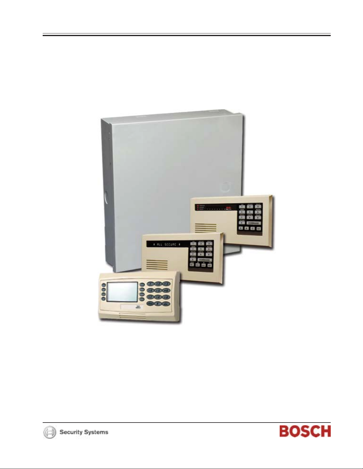
Control Panels D9412G/D7412G/D7212G
Installation & Troubleshooting Quick Reference Guide

D9412G /D7412G/ D7212G
Installation & Troubleshooting Quick Reference Guide
D9412G/D7412G/D7212G Installation & Troubleshooting Quick Reference Guide
Page 2 © 2004 Bosch Security Systems, Inc.43700F

D9412G /D7412G/ D7212G
Contents
Table of Contents
1.0 Introduction ............................................................................................................................................................................................. 5
1.1 Manual Organization ..........................................................................................................................................................................5
1.2 Other Literature Referenced ............................................................................................................................................. 5
2.0 Quick Reference Terminal Description ......................................................................................................................................7
3.0 Troubleshooting .................................................................................................................................................................................... 9
3.1 Introduction ............................................................................................................................................................................. 9
3.2 Problems Found During Self Diagnostics ....................................................................................................................... 9
3.3 Problems Programming the Panel .................................................................................................................................. 1 0
3.4 Problems With Command Centers ................................................................................................................................ 1 1
3.5 Phone Line Trouble .............................................................................................................................................................11
3.6 Communication Failure .....................................................................................................................................................12
3.7 Problems with Points .......................................................................................................................................................... 13
3.7.1 Extra Points ........................................................................................................................................................................... 14
3.8 Problems with the D8125 POPEX Data Expansion Loops ......................................................................................15
3.8.1 Metering the Loops ............................................................................................................................................................ 15
3.9 EMI on Long Wire Runs ...................................................................................................................................................16
3.10 Checking Shielded Cable ................................................................................................................................................16
3.11 Battery and Power Reports ..............................................................................................................................................16
3.12 Watchdog Reset Reports ................................................................................................................................................. 17
3.13 Runaway Reports to the Receiver ................................................................................................................................. 17
3.14 Overloaded Power Supply ................................................................................................................................................ 17
3.15 Service Walk Test ............................................................................................................................................................... 18
3.16 Ground Fault ....................................................................................................................................................................... 2 0
3.16.1 Procedure for Isolating Earth Ground Faults ............................................................................................................... 20
3.17 Panel Buzzer .........................................................................................................................................................................21
4.0 System Wiring Diagrams, Issue A ............................................................................................................................................ 23
4.1 D9412G Control Panel, 1 of 3 ...................................................................................................................................... 2 3
4.2 D9412G Control Panel, 2 of 3 ...................................................................................................................................... 2 4
4.3 D9412G Control Panel, 3 of 3 ...................................................................................................................................... 2 5
4.4 D7412G Control Panel, 1 of 3 ...................................................................................................................................... 2 6
4.5 D7412G Control Panel, 2 of 3 ...................................................................................................................................... 2 7
4.6 D7412G Control Panel, 3 of 3 ...................................................................................................................................... 2 8
4.7 D7212G Control Panel, 1 of 3 ...................................................................................................................................... 2 9
4.8 D7212G Control Panel, 2 of 3 ...................................................................................................................................... 3 0
4.9 D7212G Control Panel, 3 of 3 .......................................................................................................................................31
D9412G/D7412G/D7212G Installation & Troubleshooting Quick Reference Guide
Page 3© 2004 Bosch Security Systems, Inc. 43700F

D9412G /D7412G/ D7212G
Contents
Figures
Figure 1: Service Walk Test Flow Chart ....................................................................................................................................... 19
Figure 2: D9412G System Wiring Diagram ................................................................................................................................23
Figure 3: D9412G System Wiring Diagram ................................................................................................................................ 24
Figure 4: D9412G System Wiring Diagram ................................................................................................................................25
Figure 5: D7412G System Wiring Diagram ................................................................................................................................ 26
Figure 6: D7412G System Wiring Diagram ................................................................................................................................ 27
Figure 7: D7412G System Wiring Diagram ................................................................................................................................ 28
Figure 8: D7212G System Wiring Diagram ................................................................................................................................ 29
Figure 9: D7212G System Wiring Diagram ................................................................................................................................ 30
Figure 10: D7212G System Wiring Diagram .............................................................................................................................. 31
Tables
Table 1: Chapter Summary ................................................................................................................................................................ 5
Table 2: Referenced Literature ......................................................................................................................................................... 5
Table 3: Quick Reference Terminal Description ........................................................................................................................... 7
Table 4: Troubleshooting Problems Found During Self Diagnostics ....................................................................................... 9
Table 5: Troubleshooting Problems Programming the Panel ................................................................................................... 10
Table 6: Troubleshooting Command Center Problems ............................................................................................................. 11
Table 7: Troubleshooting Phone Line Problems ......................................................................................................................... 11
Table 8: Troubleshooting Communication Failures .................................................................................................................... 12
Table 9: Troubleshooting Problems with Points .......................................................................................................................... 13
Table 10: Data Expansion Loop Wire Specifications ............................................................................................................... 15
Table 11: Terminal Grouping Ground Fault ................................................................................................................................. 20
D9412G/D7412G/D7212G Installation & Troubleshooting Quick Reference Guide
Page 4 © 2004 Bosch Security Systems, Inc.43700F
D9412G /D7412G/ D7212G
Introduction
1.0 Introduction
This reference contains the very basic information a trained installer needs to install and troubleshoot a D9412G, D7412G, or
D7212G Control Panel system.
1.1 Manual Organization
This manual is divided into four sections, which are summarized in Table 1.
Section No. Description
1
2
2
4
Introduction – information about organization of the manual and additional
literature that may be ordered.
Quick Reference Terminal Description – description of panel terminals
presented in a quick reference table.
Basic Troubleshooting – basic troubleshooting solutions and procedures to
resolve common problems during programming and installation of the
D9412G, D7412G, and D7212G Control Panels.
System Wiring Diagrams, Issue A – reference drawings showing the wiring
diagrams for the D9412G, D7412G, and D7212G Control Panels.
Table 1: Chapter Summary
D9412G/D7412G/D7212G Installation & Troubleshooting Quick Reference Guide
Page 5© 2004 Bosch Security Systems, Inc. 43700F

D9412G /D7412G/ D7212G
Introduction
1.2 Other Literature Referenced
For a more complete and detailed description of the D9412G/D7412G/D7212G Control Panels, see the additional literature
referenced by part number for easy ordering in Table 2.
Document Name Part Number
D1255 Installation Instructions 74-06819-000
D1256/D1257 Installation Instructions 74-06925-000
D1260 Installation Guide 48101
D1260 Owner’s Manual 50410
D5200 Operation Manual 74-06176-000
D720 Installation Instructions 74-06918-000
D7212G Approved Applications Compliance Guide 4998138560
D7212G Operation and Installation Guide 4998138544
D7212G Program Entry Guide 4998138538
D7212G Program Record Sheet 4998138542
D7212G Release Notes 4998138543
D7412G Release Notes 43856
D8125MUX Operation and Installation Guide 36796
D9210B Operation and Installation Guide 32206
D9412G Release Notes 43821
D9412G/D7412G Approved Applications Compliance Guide 43494
D9412G/D7412G/D7212G Installation and Troubleshooting Quick Reference Guide 43700
D9412G/D7412G New Features 43746
D9412G/D7412G Operation and Installation Guide (this manual) 43488
D9412G/D7412G/D7212G Point Chart Label 79-06660-000
D9412G/D7412G Program Entry Guide 47775
D9412G/D7412G Program Record Sheet 47488
RAM IV Operations Manual 38849
Security System Owner's Manual 71-06633-000
Security System Owner's Manual Supplement 33267
UL Certificated Bank Safe and Vault Applications Technogram 73-07302-000
9000/9000G Series Smoke Detector Compatibility List 33284
Table 2: Referenced Literature
D9412G/D7412G/D7212G Installation & Troubleshooting Quick Reference Guide
Page 6 © 2004 Bosch Security Systems, Inc.43700F
D9412G /D7412G/ D7212G
Quick Reference Terminal Description
2.0 Quick Reference Terminal Description
Terminal Name Description
1, 2
3 + AUX POWER
4
5 (+)
6 (+)
7 (+)
8 (+)
9 COMMON
10 EARTH GROUND
11, 13, 14,
16, 17, 19,
20, 22
12, 15, 18,
21
23 (-)
24 (+) ZONEX POWER +
25 ZONEX IN 2
26 ZONEX OUT 2
27 ZONEX IN 1
28 ZONEX OUT 1
29 (-) COMMON Common terminal for SDI devices.
30 DATA BUS B
31 DATA BUS A
32 (+) POWER +
CLASS 2
TRANSFORMER
BATTERY
NEGATIVE ONLY
BATTERY
POSITIVE ONLY
+ STEADY OR
PULSED ALARM
POWER
+ ALTERNATE
ALARM POWER
+ SWITCHED
AUX POWER
ON-BOARD
POINTS
(Inputs)
ON-BOARD
POINTS
(Common)
ZONEX
COMMON
Connect 16.5 VAC, 40 VA transformer for primary power supply.
Supplies up to 1.4 A at 10.2 VDC to 13.9 VDC to powered devices. Use Terminal
9 for common. Shares PTC with Terminal 24.
Connect rechargeable lead acid type battery’s negative terminal (-) to Terminal
4. (See the Current Rating Ch a rt s section in the panel’s Approved Applications
Compliance Guide to determine battery size requirements.)
Connect rechargeable lead acid type battery’s positive terminal (+). (See the
Current Rating Charts section in the panel’s Approved Applications Compliance
Guide to determine battery size requiremen ts.)
Supplies up to 2 A at 10.2 VDC to 13.9 VDC for steady or pulsed alarm output.
Use Terminal 9 for common. Programmed as Relay A. Shares PTC with
Terminals 7 and 8.
Supplies up to 2 A at 10.2 VDC to 13.9 VDC for steady or pulsed alarm output.
Use Terminal 9 for common. Programmed as Relay B. Shares PTC with
Terminals 6 and 8.
D136 Plug-in Relay required: Install a D136 in the ALT ALARM socket for
output at Terminal 7.
Supplies up to 1.4 A at 10.2 VDC to 13.9 VDC. Use Terminal 9 for common.
Programmed as Relay C. Continuous output interrupted by RESET SENSORS
or alarm verification. Shares PTC with Terminals 6 and 7.
D136 Plug-in Relay required: Install a D136 in the SW AUX socket for output at
Terminal 8.
Terminal 9 is common for Auxiliary Power, Steady or Pulsed Alarm Power,
Alternate Alarm Power, and Switched Aux Power (Terminals 3, 6, 7, and 8).
Connect to earth ground. A cold water pipe or grounding rod is preferred.
Do not connect to telephone or electrical ground.
Connect normally open and/or normally closed detection devices to loop wiring.
1 kΩ resistor required at end of loop.
Loop returns for on-board points.
[D9412G only] Use Terminals 23 and 24 to power ZONEX modules such as
the
D8125 POPEX module, the D8128D OctoPOPIT, and the D8129 OctoRelay.
Shares PTC with Terminal 3.
[D9412G only] Connect ZONEX modules for Points 129 to 247 and Relays
65 to 128 to these terminals.
Connect ZONEX modules for Points 9 to 127 and Relays 1 to 64 to these
terminals. (The D7412G uses Points 9 to 75, the D7212G uses Points 9 to 40.)
Terminals 30 and 31 are a two-wire bus that drives the command centers,
printer interface, and access control modules including the D9133TTL-E
Ethernet Interface Module, D9133DC Direct Connect Module, D9133 Serial
Interface Module, and the PC9133TTL-E Ethernet Interface Module.
Power for SDI devices. Shorts on any other terminal do not affect this separate,
protected power output for SDI devices.
Table 3: Quick Reference Terminal Description
D9412G/D7412G/D7212G Installation & Troubleshooting Quick Reference Guide
Page 7© 2004 Bosch Security Systems, Inc. 43700F

D9412G /D7412G/ D7212G
Quick Reference Terminal Description
Notes:
D9412G/D7412G/D7212G Installation & Troubleshooting Quick Reference Guide
Page 8 © 2004 Bosch Security Systems, Inc.43700F
D9412G /D7412G/ D7212G
Troubleshooting
3.0 Troubleshooting
3.1 Introduction
Bosch Security Systems provides this guide to help troubleshoot problems with the D9412G/D7412G/D7212G. To prevent
problems from oc curring, re ad the preceding sections of this guide and the panel’ s Program Entry Guide to verify that the
panel is correctly installed and programmed.
3.2 Problems Found During Self Diagnostics
The D9412G/D7412G/D7212G Control Panels perform a series of self-diagnostic tests of hardware, software, and program
at start up and reset.
Buzzer sounding is normal at start-up: The on-board buzzer located on the lower right corner of the panel sounds as the
control/ommunicator performs its self diagnostic tests at start up and reset. The tests take less than two seconds. If all tests
are completed successfully , the buzzer turns off. The panel con tinues periodic internal testing during normal operation. If a
fault is detected during this testing, the buzzer begins sounding. One of the system messages listed below displays at the
command centers.
Symptom Diagnosis Remedy
CALL FOR SERVICE appears in
the command center's display. No
buzzer sounds at the Command
Center.
COMM FAIL ROUTE # appears in
command center displays.
PANEL BROKEN appears in the
displays of all command centers, the
command center buzzer sounds, and
the green operation monitor LED
stops flickering or is off.
PARAM FAIL alternates with the
idle text at the command centers, the
command center buzzer sounds, the
green operation monitor LED
continues to flicker, and the panel
sends a BAD PARAM CKSUM report
to the receiver.
SERVC AC FAIL appears in
command center displays.
SERVC BATT LOW appears in
command center displays.
SERVC BATT MSING appears in
command center displays.
A command center has
stopped receiving data
from the panel.
The panel has made ten
unsuccessful attempts
to report to the receiver.
A hardware or software
problem has occurred.
The program is
corrupted.
AC power has been
interrupted at
Terminals 1 and 2.
Battery voltage at
Terminals 4 and 5 has
fallen below 12.1 VDC.
The panel cannot detect
a battery at Terminals 4
and 5.
Check the wiring for opens, grounds, or shorts.
See Section 3.6 Communication Failure on page
12. Pressing [ESC] silences the buzzer. The
display clears when communication restores (i.e.,
the receiver acknowle dg es a report).
Pressing [ESC] does not silence the buzzer. The
panel must be returned to Bosch Security
Systems for repair.
Pressing [ESC] may silence the buzzer.
Silencing the buzzer does not correct the problem:
The corrupted copy of the program in the panel
must be replaced. Load a new copy of the
complete program. The displays clear when the
panel is reset after loading a new program.
Pressing [ESC] silences the buzzer. Restoring
power clears the display.
NOTE: You can program the panel to send an AC
FAIL report to the receiver.
See Section 3.11 Battery and Power Reports on
page 16 for probable causes and remedies.
Pressing [ESC] silences the buzzer. The display
clears when battery voltage reaches 13.7 VDC.
Pressing [ESC] silences the buzzer. Restoring the
battery clears the display.
NOTE: The panel can be programmed to send a
BATTERY MISSING report to the receiver.
Table 4: Troubleshooting Problems Found During Self Diagnostics
D9412G/D7412G/D7212G Installation & Troubleshooting Quick Reference Guide
Page 9© 2004 Bosch Security Systems, Inc. 43700F
D9412G /D7412G/ D7212G
Troubleshooting
Symptom Diagnosis Remedy
SERVC GND FAULT appears in
command center displays.
SERVC KEY PAD appears at
other command centers
connected to the panel.and the
panel transmits an SDI
FAILURE report to the receiver.
SERVC 9210 #n appears at the
other command centers
connected to the panel and the
panel transmits an SDI
FAILURE ## report to the
receiver.
SERVC PH LINE #1 (or
SERVC PH LINE #2 if two
lines are used) appears in
command center displays.
SERVC PRINTER appears in
command center displays.
The panel has
detected an earth
ground fault.
The panel has lost
contact with a
supervised command
center.
The panel has lost
contact with a
D9210B Access
Interface Module.
The panel has
detected a phone line
as faulted.
The panel has lost
contact with a
supervised printer.
Follow the steps in Section 3.16.1 Procedure for
Isolating Earth Ground Faults on page 20. See Section
3.5 Connecting Earth Ground in the D9412G/D7412G
Operation and Installation Guide (P/N: 43488).
Pressing [ESC] silences the buzzer. The displays clear
when contact with the missing Command Center
restores.
Check the wiring for opens, grounds, or shorts.
See Section 3.5 Phone Line Trouble on page 11.
See Section 6.8 Phone Line Monitor in the
D9412G/D7412G Operation and Installation Guide
(P/N: 43488) for a complete description.
Pressing [ESC] silences the buzzer. The displays clear
when contact with the missing printer restores.
Table 4 (cont’d): Troubleshooting Problems Found During Self Diagnostics
3.3 Problems Programming the Panel
Before attempting to program the panel, become familiar with the basic operation of the D5200 programmer . See the D5200
Operation Manual (P/N: 74-06176-000). If problems are still experienced, check for the symptoms below:
Symptom Diagnosis Remedy
The programmer displays
PLUG IN PANEL when you
press [SEND] or [RECEIVE].
After plugging in the
programmer, the panel transmits
SDI TROUBLE reports for
supervised SDI devices (command
centers, Printer Interface
Modules, etc.). All SDI devices
stop operating.
The programmer is
not correctly
connected to the
panel.
AC induction
through the on-board
point sensor loops,
the DATA bus, or the
ZONEX bus.
You must lock the
rest pin when
programming the
panel with a D5200.
Verify that the data/power cord is plugged into the
COMMUNICATOR port on the D5200.
Verify that the data/power cord is plugged securely
into the panel’s Programmer Connector.
Check each conductor in the data/power cord for
continuity.
Verify a proper earth ground at Terminal 10.
Disconnect on-board point sensor loops, the DATA
bus (Terminals 30 & 31), and the ZONEX bus
(Terminals 25 – 28).
Lock the reset pin.
Table 5: Troubleshooting Problems Programming the Panel
D9412G/D7412G/D7212G Installation & Troubleshooting Quick Reference Guide
Page 10 © 2004 Bosch Security Systems, Inc.43700F
Loading...