


 Loading...
D9412GV4/D7412GV4/D7212GV4
Control Panels
en Quick Reference Guide

D9412GV4/D7412GV4/D7212GV4 |
Table of Contents | en |
3 |
|
|
|
Table of Contents
1 |
GV4 Control Panel Connections (D9412GV4 Shown) |
5 |
|
|
|
2 |
Upgrade GV4 Hardware and Programming |
7 |
2.1 |
Receive Existing Control Panel Programming |
7 |
2.1.1 |
Receive Existing Control Panel Programming with RPS |
7 |
2.2 |
Upgrade Hardware to a GV4 Series Control Panel |
7 |
2.2.1 |
Prepare to Remove Existing Hardware |
7 |
2.2.2 |
Remove the Existing Control Panel |
7 |
2.2.3 |
Install the GV4 Control Panel In the Enclosure |
8 |
2.2.4 |
Replace the Terminal Strips |
8 |
2.3 |
Upgrade Programming to a GV4 Control Panel Programming |
9 |
2.3.1Upgrade a GV3 Series, GV2 Series, G Series, or Non-G Series Control Panel to a GV4 or Later Using Remote Programming Software (RPS) 5.14 or Later9
3 |
Programming the Control Panel |
10 |
3.1 |
RPS Programming over a Network Using the DX4020 Ethernet Network Interface Module |
10 |
3.2 |
RPS Programming over a Network Using the ITS-DX4020-G GPRS/GSM Communicator |
10 |
3.3 |
RPS Programming Using the DX4010V2 RS-232/USB Serial Interface Module |
10 |
3.4 |
RPS Programming Using the B420 Ethernet Communication Module |
10 |
3.5 |
Programming Using the Keypad Tools Menu |
10 |
4 |
Programming to Set Up Central Station Reporting |
11 |
4.1 |
Basic Telephone Set Up in RPS |
11 |
4.2 |
Basic Internet Protocol (IP) |
11 |
4.3 |
Account Number |
11 |
5 |
Programming the Control Panel for Common Reporting Options |
12 |
5.1 |
Set Up Daily Test Report Using RPS |
12 |
5.2 |
Set Up Open and Close Reports Using RPS |
12 |
5.2.1 |
Area Wide Parameters |
12 |
5.2.2 |
Set Authority Level |
12 |
6 |
Setting Up Points and Outputs |
13 |
6.1 |
Using the Relay Option Within Point Assignments |
13 |
6.2 |
Point Index (Default Values) |
14 |
|
|
|
7 |
Add System Users Locally With a Keypad |
16 |
7.1 |
Add Users (CMD 56) Using a Keypad |
16 |
7.2 |
Add Card (CMD 56) for Access Control Only Using a Keypad |
16 |
|
|
|
8 |
Turning the System ON or OFF and Keypad Commands |
17 |
8.1 |
Arming and Disarming the System |
17 |
8.1.1 |
Master Arming |
17 |
8.1.2 |
Disarming |
17 |
Bosch Security Systems, Inc. |
Quick Reference Guide |
F01U215242 | 01 | 2011.10 |

4 en | Table of Contents D9412GV4/D7412GV4/D7212GV4
8.1.3 |
|
Set Duress +1 Using RPS |
17 |
|
8.2 |
|
Basic and Advanced Commands |
17 |
|
8.3 |
|
SIA CP-01 False Alarm Prevention Options |
18 |
|
|
|
|
|
|
9 |
|
Device Address Settings |
19 |
|
9.1 |
|
D9127 U/T POPIT Dip Switch Key |
19 |
|
9.2 |
|
D9210C Access Control Interface Module Rotary Address Switch Settings |
19 |
|
9.3 |
|
D720, D1255, D1260, D1265 Dip Switch Settings |
19 |
|
9.4 |
|
D9131A Dip Switch Settings |
19 |
|
9.5 |
D8129 OctoRelay Dip Switch Settings |
19 |
||
9.6 |
|
D8128C OctoPOPIT Dip Switch Settings |
19 |
|
9.7 |
|
D8128D OctoPOPIT Dip Switch Settings |
19 |
|
9.8 |
|
B208 |
Octo-input Module Rotary Address Switch Settings |
20 |
9.9 |
|
B308 |
Octo-output Module Rotary Address Switch Settings |
20 |
9.10 |
|
B420 |
Ethernet Communication Module Rotary Address Switch Settings |
20 |
9.11 |
|
B520 |
Auxiliary Power Supply Module Rotary Address Switch Settings |
20 |
9.12 |
|
B820 |
Inovonics Interface Module Rotary Address Switch Settings |
20 |
|
|
|
|
|
10 |
|
Reporting Format Definitions |
21 |
|
|
|
|
|
|
11 |
|
Frequently Asked Questions |
28 |
|
F01U215242 | 01 | 2011.10 |
Quick Reference Guide |
Bosch Security Systems, Inc. |

D9412GV4/D7412GV4/D7212GV4 GV4 Control Panel Connections (D9412GV4 Shown) | en 5
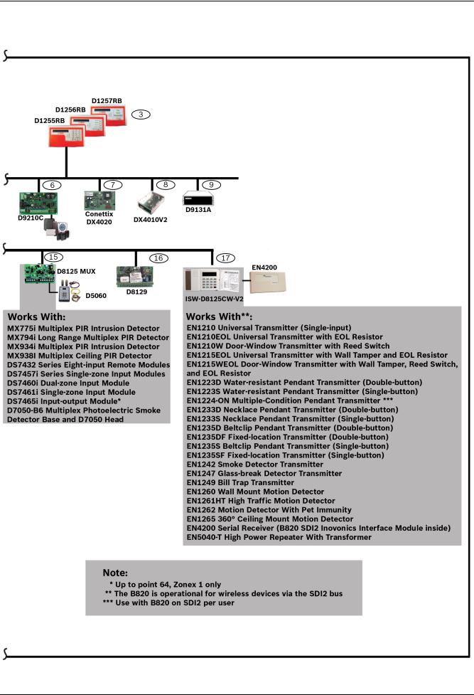
1 GV4 Control Panel Connections (D9412GV4 Shown)
Pages 5 and 6 describe the GV4 Series configuration and supported devices.
Bosch Security Systems, Inc. |
Quick Reference Guide |
F01U215242 | 01 | 2011.10 |
6 |
en | GV4 Control Panel Connections (D9412GV4 Shown) |
D9412GV4/D7412GV4/D7212GV4 |
|
|
|
F01U215242 | 01 | 2011.10 |
Quick Reference Guide |
Bosch Security Systems, Inc. |
D9412GV4/D7412GV4/D7212GV4 Upgrade GV4 Hardware and Programming | en 7
2 |
Upgrade GV4 Hardware and Programming |
|||
2.1 |
Receive Existing Control Panel Programming |
|||
|
|
|
|
|
|
NOTICE! |
|||
|
GV4 Series control panels are not compatible with the D5200 Programmer. |
|||
|
|
|
|
|
2.1.1 |
Receive Existing Control Panel Programming with RPS |
|||
|
1. |
In RPS, double-click on the control panel name. |
||
|
2. |
Click Connect. Once connected, the Panel Sync window opens. |
||
|
3. |
Select the Recieve Panel Data option button and click OK. |
||
2.2 |
Upgrade Hardware to a GV4 Series Control Panel |
|||
2.2.1 |
Prepare to Remove Existing Hardware |
|||
|
1. |
Power down the existing control panel by disconnecting the battery and the AC power. |
||
|
2. |
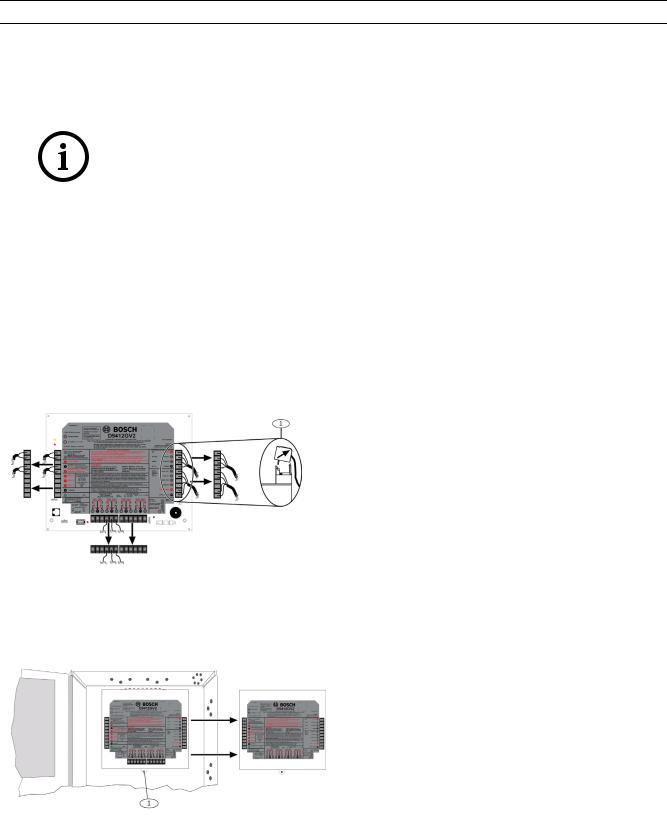
Remove the four removable terminal strips by tilting the strip up and outward. |
||
|
|
Do not remove the wiring from the terminal strip. |
||
|
|
|
|
|
|
|
|
1 - Removable terminal strips |
|
|
|
|
|
|
2.2.2 |
Remove the Existing Control Panel |
||
|
1. |
Remove the lock down tab screw. |
|
|
2. |
Lift up on the control panel to free it from the enclosure mounting hooks, and remove the |
|
|
|
control panel from the enclosure it. |
|
|
|
|
|
|
|
|
1 - Lock down tab |
|
|
|
|
|
|
|
|
Bosch Security Systems, Inc. |
Quick Reference Guide |
F01U215242 | 01 | 2011.10 |
8 en | Upgrade GV4 Hardware and Programming D9412GV4/D7412GV4/D7212GV4
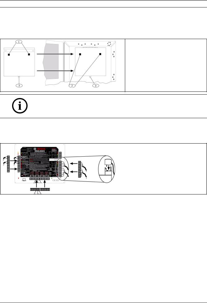
2.2.3 Install the GV4 Control Panel In the Enclosure
1.Place the GV4 Control Panel in the enclosure using the mounting skirt hook holes on the back of the control panel and the mounting skirt hooks on the enclosure.
2.Replace the lock down tab screw.
1 - Mounting skirt hook holes
2 - Mounting skirt hooks
3 - Lock down tab
NOTICE!
If the control panel was previously mounted using the screw hole configuration, the you must re-mount the new control panel. The GV4 control panel mounting screw hole locations do not align with the locations for older control panels.
2.2.4 Replace the Terminal Strips
1. Replace the removable terminal strips by pushing them straight down until they snap into position.
2.Connect the battery and AC power.
F01U215242 | 01 | 2011.10 |
Quick Reference Guide |
Bosch Security Systems, Inc. |

D9412GV4/D7412GV4/D7212GV4 Upgrade GV4 Hardware and Programming | en 9
2.3 |
Upgrade Programming to a GV4 Control Panel Programming |
|
|
|
|
|
NOTICE! |
|
|
You must upgrade G Series and Non-G Series control panels to GV2 programming prior to |
|
|
upgrading to GV4 programming. |
|
|
|
|
2.3.1 |
Upgrade a GV3 Series, GV2 Series, G Series, or Non-G Series Control Panel |
|
|
to a GV4 or Later Using Remote Programming Software (RPS) 5.14 or Later |
|
|
RPS version 5.14 or newer is required to upgrade an existing G Series, GV2, or GV3 Series |
|
|
Control Panel installation to a GV4 Series Control Panel. Refer to the RPS help files for the |
|
|
specific control panel for additional information on control panel conversion. |
|
|
1. |
In RPS, highlight the control panel name by selecting it. |
|
2. |
Click the View button on the Remote Programmer Toolbar. |
|
3. |
In the resulting Panel Data - View window, click the Edit button. |
|
4. |
In the resulting Panel Data - Edit window, select the new control panel type from the |
|
|
Panel Type drop-down. (If the control panel is a G or Non-G Series control panel, you |
|
|
must upgrade to GV2 first, followed by GV3, and then repeat each of these steps to |
|
|
choose the GV4 control panel). |
|
5. |
Click OK to close window. |
|
6. |
Click Save in the Panel View window to save the changes and close the Panel View |
|
|
window. |
|
7. |
Click Connect. Once connected, the Panel Sync window opens. |
|
8. |
Select the Send ALL RPS Data to Panel option button and click OK. |
|
9. |
Once the sync completes, click Disconnect to disconnect from the control panel. |
|
10. |
Exit RPS. |
|
11. |
Test the control panel for operation. |
Bosch Security Systems, Inc. |
Quick Reference Guide |
F01U215242 | 01 | 2011.10 |

10 en | Programming the Control Panel D9412GV4/D7412GV4/D7212GV4
3 |
Programming the Control Panel |
|
You can program the control panel with RPS using a network connection or serial connection. |
|
You can program some paramaters of the control panel with keypad programming. |
3.1 |
RPS Programming over a Network Using the DX4020 Ethernet |
|
Network Interface Module |
|
For additional information, refer to IP Address Programming in the Conettix DX4020 Network |
|
Interface Module Installation Guide (P/N: F01U045288). |
3.2 |
RPS Programming over a Network Using the ITS-DX4020-G |
|
GPRS/GSM Communicator |
|
For additional information, refer to the Conettix ITS-DX4020-G Installation Guide (P/ |
|
N: F01U163066). |
3.3 |
RPS Programming Using the DX4010V2 RS-232/USB Serial |
|
Interface Module |
|
For additional information, refer to the DX4020 RS-232/USB Serial Interface Module Installation |
|
Instructions (P/N: F01U083036). |
3.4 |
RPS Programming Using the B420 Ethernet Communication |
|
Module |
|
For additional information, refer to Programming Through a Control Panel in the B420 Ethernet |
|
Communication Module Installation and Operation Guide (P/N: F01U215236). |
3.5 |
Programming Using the Keypad Tools Menu |
|
For additional information, refer to the GV4 Series Program Entry Guide (P/N: F01U218312). |
F01U215242 | 01 | 2011.10 |
Quick Reference Guide |
Bosch Security Systems, Inc. |
Loading...