


BC2680RA
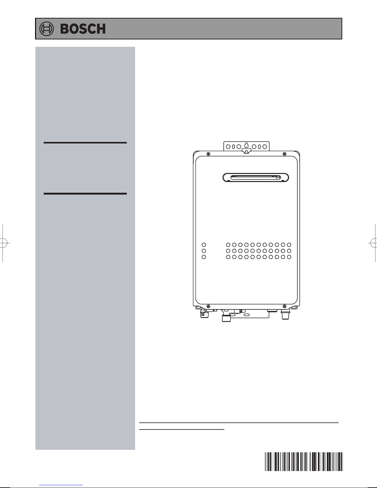
Installation Manual
External Models
BC2680RA
BC2680RA5
BC2180RA
BC2180RA5
Installation Instructions
To be installed and serviced only
by an authorised person
This appliance is not suitable for
use as a pool heater
The "authorised installing person" is
responsible for:
1. Correct commissioning of this
appliance.
2. Ensure unit performs to the
specifications stated on the
rating label.
3. Demonstrate operation of unit to
customer before leaving.
Hand these instructions to
4.
customer
AU Service Department: 1300 30 70 37
NZ Service Department: 0800 54 33 52
.
This appliance must be installed in accordance with the manufacturer's
installation instructions, AS/NZS5601, AS/NZS3500.4, AS3000 wiring
regulations and all Local Building, Water and Gas fitting regulations.
Failure to install this appliance in accordance with these installation
instructions may void warranty
In the interest of continued product improvement, Bosch reserves the
right to alter these specifications
without notice.
SBB808C
Rev. 10/14
*SBB808C*

Contents
1. Included Accessories ............................................................................. 4
2. Optional Accessories ............................................................................. 4
3. Dimensions ............................................................................................. 5
4. Component Details ................................................................................. 6
5. Before Installation .................................................................................. 7
6. Specifications ......................................................................................... 8
7. Choosing Installation Site...................................................................... 9
Installation Instructions
8. Installation Clearances.......................................................................... 10
9. Installation .............................................................................................. 12
10. Gas Piping .............................................................................................. 13
11. Water Piping ........................................................................................... 14
12. Condensate Piping ................................................................................ 16
13. Electrical Wiring..................................................................................... 17
14. Maintenance ........................................................................................... 20
15. Trial Operation ....................................................................................... 20
WATER QUALITY ......................................................................................... 22
2

Installation Instructions
Robert Bosch
Installation Manual
(Australia) Pty. Ltd.
CONDENSING GAS WATER HEATER
BC2680RA BC2680RA5
(Outdoor Installation)
BC2180RA BC2180RA5
Potential dangers from accidents during installation and use are divided into the following three
categories. Closely observe these warnings, they are critical to your safety.
DANGER indicates an imminently hazardous situation which,
DANGER
WARNING
CAUTION
WARNING: If the information in this manual is not followed exactly, a fire or explosion may result
causing property damage, personal injury or death.
Prohibited
if not avoided, will result in death or serious injury.
WARNING indicates a potentially hazardous situation which,
if not avoided, could result in death or serious injury.
CAUTION indicates a potentially hazardous situation which,
if not avoided, may result in minor or moderate injury.
Disconnect
Power
Earth
Be sure to do
Requests to Installers
• In order to use the water heater safely, read this installation manual carefully, and follow the
installation instructions.
• Failures and damage caused by erroneous work or work not as instructed in this manual are not
covered by the warranty.
• Check that the installation was done properly in accordance with this Installation Manual upon
completion.
•
After completing installation, please either place this Installation Manual in a plastic pouch and
attach it to the side of the water heater,
• The water heater must be commissioned including checking gas supply pressures at maximum
demand.
•
The operation of the water heater should be explained including normal operation & regular
maintenance.
CAUTION
or hand it to the customer to retain for future reference.
CAUTION
3
Installation Instructions
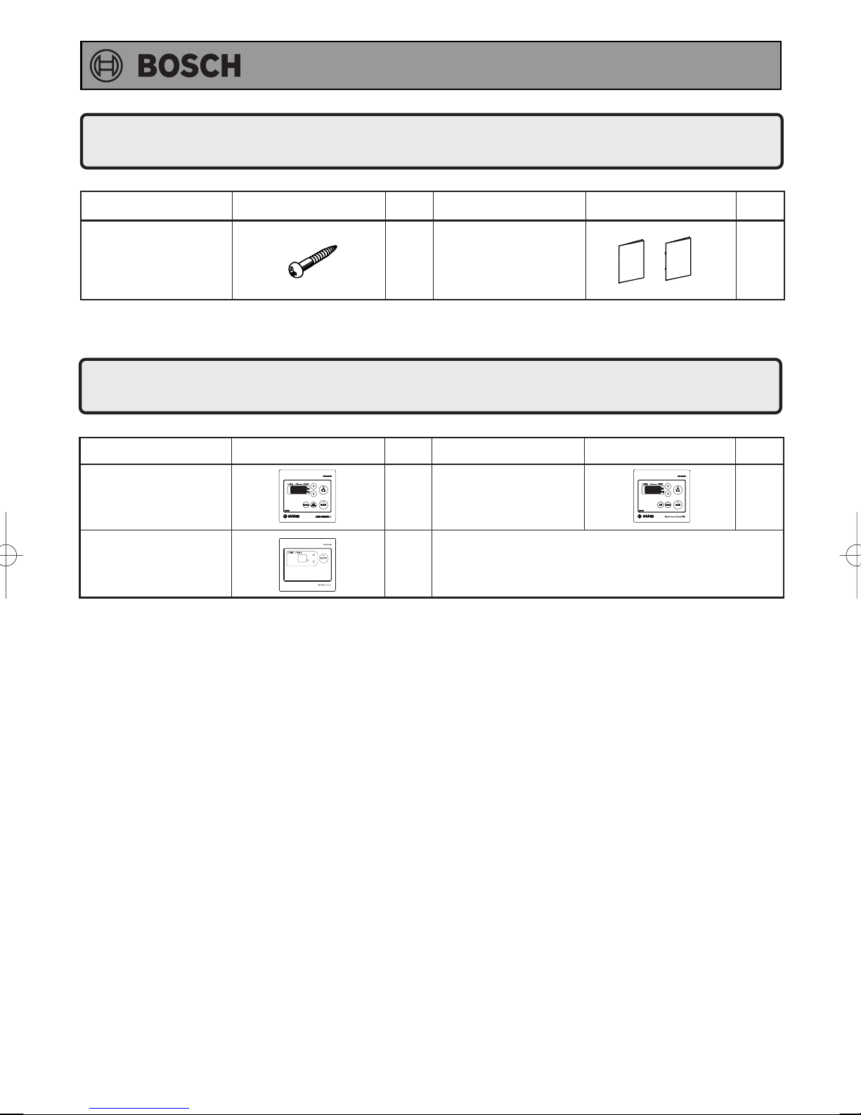
1.
Included Accessories
The following accessories are included with the unit.
Check for any missing items before starting installation.
Part Shape Q’ty
Anchoring Screw
2.
Optional Accessories
Main Controller
(YPRM67XBN)
Sub Controller
(YPRP62XBN)
Owner's Guide,
Installation Manual
5
(this document)
The accessories listed below are not
included with the units, but may be necessary
for installation.
Bathroom Controller
1
1
(YPRS67XBN)
Q’tyShapePart
1
each
Q’tyShapePartPart Shape Q’ty
1
• Maximum two Sub controllers can be used. See P.18 for details.
4

Dimensions
(
)
)
3.
×
13 OBLONG HOLE
6
120
85
50
1010
Installation Instructions
10
170
40
27
11
338
350
334
217
<Unit : mm>
28
5628
542
60
90
120
HEIGHT OF EACH FITTING
FROM BOTTOM OF CASE
HOT WATER OUTLET
COLD WATER INLET
GAS INLET
CONDENSATE DRAIN
487 31
AIR INLET
10
45
58
50
30
133
WATER DRAIN VALVE
HOT WATER OUTLET
WATER DRAIN VALVE
CONDENSATE DRAIN
520
(VIEW FROM TOP)
102
96
30
AIR INLET
COLD WATER INLET
WIRING THROUGHWA Y
GAS INLET
WATER DRAIN VALVE
(WATER FILTER)
296
252
CONDENSATE DRAIN(R1/2
GAS INLET(R3/4)
21
45
87
HOT WATER OUTLET(R3/4)
COLD WATER INLET
R3/4
97
40
WIRING THROUGHWA Y
5

Installation Instructions
Component Details
4.
• BC2680RA series, BC2180RA series
Secondary heat exchanger
Flue collar
High limit switch
Water level electrode
Neutraizer
Anti-frost heater
Igniter
Freeze protection thermostat
Main flow control valve
Water outlet thermistor
Anti-frost heater
Water drain valve
Primary heat exchanger
Anti-frost heater
Thermal fuse
Flame rod
Ignition plug
Burner manifold & gas valve
Circuit board
Water inlet thermistor
Water flow sensor
Fan motor
Hot water outlet
Drain outlet
Cold water inlet
6
Gas inlet
Power code
Water drain valve
Installation Instructions
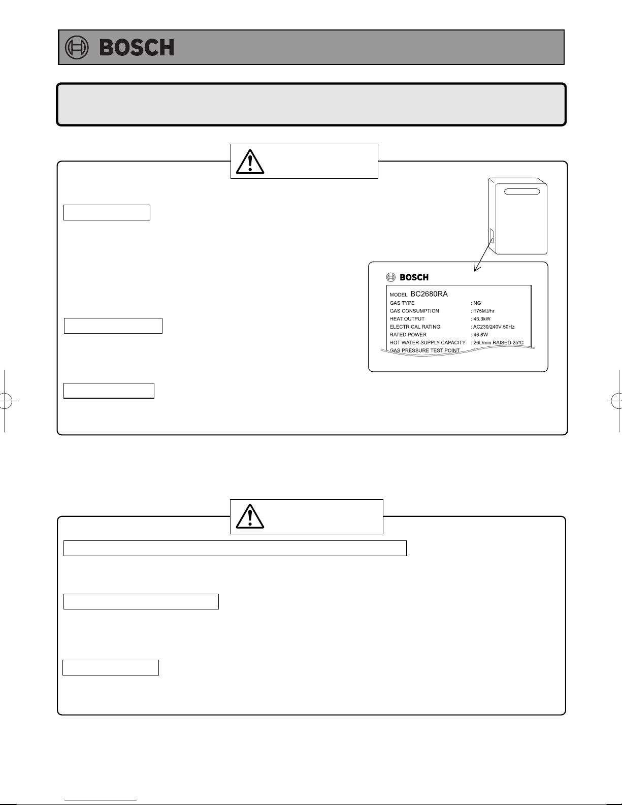
Before Installation
5.
WARNING
Check the Gas
• Check that the data plate (located inside of front cover) or
a temporary label (located on the front cover)
indicates the correct type of gas.
• Check that the gas supply line is sized for
BC2680RA(5): NG 175 MJ/hr, LP 185 MJ/hr
BC2180RA(5): NG 145 MJ/hr, LP 149 MJ/hr for this unit.
•
DO NOT OPERATE WITH ANY OTHER GAS TYPE.
Check the Power
• The power supply required is 230/240VAC, at 50Hz.
Using the incorrect voltage may result in fire or
electric shock.
For NG Gas
Warning labels
• Located on the left side of the casing -PLEASE READ THESE LABELS CAREFULLY!
CAUTION
Do Not Use Equipment for Purposes Other Than Those Specified
• Do not use for other than increasing the temperature of the water supply, as unexpected accidents
may occur as a result.
Check Water Supply Quality
• If the water supply is hard, acidic or otherwise impure, treat the water with approved methods in
order to ensure full warranty coverage.
See water quality statement on page 22.
Frost Protection
•
When installed, power to the unit must be kept switched on, otherwise the appliance should be drained.
This prevents water freezing, and causing damage to the water heater.
7
 Loading...