


ASWP-2475C-FR
Copyright 2005 Wheelock, Inc. All rights reserved. P83957N
Sheet 1 of 4
273 Branchport Avenue
Long Branch, NJ 07740 Thank you for using our products.
(800) 631-2148 (USA)
INSTALLATION INSTRUCTIONS
(800) 397-5777 (CANADA)
SERIES ASWP AUDIBLE STROBE WEATHERPROOF APPLIANCE
www.wheelockinc.com
(WALL/CEILING MOUNT VERSION)
Use this product according to this instruction manual. Please keep this instruction manual for future reference.
GENERAL:
Wheelock’s Series ASWP appliance is the industry’s first 2-wire horn strobe alarm appliance that provides a selectable continuous or Code 3 horn tone and continuous
strobe when connected directly to the Fire Alarm Control Panel (FACP), or provides a synchronized Code 3 horn tone and synchronized strobe when used in
conjunction with a Sync Module (SM), Dual Sync Module (DSM) or Wheelock power supplies. The ASWP appliance is UL Listed for indoor/outdoor use under
Standard 1638 for Emergency Devices for the Hearing Impaired (Visual Signal Appliances) and UL Standard 464 for Audible Signal appliances. The ASWP is also
ULC Listed under Standard CAN/ULC-S526-02 for Visual Signaling Appliances and Standard CAN/ULC-S525-99 for Audible Signaling Appliances. The strobe has
an intensity of 75 candela on axis at -35°C and low current draw. For outdoor application the ASWP must be mounted to the Weatherproof Backbox (WPBB). The
ASWP uses a xenon flashtube with solid state circuitry enclosed in a polycarbonate lens to provide maximum visibility and reliability for effective visible signaling.
The ASWP appliance can be field set to provide either high (HI) dBA, medium (MED) dBA or low (LO) dBA sound output.
The strobe is designed for use with either filtered DC (VDC) or unfiltered full-wave-rectified (FWR) input voltage. All inputs are polarized for compatibility with
standard reverse polarity supervision of circuit wiring by a FACP.
NOTE: The Code 3 temporal pattern (1/2 second on, 1/2 second off, 1/2 second on, 1/2 second off, 1/2 second on, 1-1/2 off and repeat) is specified by ANSI and
NFPA 72 for standard emergency evacuation signaling. The Code 3 Horn should be used only for fire evacuation signaling and not for any other purpose.
NOTE: All Canadian Installations should be in accordance with the Canadian Standard for the Installation of Fire Alarm Systems - CAN/ULC-S524-01 and Canadian
Electrical Code, Part 1. Final acceptance is subject to authorities having jurisdiction (AHJ).
WARNING: PLEASE READ THESE INSTRUCTIONS CAREFULLY BEFORE USING THIS PRODUCT. FAILURE TO COMPLY WITH ANY OF
THE FOLLOWING INSTRUCTIONS, CAUTIONS AND WARNINGS COULD RESULT IN IMPROPER APPLICATION, INSTALLATION AND/OR
OPERATION OF THESE PRODUCTS IN AN EMERGENCY SITUATION, WHICH COULD RESULT IN PROPERTY DAMAGE AND SERIOUS
INJURY OR DEATH TO YOU AND/OR OTHERS.
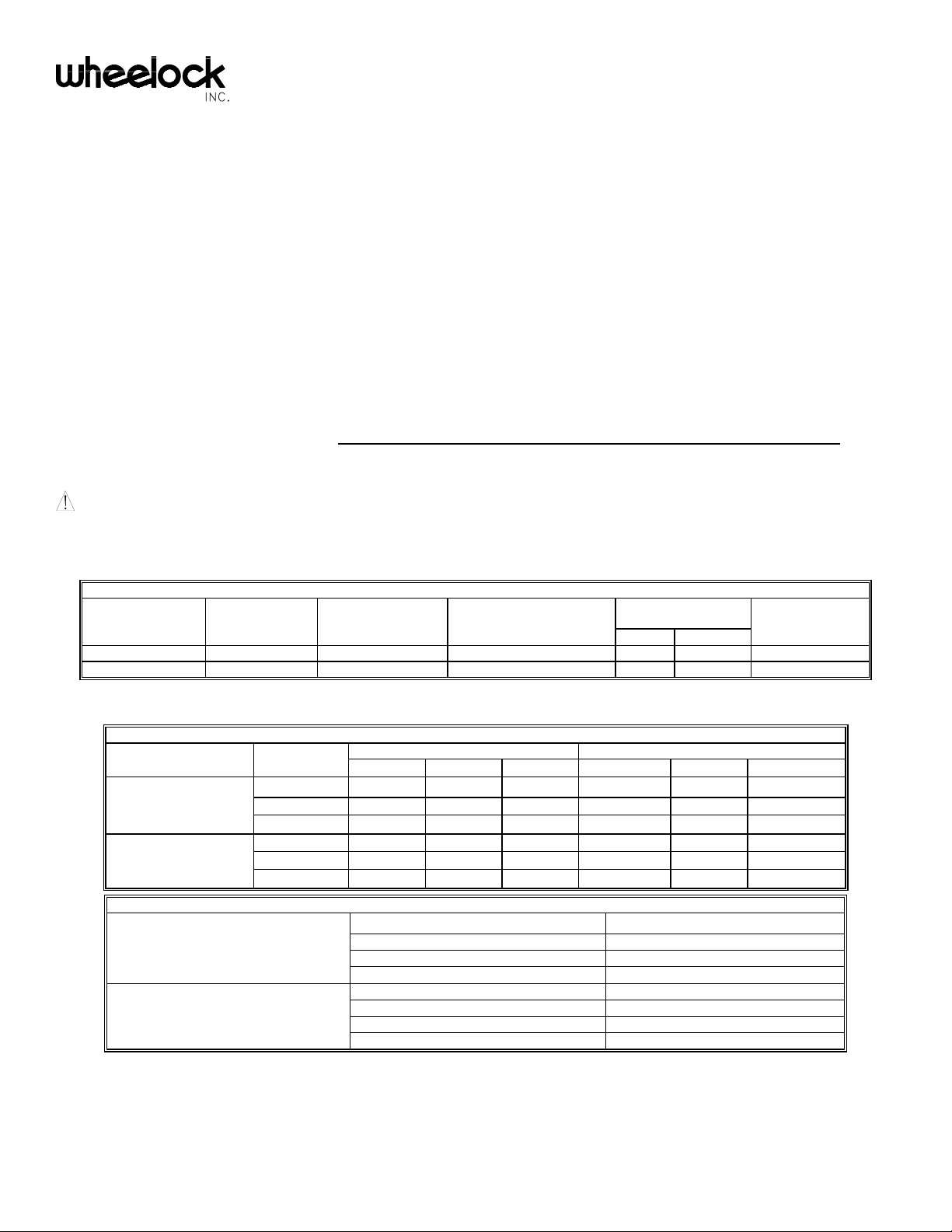
SPECIFICATIONS:
Table 1: UL/ULC Ratings
UL Rated
Light Output at
Model
Regulated
Voltage
(VDC/VRMS)
Voltage Range Limit
Per UL 1638/464
(VDC/VRMS)
Voltage Range Per
CAN/ULC-S525-99/S526-02
(VDC/VRMS)
+25°C -35°C
ULC Rated
Light Output
ASWP-2475W 24 16.0-33.0 20.0-31.0 180cd 75cd 30cd
ASWP-2475C 24 16.0-33.0 20.0-31.0 180cd 75cd 30cd
ASWP-2475W is for wall applications. ASWP-2475C is for ceiling.
Table 2: UL/ULC dBA Sound Output
Description Volume Reverberant Per UL 464 Anechoic dBA Per CAN/ULC-S525-99
16.0VDC 24.0VDC 33.0VDC 20.0VDC 24.0VDC 31.0VDC
Low 80 83 86 88 90 91
Continuous Horn Medium 85 88 91 93 95 97
High 88 91 93 97 99 100
Low 75 79 82 88 90 91
Code 3 Horn Medium 80 84 86 93 95 97
High 84 87 90 97 99 100
Table 2A: ULC - Directional Characteristics per CAN/ULC-S526-02
Angle (Reference 90°)
OSPL - 101dB
136°
98dB
145°
95dB
Horizontal Axis
180°
90dB
Angle (Reference 90°)
OSPL - 102dB
113°
99dB
120°
96dB
Vertical Axis
180°
91dB
P83957 N
Sheet 2 of 4
NOTES:
1. Strobe will produce 1 flash per second over the "Regulated Voltage" range.
2. These models meet the required light distribution patterns defined in UL 1638 and ULC S526-02.
3. All models are UL/ULC Listed for indoor and outdoor use with a temperature range of -31°F to 150°F (-35°C to +66°C) and maximum humidity of 98%, ± 2% RH.
The effect of shipping and storage temperatures shall not adversely affect the performance of the appliance when it is stored in the original cartons and is not
subjected to misuse or abuse.
CAUTION: Strobes are not designed to be used on coded systems in which the applied voltage is cycled on and off.
When calculating the total current: Use Table 3 to determine the highest value of “RMS Current” for an individual AS Appliance then multiply the value by the total
number of AS Appliances. Be sure to add the currents for any other appliances powered by the same source and include any required safety factors.
NOTE: The maximum number of strobes on a single notification appliance circuit shall not exceed 50.
Table 3: Current Ratings (AMPS)
Maximum RMS Current with Hi dBA Setting
Voltage
DC 16.0-33.0VDC 0.168
FWR 16.0-33.0VRMS 0.235
Maximum RMS Current with Med dBA Setting
Voltage
DC 16.0-33.0VDC 0.155
FWR 16.0-33.0VRMS 0.225
Maximum RMS Current with Low dBA Setting
Voltage
DC 16.0-33.0VDC 0.150
FWR 16.0-33.0VRMS 0.220
CAUTION: These notification appliances are UL Listed as “Regulated”. They are intended to be used with FACPs whose notification circuits are UL Listed as
“Regulated.” These appliances shall not be used on UL Listed “Special Application” notification circuits unless the appliances are identified to be compatible in the
installation instructions of the FACP or unless the FACP is identified to be compatible in this instruction manual.
WARNING: THESE APPLIANCES WERE TESTED TO THE REGULATED VOLTAGE LIMITS OF 16.0-33.0 VOLTS FOR 24V MODELS USING
FILTERED DC OR UNFILTERED FULL-WAVE-RECTIFIED VOLTAGE. DO NOT APPLY VOLTAGE OUTSIDE OF THIS RANGE.
WARNING: CHECK THE MINIMUM AND MAXIMUM OUTPUT OF THE POWER SUPPLY AND STANDBY BATTERY AND SUBTRACT THE
VOLTAGE DROP FROM THE CIRCUIT WIRING RESISTANCE TO DETERMINE THE APPPLIED VOLTAGE TO THE STROBES. THE MAXIMUM
WIRE IMPEDANCE BETWEEN STROBES SHALL NOT EXCEED 35 OHMS.
WARNING: MAKE SURE THAT THE TOTAL RMS CURRENT REQUIRED BY ALL APPLIANCES THAT ARE CONNECTED TO THE
SYSTEM’S PRIMARY AND SECONDARY POWER SOURCES, NOTIFICATION APPLICIANCE CIRCUITS, SM, DSM SYNC MODULES, OR
WHEELOCK POWER SUPPLIES DOES NOT EXCEED THE POWER SOURCES’ RATED CAPACITY OR THE CURRENT RATINGS OF ANY FUSES
ON THE CIRCUITS TO WHICH THESE APPLIANCES ARE WIRED. OVERLOADING POWER SOURCES OR EXCEEDING FUSE RATINGS
COULD RESULT IN LOSS OF POWER AND FAILURE TO ALERT OCCUPANTS DURING AN EMERGENCY, WHICH COULD RESULT IN
PROPERTY DAMAGE AND SERIOUS INJURY OR DEATH TO YOU AND/OR OTHERS.
SOUND OUTPUT (SPL) SETTINGS:
WARNING: THE AUDIBLE STROBE APPLIANCES MUST BE FIELD SET TO THE DESIRED TONE AND dBA SOUND OUTPUT LEVEL
BEFORE THEY ARE INSTALLED. THIS IS DONE BY PROPERLY INSERTING JUMPER PLUGS IN ACCORDANCE WITH THESE
INSTRUCTIONS. INCORRECT SETTINGS WILL RESULT IN IMPROPER PERFORMANCE, WHICH COULD RESULT IN PROPERTY DAMAGE
AND SERIOUS INJURY OR DEATH TO YOU AND/OR OTHERS.
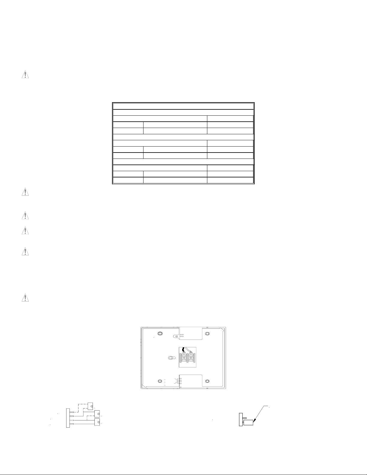
Figure 1: Showing Location of Jumper Plug
CODE 3
HI
MED
LO
Factory setting is on medium dB and Code 3.
Figure 2: Jumper plug settings for High, Medium, Low and Code 3 Figure 3: Jumper plug setting for Continuous Horn
SHOWN SET ON HIGH dB
SHOWN SET ON MED dB
SHOWN SET ON LOW dB
HI
MED
LOW
(Use needle nose pliers to pull and properly set the jumper plugs)
CODE 3
TURN PLUG 90°
No jumper plug is needed for continuous horn setting.
However, it is recommended that the jumper plug be retained in
the unit for future use (if needed) as shown in Figure 4.
 Loading...