


AVENAR FAP-425
AVENAR detector 4000
FAP-425 / FAH-425
en Operation Guide


Table of contents
1
Product Description 4
2
System Overview 5
2.1 Functional Description of the Sensor Technology 5
2.1.1 Optical Sensor (Smoke Detector) 5
2.1.2 Thermal Sensor (Heat Detector) 5
2.1.3 Chemical Sensor (Gas Sensor) 6
2.2 System Description 6
2.3 Flash Frequency and Error Detection 6
2.4 Features 6
2.5 Accessories 7
2.5.1 Remote Indicators 9
3
Planning 13
3.1 Basic Installation/Configuration Notes 13
3.2 Use in a Local Security Network (LSN/LSN improved version) 13
4
Programming 14
4.1 FAP-425-DOTC-R 14
4.2 FAP‑425‑DOT‑R / FAP‑425‑OT‑R / FAP‑425‑OT 15
4.3 FAP‑425‑DO‑R / FAP‑425‑O‑R / FAP‑425‑O 16
4.4 FAH‑425‑T‑R 17
5
Connection 19
5.1 Overview of Detector Bases 19
5.2 Installing the Base 20
5.3 Connection 21
5.3.1 Connecting the MS 400/MS 400 B 22
5.3.2 Connecting the FAA‑MSR 420 22
5.4 Detector Base Sounders 23
5.5 Installation of the Detector Module 24
5.6 Detector Removal 25
5.7 Address Setting 25
6
Order Information 27
6.1 Detector Variants 27
6.2 Detector Bases 27
6.3 Detector Accessories 27
6.4 Installation Accessories 28
6.5 Detector Base Sounders 28
6.6 Service accessories 28
7
Maintenance and Service 30
7.1 Detector Type Encoding 30
7.2 Test Instructions for LSN improved version Fire Detectors 31
7.2.1 Test Instructions for All Fire Detectors With Optical Sensor 31
7.2.2 Test Instructions for FAP‑425‑DOTC‑R / FAP‑425‑DOT‑R / FAP‑425‑OT‑R / FAP‑425‑OT 32
7.3 Diagnostic Data 32
7.4 Warranty 34
7.5 Repair 34
7.6 Disposal 34
8
Technical Data 35
AVENAR detector 4000 Table of Contents | en 3
Bosch Sicherheitssysteme GmbH Operation Guide 2014.11 | 1.1 | F.01U.283.550

Product Description
AVENAR detector 4000 combines standard detection procedures such as scattered light and
temperature measurement with gas measuring technology at the highest configuration level.
This method uses intelligent evaluation electronics (Intelligent Signal Processing - ISP) to
evaluate the signals from the smoke, thermal and gas sensor. Thus, immunity against false
alarms is increased significantly and detection time is reduced in comparison to the fire
detectors available on the market today.
Thanks to the combined information collected by the multi-sensor detectors, they can be used
in environments where simple smoke detectors cannot be employed.
AVENAR detector 4000 is suitable for surface and flush mounting and includes separate
mounting points for dropped ceiling and concealed sockets.
AVENAR detector 4000 is available in different versions of single-sensor and multi-sensor
detectors.
Identifier
Description Material no. Category
FAP-425-O-R Optical smoke detector,
automatic and manual address
setting
F.01U.280.244 Single sensor
FAP-425-OT-R Combined optical and thermal
smoke detector, automatic and
manual address setting
F.01U.280.245 Multi-sensor
FAP-425-O Optical smoke detector,
automatic address setting only
F.01U.279.893 Single sensor
FAP-425-OT Combined optical and thermal
smoke detector, automatic
address setting only
F.01U.279.987 Multi-sensor
FAH-425-T-R Thermal detector, automatic and
manual address setting
F.01U.280.243 Single sensor
FAP-425-DO-R Dual-optical smoke detector,
automatic and manual address
setting
F.01U.279.988 Double sensor
FAP-425-DOT-R Combined dual-optical and
thermal smoke detector,
automatic and manual address
setting
F.01U.279.989 Multi-sensor
FAP-425-DOTC-R Combined dual-optical, thermal
and chemical smoke detector,
automatic and manual address
setting
F.01U.280.451 Multi-sensor
1
4 en | Product Description AVENAR detector 4000
2014.11 | 1.1 | F.01U.283.550 Operation Guide Bosch Sicherheitssysteme GmbH
System Overview
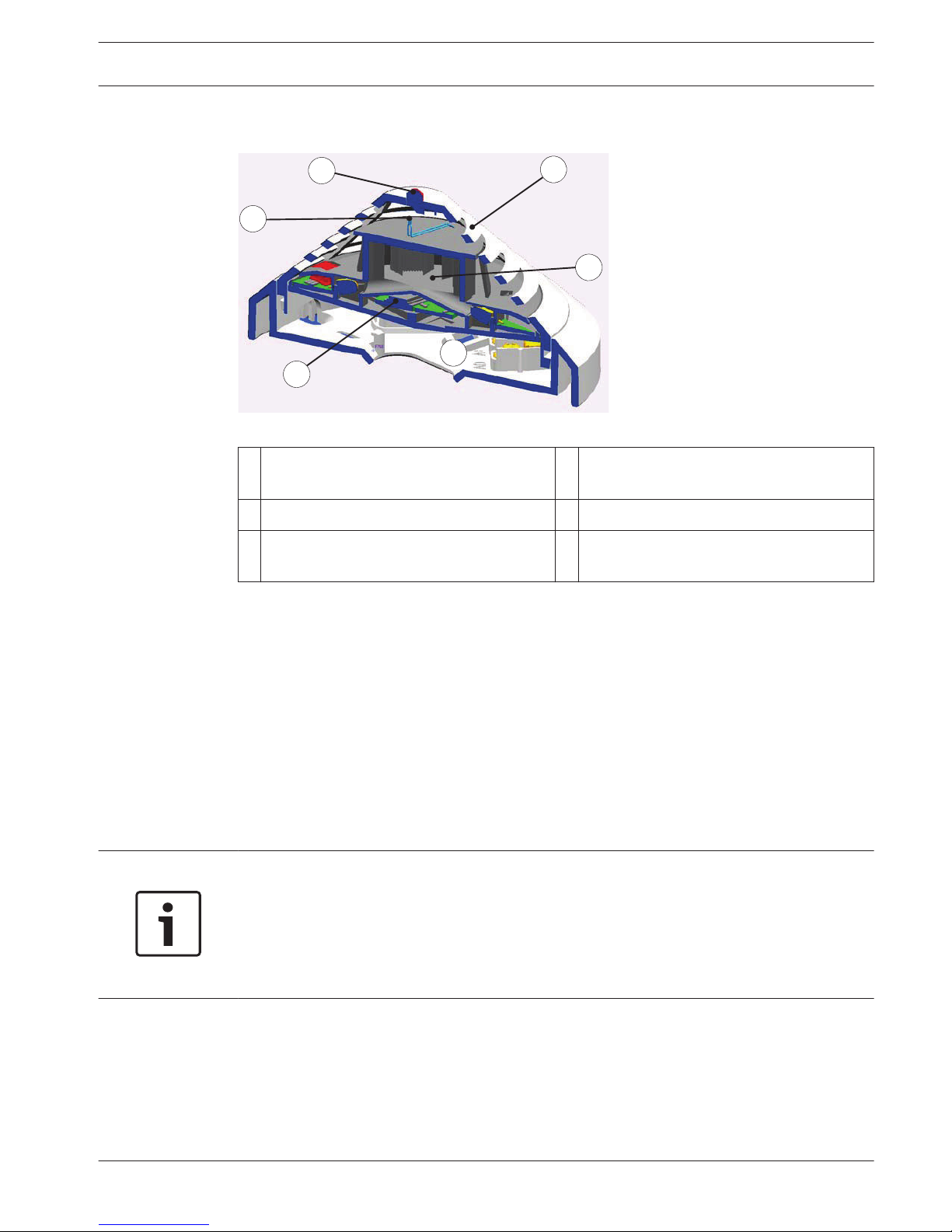
6
4
5
2
1
3
Figure 2.1: Detector set-up
1
Smoke measurement chamber with
optical sensor
4 Individual display
2 Thermal sensor 5 PC board with evaluation electronics
3 Chemical sensor (covered on the cross-
section)
6 MS 400 / MS 400 B Detector Base
Functional Description of the Sensor Technology
Optical Sensor (Smoke Detector)
This optical sensor utilizes the scattered-light method.
An LED sends light into the measuring chamber, where it is absorbed by the labyrinth
structure. In the event of a fire, smoke enters the measuring chamber. The light is scattered by
the smoke particles and hits the photo diodes, which transform the quantity of light into a
proportional electrical signal.
The DO detectors have a dual optical sensor that uses the different infrared and blue light
wavelengths (Dual Ray technology). This allows fires to be detected early and even the
smallest quantities of smoke (TF1, TF9) to be reliably detected.
Notice!
The FAP-425-DO-R smoke detector makes an alarm decision based on an intelligent
combination of the following criteria:
Amount of smoke density measured
Speed of smoke density increase
Size of smoke particles (as measured by Dual Ray technology)
Thermal Sensor (Heat Detector)
A thermistor in a resistance network is used as a thermal sensor; an analog-digital converter
measures the temperature-dependent voltage at regular intervals.
Depending on the specified detector class, the thermal sensor triggers the alarm status when
the maximum temperature of 54 °C or 69 °C is exceeded (thermal maximum), or if the
temperature rises by a defined amount within a specified time (thermal differential).
2
2.1
2.1.1
2.1.2
AVENAR detector 4000 System Overview | en 5
Bosch Sicherheitssysteme GmbH Operation Guide 2014.11 | 1.1 | F.01U.283.550
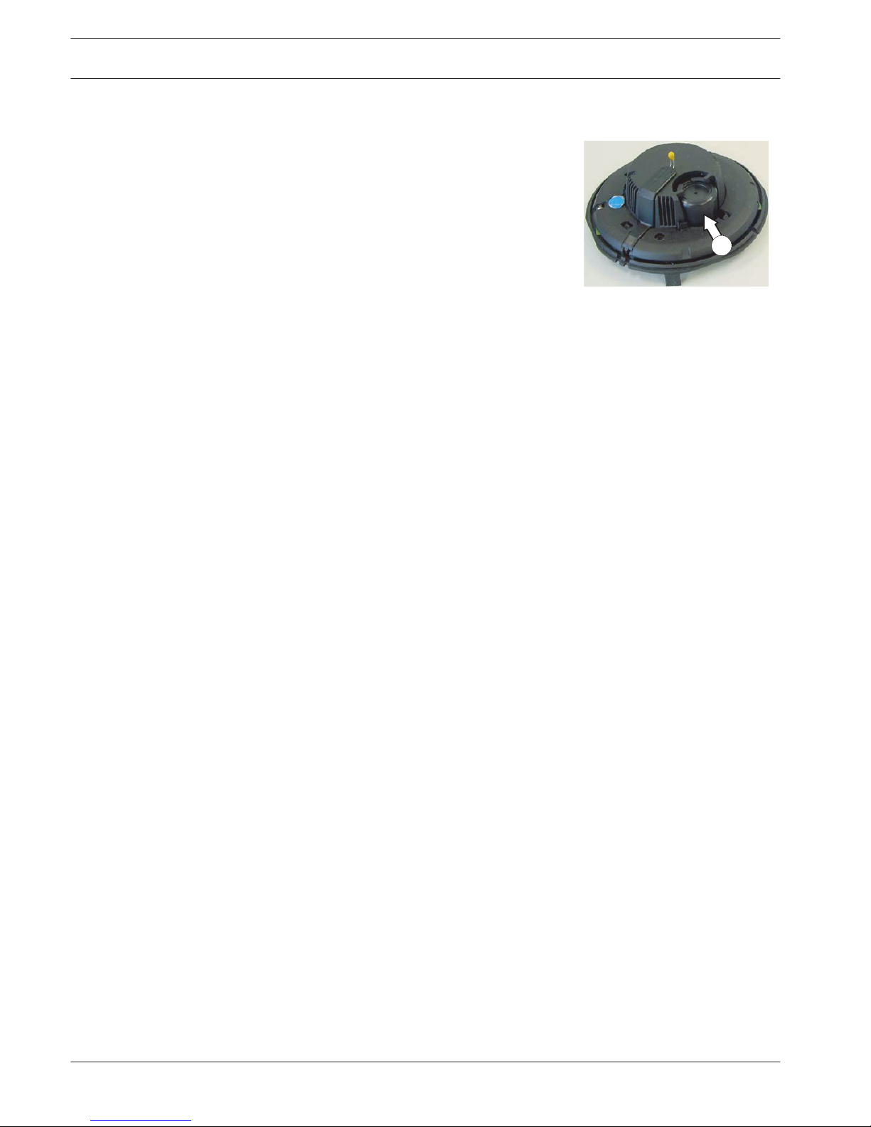
Chemical Sensor (Gas Sensor)
The gas sensor detects mainly the carbon monoxide (CO)
that is produced by a fire, but it also detects hydrogen (H)
and nitrogen monoxide (NO).
The underlying measurement principle is CO oxidation and
the measurable current that it creates. The sensor signal
value is proportional to the concentration of gas.
The gas sensor supplies additional information in order to
reliably suppress disturbance variables.
3
Chemical sensor
System Description
Up to three detection principles are integrated in FAP-425/FAH-425 series detectors:
– Optical (for smoke): O
– Dual-optical (for smoke): DO
– Thermal (for heat): T
– Chemical (for CO gas): C
– Detector with rotary switch: R, automatic and manual addressing
The individual sensors are programmed via the LSN network manually or using a timer. All
sensor signals are analyzed continually by the internal signal analysis electronics (ISP) and are
linked with each other. By linking the sensors (combined detectors), the detector can also be
used in places where the work carried out gives rise to light smoke, steam or dust. If a signal
combination fits the selected identifier for the area of operation for the detectors, an alarm is
triggered automatically.
Flash Frequency and Error Detection
The LSN improved detector has two centrally positioned two-color LEDs that flash green to
display the operational status.
The green LED on LSN improved FAP-425/FAH-425 series detectors is deactivated when
delivered. It can be activated as required via the programming software.
The LSN improved detector permanently monitors and adjusts itself throughout its life cycle in
order to adapt its sensitivity to the set threshold value.
A message is sent to the fire panel if the detector becomes too contaminated.
The LED will start to flash red as soon as an alarm is triggered.
The detector will return to its normal operating condition when the alarm is canceled via the
control panel or if the alarm cause disappears.
Features
– Active self-monitoring of the sensors, with display on the fire panel:
– Active adjustment of the threshold (drift compensation) if the optical sensor
becomes contaminated.
– Active adjustment of the threshold (drift compensation) of the chemical sensor.
– EMC safety is 50 V/m and is therefore much higher than normatively required.
– Preservation of LSN loop functions in the event of wire break or short-circuit of a detector
through integrated isolators.
– Individual detector identification on the fire panel in the event of an alarm. Alarm
indication on the detector with a flashing red LED.
– Programmable, i.e. can be adjusted to the area of operation.
2.1.3
2.2
2.3
2.4
6 en | System Overview AVENAR detector 4000
2014.11 | 1.1 | F.01U.283.550 Operation Guide Bosch Sicherheitssysteme GmbH
– Increased detection and false alarm security thanks to evaluation of the temporal
behavior of fire and disturbance variables.
– Activation of a remote indicator is possible.
– Optional mechanical removal safeguard (can be activated/deactivated).
– Dust-resistant labyrinth and cap construction.
– Every detector base has a Chamber Maid Plug (a cleaning opening with a plug) for
blowing out the optical chamber with compressed air (not required for the FAH-425-T-R
Heat Detector).
– For connecting to the FPA-5000 and FPA-1200 fire panels with extended range of LSN
features.
– In classic mode, can be connected to the BZ 500 LSN, UEZ 2000 LSN and UGM 2020 LSN
fire panels and to other panels or their receiver modules with identical connection
properties but with the existing LSN system limits.
– It is possible to read out the serial number, contamination level (for the O sensor),
operating hours, EMC strength level and current analog values for each configured
detector via LSN.
– Use of shielded and unshielded cables.
– The LSN improved version line technology supports the connection of up to 254 FAP-425/
FAH-425 series detectors per loop or stub (please observe national regulations in this
regard).
– Flexible network structures without additional elements are possible (T-tapping is not
feasible with detector versions without rotaries).
– Automatic or manual detector addressing selectable.
– Compliant with EN 54, EN 50131 and VdS guidelines.
For DO detectors, note:
Notice!
The device cannot be used with the FPA-5000 type A panel controller.
Accessories
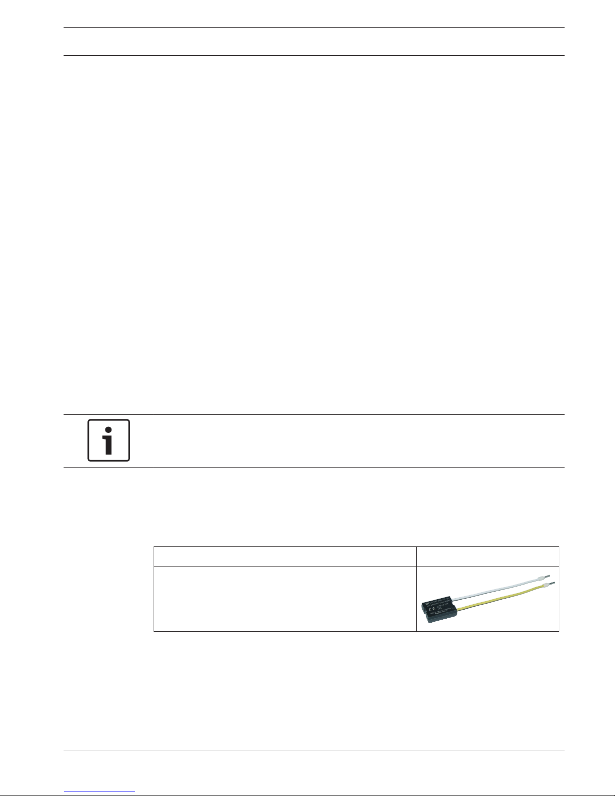
FLM-320-EOL2W EOL Module
FLM-320-EOL2W EOL Module
The FLM-320-EOL2W EOL module is a 2-wire module for
terminating a line according to EN 54-13.
The module detects faults according to EN 54-13 and
reports errors to the fire panel.
Support Plates
The support plates are made from 1.8 mm thick ABS plastic and are clamped between the
detector base and the ceiling.
2.5
AVENAR detector 4000 System Overview | en 7
Bosch Sicherheitssysteme GmbH Operation Guide 2014.11 | 1.1 | F.01U.283.550
TP4 400 Support Plate
The TP4 400 Support Plate is intended for an installation
height up to 4 m and is designed for labels up to a size of
approx. 65 x 34 mm.
15 / 4
TP8 400 Support Plate
The TP8 400 Support Plate is intended for an installation
height up to 8 m and is designed for labels up to a size of
approx. 97 x 44 mm.
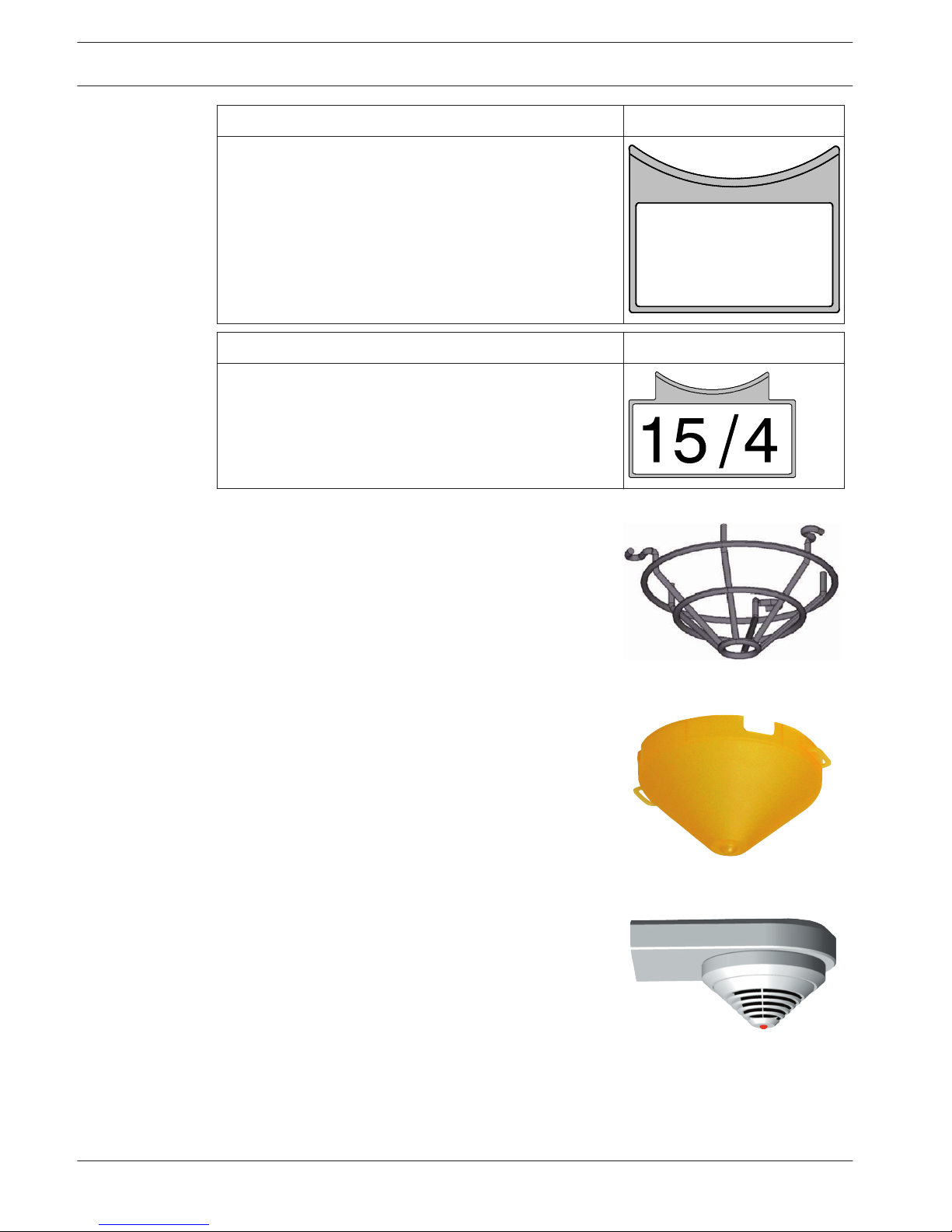
SK 400 Protective Basket
The SK 400 Protective Basket is installed over the detector
and gives the detector substantial protection against
damage.
If the detector is mounted in a sports facility, for example,
the protective basket prevents balls or other sports
equipment from hitting the detector and damaging it.
SSK 400 Protective Dust Cover
The SSK 400 Protective Dust Cover is necessary during
construction work to protect an installed detector base,
with or without detector module, from contamination. The
protective dust cover made of polypropylene (PP) is
pushed onto the installed detector base.
MK 400 Detector Console
The MK 400 Detector Console is used to install detectors
above door frames or similar in compliance with DIBt.
The console is supplied with a pre-mounted MS 400
Detector Base (the detector shown is not included in the
scope of delivery).
8 en | System Overview AVENAR detector 4000
2014.11 | 1.1 | F.01U.283.550 Operation Guide Bosch Sicherheitssysteme GmbH
MH 400 Detector Heating Element
The MH 400 Detector Heating Element is required if the
detector is used in an environment where water
condensation can occur, such as in a warehouse that must
frequently be opened briefly for delivery vehicles.
The detector heating element is connected to the + V/0 V
terminals in the detector base.
Operating voltage: 24 V DC
Resistance: 1 kΩ
Power consumption: 3 W.
The heating is supplied with power either by the fedthrough supply voltage via the central unit or by a separate
power pack.
With supply via the central unit, the number of detector
heating elements depends on the cable diameter and line
length used.
Remote Indicators
A remote indicator is required if the detector is not directly visible or has been mounted in
false ceilings or floors. The remote indicator should be installed in corridors or access
pathways to the corresponding building sections or rooms.
Installation of the FAA-420-RI Remote Indicator
!
Warning!
Malfunction and Damage
If maximum current consumption of the connected detector is larger than 20 mA, it can result
in malfunction and damage to the remote indicator.
Before assembly remove the cap from the base plate
1. Unlock the snap‑fit hook by pressing on it with a flat object and lift the cap carefully
2. Remove the connection board for easy access.
3. Mount the base plate directly on a dry, level surface with two or four screws.
2.5.1
AVENAR detector 4000 System Overview | en 9
Bosch Sicherheitssysteme GmbH Operation Guide 2014.11 | 1.1 | F.01U.283.550
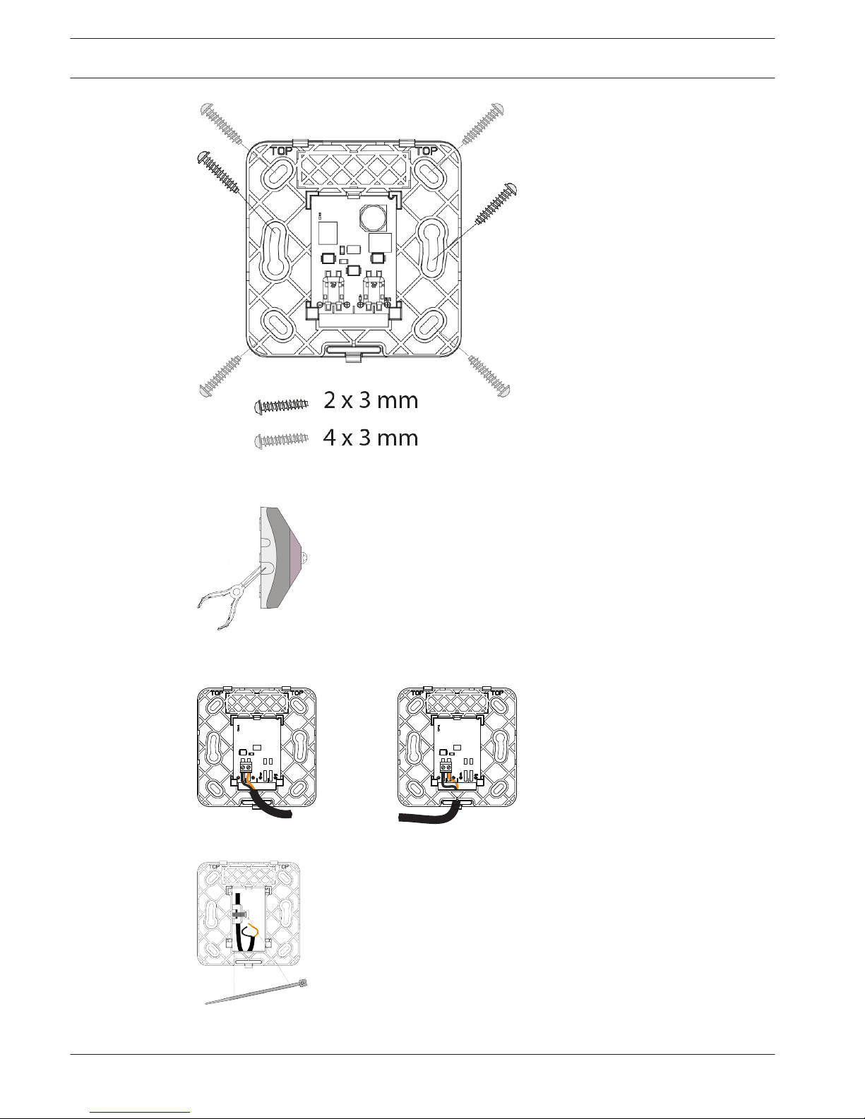
1. For surface-mounted cables, break out the prepunched cable entries.
2. For flush-mounted cables, insert the cable through the opening under the connection
board.
3. Secure the cable with a zip tie on the base plate.
Wiring FAA‑420‑RI‑ROW
1. Wire the remote indicator as shown.
10
en | System Overview AVENAR detector 4000
2014.11 | 1.1 | F.01U.283.550 Operation Guide Bosch Sicherheitssysteme GmbH
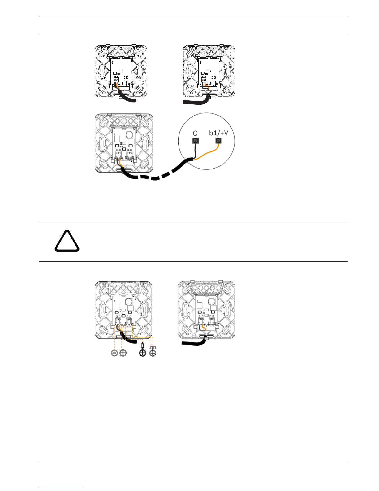
2. Place the cap on the base plate in such a way that the two hooks are inserted into the
slits.
3. Press the cap lightly onto the base plate until the snap‑fit‑hook engages.
Wiring FAA‑420‑RI‑DIN
!
Warning!
Malfunction and Damage
Note the maximum permitted current supply respectively the input voltage range of the
functional modes.
4 Wire the remote indicator as shown.
AVENAR detector 4000 System Overview | en 11
Bosch Sicherheitssysteme GmbH Operation Guide 2014.11 | 1.1 | F.01U.283.550

Mode Terminal connection Alarm condition
1
+
The remote indicator shows steady red light. Current has
to be limited to max. 30 mA.
2
+
The remote indicator shows steady red light. Input voltage
range: 8.5 V DC … 33 V DC. Constant current consumption
13 mA.
3
+
The remote indicator shows flashing red light. Input voltage
range: 11 V DC … 33 V DC. Constant current consumption
3 mA.
Operate in mode 1 and 3 only, when connected to LSN detectors.
1. Place the cap on the base plate in such a way that the two hooks are inserted into the
slits.
2. Press the cap lightly onto the base plate until the snap‑fit‑hook engages.
Notice!
Malfunction
The cable length between the detector and the remote indicator must not exceed 3 m when
connected by an unshielded cable.
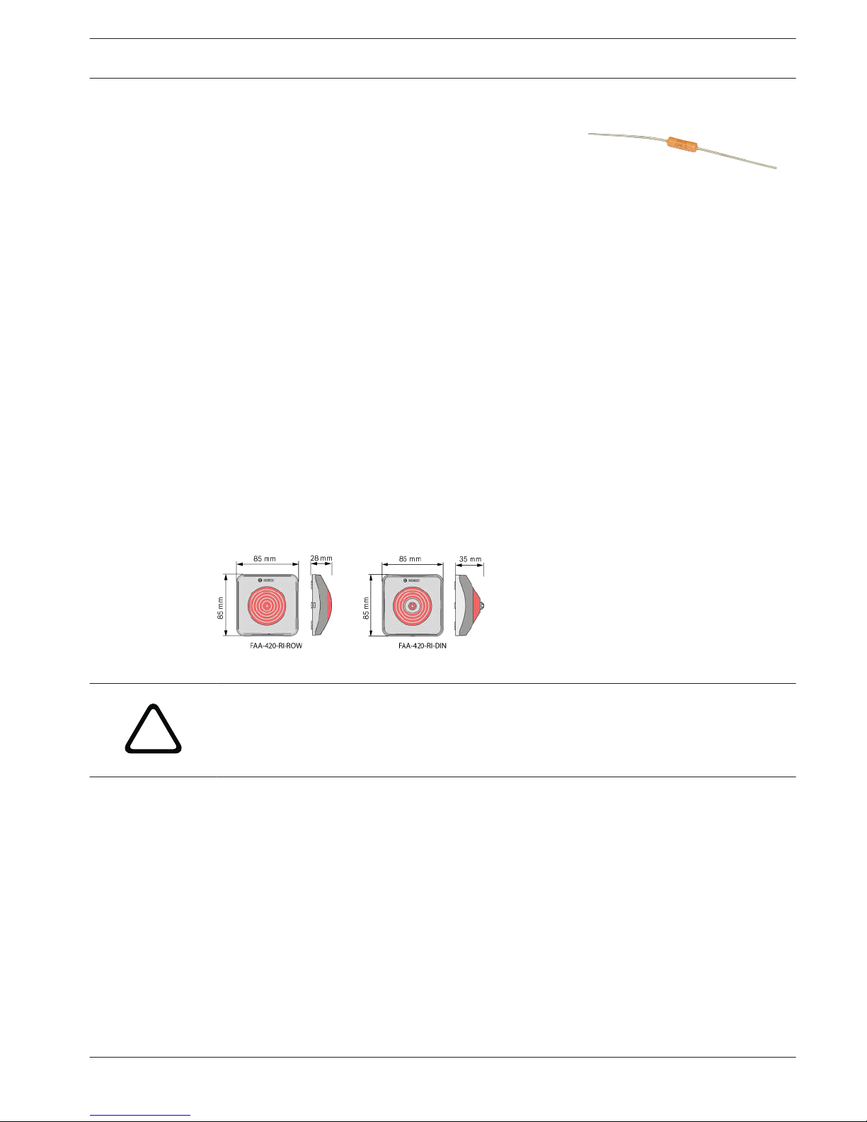
Technical specifications
FAA‑420‑RI‑ROW FAA‑420‑RI‑DIN
Operating Voltage 5 ‑ 30 V DC 9 ‑ 30 V DC
Maximum current
consumption
20 mA Mode 1: limited to 30 mA
Mode 2: 13 mA
Mode 3 : 3 mA
Permissible wire gauge 0,6 – 2 mm 0,6 ‑ 0,8 mm
Display medium 1 LED 2 LED
Dimensions 85 x 85 x 28 mm 85 x 85 x 35 mm
Weight 45 g 65 g
12 en | System Overview AVENAR detector 4000
2014.11 | 1.1 | F.01U.283.550 Operation Guide Bosch Sicherheitssysteme GmbH
 Loading...