


 Loading...
Repair Manual
F 650 GS
BMW AG Motorcycle Division
After Sales
Introduction
This repair manual will help you to perform all the main maintenance and repair work correctly and efficiently. If it is consulted regularly by workshop personnel it will form a useful addition to the theoretical and practical knowledge acquired at the BMW Training Centre. It is a contribution towards achieving even higher Service quality.
A new issue of this repair manual will be published if amendments or additions (supplements) are needed.
All information in both text and illustrations refers to motorcycles in standard condition or with genuine BMW accessories installed, and not to motorcycles which have been modified in any way to depart from the manufacturer’s specification.
•The repair manual is structured in the logical sequence of the work to be performed: Removal, Disassembly, Repair, Assembly, Installation.
•The entire contents are divided into individual chapters, corresponding to the Construction Groups.
|
|
|
|
11 . 10 |
|
|
|
|||||
|
|
|
|
|
|
|
|
|
|
|
|
|
|
|
|
|
|
|
|
|
|
|
|
|
|
|
Chapter |
|
|
|
|
Page number within chapter |
|
|||||
|
|
|||||||||||
|
|
|
||||||||||
An arrow symbol followed by the chapter and page numbers is a reference to another chapter, e.g. Ób ............................................See Group 46
•Work to be performed during an Inspection is described in Group “00”. The various inspection routines are numbered I, II, III and IV. This numbering is repeated in the work descriptions which follow, so that work can take place without interruption.
•Use of the BMW special tools needed for certain tasks is described in the work instructions.
If the need arises, repair instructions are also issued in the form of Service Information. This information is of course incorporated into the next issue of the repair manual. We also recommend, as an additional source of information, the Electronic Parts Catalogue (ETC), which contains clear and easy-to-follow illustrations.
If the work described here is restricted to a particular equipment specification, for instance if a specific optional extra (OE) is fitted, this is stated in square brackets at the start of the item concerned, e.g. [With heated handlebar grips].
Please refer to the following pages as well for a description of other symbols used and how to work with it.
BMW AG Motorcycle Division
After Sales
Published by: |
BMW AG Sparte Motorrad |
|
After Sales |
|
UX-VS-2 |
|
D - 80788 München |
All rights reserved. Not to be reprinted, translated or duplicated either wholly or in part without prior written permission.
Errors and omissions excepted; subject to technical amendment.
Produced in Germany

Usage
Each chapter starts with the list of contents.
The list of contents is followed by the Technical Data table.
Chapter 00 “Maintenance and general instructions” details the handover checklist and lists all tightening torques and operating fluids.
Key to symbols
In this Workshop Manual for the F 650 GS model, the following symbols are used; their meanings are explained in the table.
Special instructions aimed at improving the work procedures
L Note:
Specific information on operating, inspecting and adjusting work for the motorcycle as well as maintenance procedures.
eCaution:
Instructions and precautions specifically intended to prevent damage to the motorcycle. Failure to comply with them could invalidate the warranty.
d Warning:
This symbol stands for precautions and measures which are essential in order to protect the rider or other persons from possibly severe or fatal injury.
Contents
Headlines for the work described in the chapter........................................... |
with the relevant page number |
Activities
•Activities
•The bullet symbol means that work steps are described in greater detail under another headline
–Preceding activities
–A line indicates work steps described in greater detail under another headline or in another chapter
If the term “release” or “remove” is used:
the fastener (e.g. screw) must be slackened off and taken out or
a component (e.g. fuel rail) must be removed to the extent that other components which it conceals (e.g. throttle-valve rail) are accessible
If the term “loosen” or “slacken” is used:
the fastener (e.g. screw) must only be slackened off but not taken out
X Tightening torques:
Values are stated if they differ from DIN EN 24 014 or DIN 912 ISO industrial standards.
BMW AG Motorcycle Division
Maintenance schedule
F 650 GS
|
|
|
|
|
|
Customer |
Licence plate no. |
||
|
|
|
|
|
|
Order No. |
Mechanic’s signature |
||
|
|
|
|
|
Read the fault code memory with the BMW MoDiTeC
Change the engine oil while at regular operating temperature; replace the oil filter element
if motorcycle is used only for short journeys or at outside temperatures below 0°C (32°F): every 3 months or at the latest after 3,000 km (1,800 miles)
Replace oil in telescopic forks
Check the coolant and restore to correct level if necessary *)
Replace the coolant
(every 2 years)
Check valve clearances, adjust if necessary
Replace the spark plug
Drain the outlet hose from the air filter box
Replace intake air filter
If motorcycle is operated in very dirty or dusty conditions, clean or replace the intake air filter every 10,000 km (6,000 miles); check every 3,000 km (1,800 miles)
Replace fuel filter (every 20,000 km/12,000 miles)
Check clutch play, adjust if necessary
Check wheel spoke tension and tighten if necessary
more frequently if motorcycle is ridden in severe off-road conditions
Examine brake pads and discs for wear, replace if necessary *)
more frequently if motorcycle is ridden in severe off-road conditions
Check brake fluid level at front and rear and top up if necessary *)
Check for operation of brake system and freedom from leaks; repair/replace if necessary *)
Replace the brake fluid at least once a year
Replace the primary front/rear brake master cylinder cup (every 40,000 km/24,000 miles on a motorcycle with ABS)
Check wheel bearings and replace if necessary *)
Check or, if necessary, replace chain, sprocket, chain guide rollers and pinion *)
more frequently if motorcycle is ridden in severe off-road conditions
Check chain tension and adjust if necessary *)
Check battery acid level, add distilled water if necessary
more frequently if motorcycle is ridden in severe off-road conditions
Clean and grease the battery terminals, if necessary
Check steering head bearings and adjust *) or replace if necessary *)
Grease the side and main stands
Grease the brake pedal
Check bolts and nuts on engine mountings, frame connections, exhaust system mountings, swinging fork pivot, suspension levers, brake pedal, main and side stands and quick-release axles for tightness
Final inspection with road safety and functional check:
–(Clutch, gearshift)
–Steering
–Front and rear brakes Side stand contact switch
–Condition of tyres and wheels, tyre pressures
–Lights and signalling equipment, indicator and warning lights, instruments
–Test ride, if necessary
*) Associated work invoiced separately, see Flat rates brochure, Motorcycle ’98
BMW Inspection at |
1,000 km (600 miles) |
|
BMW Service every |
10,000 km (6,000 miles) |
|
BMW Inspection every |
20,000 km (12,000 miles) |
|
|
BMW Annual Service |
||||
|
|
|
|
|
|
|
|
|
|
|
|
|
|
|
|
|
|
|
|
|
|
|
|
|
|
|
|
|
|
|
|
|
|
|
|
|
|
|
|
|
|
|
|
|
|
|
|
|
|
|
|
|
|
|
|
|
|
|
|
|
|
|
|
|
|
|
|
|
|
|
|
|
|
|
|
|
|
|
|
|
|
|
|
|
|
|
|
|
|
|
|
|
|
|
|
|
|
|
|
|
|
|
|
|
|
|
|
|
|
|
|
|
|
|
|
|
|
|
|
|
|
|
|
|
|
|
|
|
|
|
|
|
|
|
|
|
|
|
|
|
|
|
|
|
|
|
|
|
|
|
|
|
|
|
|
|
|
|
|
|
|
|
|
|
|
|
|
|
|
|
|
|
|
|
|
|
|
|
|
|
|
|
|
|
|
|
|
|
|
|
|
|
|
|
|
|
|
|
|
|
|
|
|
|
|
|
|
|
|
|
|
|
|
|
|
|
|
|
|
|
|
|
|
|
every 2 years
20,000 km
40,000 km
Order No. 01 71 0 010 183 |
UX-VS-2, 10/99 |
Printed in Germany |

BMW AG Motorcycle Division
Pre-delivery Check
F 650 GS
|
|
|
|
|
Customer |
Licence plate no. |
|||
|
|
|
|
|
Order No. |
Mechanic’s signature |
|||
|
|
|
|
|
Check the shipping crate for damage
Motorcycle:
–unpack
–inspect for damage
–install remaining items
–clean
Battery:
–remove
–add acid
–charge
–grease terminal posts
–fit (mark with fitting date)
Check that the delivery is complete:
–Toolkit
–Documentation
–Motorcycle keys
–Optional extras
Read the fault code memory with the BMW MoDiTeC
Check tyre pressures
Fill fuel tank
Final inspection as functional check:
–Oil inspection
–Engine idle speed
–Clutch, gearshift
–Steering
–Hand brakes and foot brakes
–Check lights and signalling equipment, warning and indicator lights, instruments, ABS
–Test ride, if necessary
BMW
Pre-delivery check
Order No. 01 71 0 010 183 |
UX-VS-2, 10/99 |
Printed in Germany |

BMW AG Motorcycle Division
Service data
F 650 GS
Item |
|
Rated value |
|
Unit of |
|
|
|
|
|
|
|
measurement/ |
|
|
|
|
|
|
specification |
|
|
|
|
|
|
|
|
|
|
|
|
|
|
|
Oil capacities |
|
2.3 (4.05/2.43) |
|
Litres (Imp. pints/US quarts) |
||
Engine (with filter) |
|
|
||||
|
|
|
|
|
Specification: see current |
|
|
|
|
|
|
Service Information |
|
Telescopic fork – for each post |
|
0.60 (1.06/0.63) |
|
Litres (Imp. pints/US quarts) |
||
|
|
|
|
|
BMW telescopic fork oil |
|
|
|
|
|
|
|
|
|
|
|
|
|
|
|
Coolant |
|
1.3 (2.29/1.37) |
|
Litres (Imp. pints/US quarts) |
||
Cooling system (entire) |
|
|
||||
Expansion tank |
|
0.1 (0.18/0.11) |
|
Litres (Imp. pints/US quarts) |
||
|
|
|
|
|
Composition: |
|
|
|
|
|
|
Water: |
50% |
|
|
|
|
|
Antifreeze: |
50% |
|
|
|
|
|
Antifreeze protection |
|
|
|
|
|
|
to –25 °C ( –13 °F) |
|
|
|
|
|
|
|
|
|
|
|
|
|
|
|
Brake fluid |
|
|
|
|
DOT 4 |
|
|
|
|
|
|
|
|
|
|
|
|
|
|
|
Valve clearances |
|
Inlet: |
0.10-0.15 |
|
mm (in) |
|
Measured cold (max. 35 °C/95 °F) |
|
|
(0.004-0.006) |
|
|
|
|
|
Exhaust: 0.25-0.30 |
|
mm (in) |
|
|
|
|
|
(0.010-0.012) |
|
|
|
|
|
|
|
|
|
|
|
|
|
|
|
|
|
Spark plugs |
|
0.6...0.7 (0.02...0.03) |
|
NGK D8 EA |
|
|
Electrode gap |
|
|
mm (in) |
|
||
|
|
|
|
|
|
|
|
|
|
|
|
|
|
Idle speed |
|
|
1350 +100 |
|
rpm |
|
|
|
|
|
|
|
|
|
|
|
|
|
|
|
Clutch cable play |
|
|
1.0 - 2.0 |
|
mm (in) |
|
Hand lever cable |
|
|
|
|
||
|
|
(0.004 - 0.008) |
|
|
|
|
|
|
|
|
|
|
|
|
|
|
|
|
|
|
Tyre pressure (on cold tyres) |
|
|
front/rear |
|
bar (psi) |
|
solo |
|
1.9/2.1 (27/30) |
|
|
||
when fully loaded |
|
2.1/2.3 (30/33) |
|
bar (psi) |
|
|
|
|
|
|
|
|
|
|
|
|
|
|
|
|
Tightening torques: |
|
|
|
|
|
|
Engine oil drain plug |
|
|
40 |
|
Nm |
|
Engine water drain plug |
|
|
10 |
|
Nm |
|
Oil tank drain plug |
|
|
21 |
|
Nm |
|
Oil filter cap |
|
|
10 |
|
Nm |
|
Valve cap |
|
|
10 |
|
Nm |
|
Camshaft bracket |
|
|
10 |
|
Nm |
|
Spark plug |
|
|
20 |
|
Nm |
|
Telescopic fork oil drain plug |
|
|
6 |
|
Nm |
|
Round nut, steering bearing |
|
|
25 |
|
Nm |
|
Steering bearing locking tube |
|
|
65 |
|
Nm |
|
Flanged nut on locking tube |
|
|
65 |
|
Nm |
|
Fork stabilizer clamping screws |
|
|
21 |
|
Nm |
|
Front quick-release axle |
|
|
80 |
|
Nm |
|
Clamping screws for front quick-release axle |
|
|
21 |
|
Nm |
|
Rear quick-release axle |
|
|
100 |
|
Nm |
|
Brake caliper at fork slider tube |
|
|
41 |
|
Nm |
|
Swinging arm bearings |
|
|
100 |
|
Nm |
|
Deflection lever/frame |
|
|
50 |
|
Nm |
|
Deflection lever/spring strut |
|
|
47 |
|
Nm |
|
Deflection lever/tension strut |
|
|
71 |
|
Nm |
|
Swinging fork/tension strut |
|
|
41 |
|
Nm |
|
|
|
|
|
|
|
|
Order No. 01 71 0 010 252 |
UX-VS-2, 10.99 |
Printed in Germany |

F 650 GS
Instructions for pre-delivery check
BMW AG Sparte Motorrad |
|
After Sales |
|
UX-VS-2 |
|
Hufelandstr. 6 |
|
D-80937 München |
Edition: 11/99 |
Contents |
Page |
General view of crated motorcycle .................................................................................... |
3 |
Checking the shipping crate for damage ............................................................................. |
3 |
In case of damage in Germany ................................................................................................. |
3 |
In case of damage in importer markets ................................................................................ |
3 |
Unpacking the motorcycle ...................................................................................................... |
3 |
Inspecting motorcycle for damage .................................................................................... |
4 |
Installing remaining items on motorcycle ...................................................................... |
4 |
Installing windscreen ..................................................................................................................... |
4 |
Installing front mudguard, mirrors and handlebar weights ........................................... |
4 |
Filling and charging the battery ........................................................................................... |
5 |
Removing right and centre covers .......................................................................................... |
5 |
Filling and charging the battery ................................................................................................ |
6 |
Checking that delivery is complete
Reading the fault code memory with the BMW MoDiTeC Checking tyre pressures
Adding fuel to tank
Final inspection and function check
Final cleaning
Handing over the motorcycle
2

E000250 |
General view of crated motorcycle |
• Notify the supplier (e.g. freight company) without |
|
Checking the shipping crate for |
delay. |
|
Unpacking the motorcycle |
||
damage |
•When the motorcycle arrives, check the crate immediately for damage and if necessary examine the contents for consequential damage.
In case of damage in Germany
•Lever off the cover.
•Take out the separate pack of items.
•Force off cross-struts with a suitable lever.
e Caution:
• Note the damage on the delivery slip. |
Do not hammer out the cross-strut panels or the |
•Read the information sheet on damage in transit. motorcycle may be damaged.
•Notify the supplier without delay
(e.g. freight company or DB) and also Bavaria Wirtschaftsagentur GmbH Abteilung ZW - 12
D-80788 München
Tel. 089/14327-632
Fax. 089/14327-639
In case of damage in importer markets
•Note the damage on the delivery slip.
•Comply with specific national market procedures.
In case of doubt, please submit enquiries to: Bavaria Wirtschaftsagentur GmbH
Abteilung ZW - 12
D-80788 München
Tel. +49 (0)89 14327 632 Fax. (+) 89/14327-639
•Remove the end panels.
•Remove the side panels.
e Caution:
Make sure that the motorcycle cannot topple.
• Remove the straps at front and rear.
e Caution:
Remove nails projecting from the base of the crate or lying on the base or on the floor.
3
•Dispose of the packing materials in an environmentally responsible manner as described in Circular 23/91 - Sales.
•Check the contents of the enclosed package:
– Front mudguard with fasteners and washers
–Windshield
–Mirrors with clamping screws and nuts
–Handlebar weights with screws
–Rider's Manual
–Service and Technical booklet
–Booklet listing service centres in Europe
–BMW emergency service sticker
–Handling instructions for batteries
Inspecting motorcycle for damage
•Check for defects.
•Use the “express handling service” to notify BMW AG Sparte Motorrad, UX-VS-1
Fax: 00 49 89 382-33220
•Rectify the fault.
•If parts are needed, order them by using the electronic parts list.
•Costs are to be processed by the warranty claim system (stage 4).
Defect codes:
–Parts missing 10 01 00 00 00
–Parts damaged 10 02 00 00 00
–Incorrect parts delivered 10 03 00 00 00
•If the parts that are needed do not appear in the electronic parts list (e.g. parts for official-user motorcycles),
send an order form to:
Fax number 030-3396-2262
Installing remaining items on motorcycle
Installing windscreen
• Wheel the motorcycle clear of the wooden pallet
.
X Tightening torques:
Windscreen to cockpit fairing ......................... |
2 Nm |
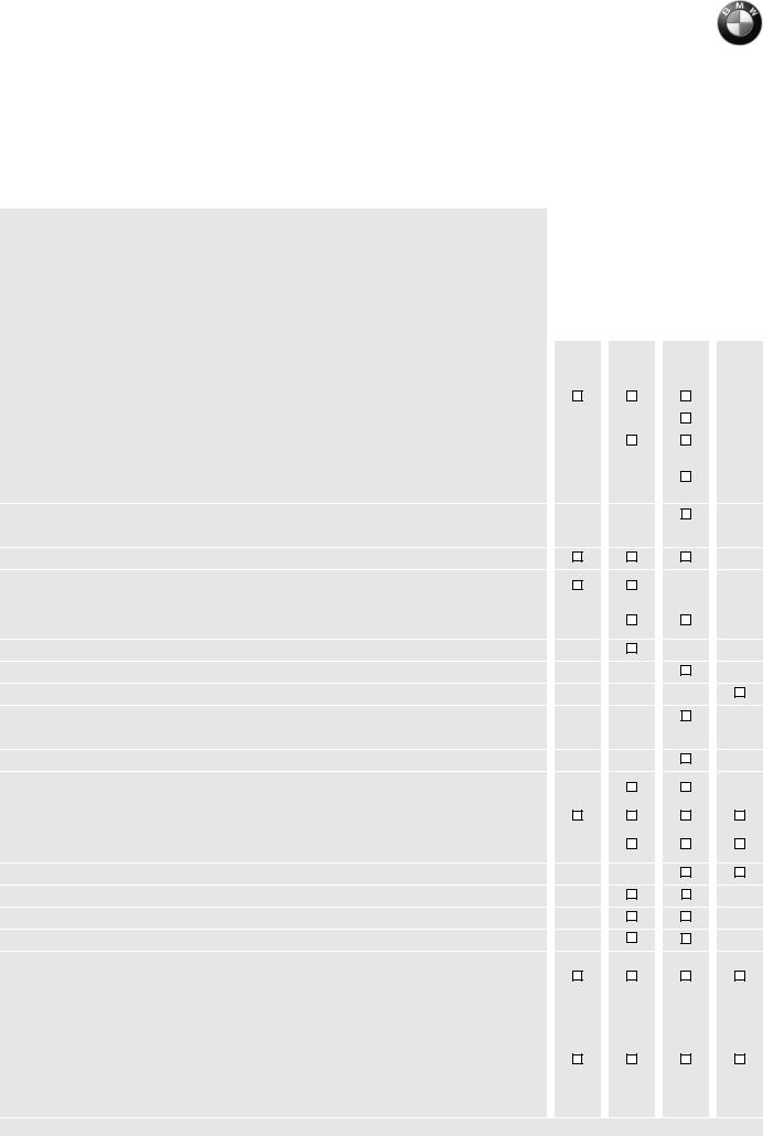
Installing front mudguard, mirrors and handlebar weights
E000270 |
• Install front mudguard. |
3 |
2 |
1 |
E000310 |
• Install handlebar weights (1).
• Tighten clamp screw (2) on handlebar fitting.
• Install each mirror and secure by tightening
nut (3). |
|
|
X Tightening torques: |
|
|
Front mudguard to fork bridge ....................... |
3 |
Nm |
Clamp screw to handlebar fitting.................. |
21 |
Nm |
Union nut of mirror ....................................... |
18 |
Nm |
Handlebar weight to handlebar ...................... |
9 |
Nm |
E000260
• Tighten the windscreen securing screws.
4
5
6
4 |
1 |
|
2
3
E000280
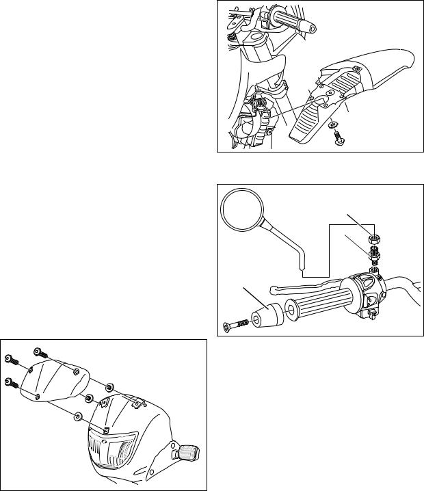
Filling and charging the battery
Removing right and centre covers
L Note:
Do not remove the windscreen after the side panels have been removed, as otherwise the headlight beam setting will have to be checked.
•Remove the lid of the stowage compartment.
•Remove the seat.
•Remove the fasteners securing turn indicator (1).
•Slacken front securing screw (2).
•Remove securing screws (5) from side cover.
•Pull side cover (4) out of the anchorage (arrow) at the bottom and lift it clear of the centre panel at the top.
•Remove securing screws (6) from centre cover.
•Remove centre cover (3).
5

E000290 |
Filling and charging the battery
d Warning:
Battery acid is highly caustic.
Protect your eyes, face, hands, clothing and the paintwork.
•Disengage the rubber strap holding the battery.
•Disconnect the battery breather hose.
•Remove the battery.
•Top up the battery acid to the upper level mark.
•Allow the battery to stand for at least an hour.
•Shake the battery slightly to allow the remaining air bubbles to escape.
•If necessary, top up again to the upper level mark with battery acid.
•Recharge the battery and allow to stand for 24 hours.
Charge current (amps)
.........................10 % of rated battery capacity (Ah)
•Check the acid level and, if necessary, top up with distilled water to the upper level mark.
•Make a note of the charging date on the battery.
eCaution:
Connect the positive battery terminal first, then the negative terminal.
•Apply acid-proof grease to the battery terminal posts.
•Install the battery.
•Install right and centre covers.
•Install seat.
X Tightening torques: |
|
Right/left covers with centre cover |
|
to mounting frame .......................................... |
2 Nm |
Right/left covers to centre cover .................... |
2 Nm |
Centre cover to main frame at front................ |
2 Nm |
6
Checking that delivery is complete Adding fuel to tank
•All optional extras
•Toolkit:
–Reversible screwdriver
–Small star screwdriver
–3 open-ended wrenches a/f 8×10, 14×19, 24
–Extension for open-ended wrenches
–Spark plug wrench
–Wrench for socket-head screws, a/f 8
–3 Torx wrenches Torx T25, T30, T45
–3 fuses
7.5A, 15A, 20A
•Documentation
•Motorcycle keys, 3
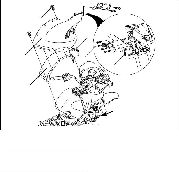
Reading the fault code memory with the BMW MoDiTeC
1
E000340
•Unclip diagnosis plug (1) behind cover on right.
•Connect the diagnosis unit to the diagnosis plug.
•Read out the fault memory.
•Perform all requisite repair work.
•Clip diagnosis plug into position behind cover on right.
Checking tyre pressures
• Check/correct tyre pressures.
Tyre pressures: |
|
Solo ..................................... |
front 1.9 bar (27.0 psi) |
............................................. |
rear 2.1 bar (29.9 psi) |
With full load......................... |
front 2.1 bar (29.9 psi) |
............................................. |
rear 2.3 bar (32.7 psi) |
• Fill up with fuel.
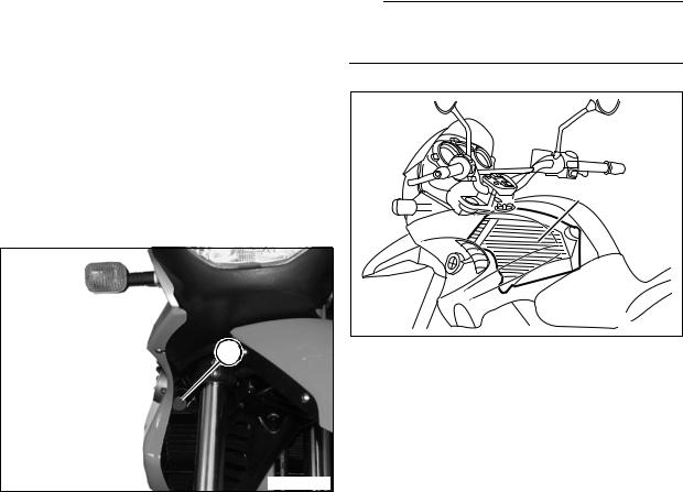
Final inspection and function check
L Note:
When the motorcycle arrives, the oil level in the tank might be below the sight glass.
2
E000300
•Oil check: if oil is not visible in the sight glass, check whether the oil tank (2) contains oil.
•Clutch
•Check gear shift action.
•Steering
•Front and rear brakes
•Check lights and signalling equipment:
•Front and rear parking lights
•Instrument lighting
•Low and high headlight beams, headlight flasher
•Brake light (operate brake at front and rear)
•Turn signals left/right
•Horn
•Telltale and warning lights
•Instruments
•As applicable, check function of optional extras:
•ABS: perform starting test. In the event of a fault in the system, the ABS warning light comes on as soon as the motorcycle is ridden for at least 10 seconds at a speed of 30 km/h
(approx. 20 mph) or more.
•If necessary, take the motorcycle for a test ride.
•Confirm pre-delivery check in Service and Technical Booklet.
•See “Inspecting motorcycle for damage” if defects are detected.
7
Final cleaning
• Clean the motorcycle.
L Note:
Do not use a steam or high-pressure water jet. The high steam or water pressure could damage seals, the hydraulic system or electrical components.
L Note:
The number-plate carrier is not pre-drilled so that number plates of any shape can be set to the best possible position.
Handing over the motorcycle
This is the ideal opportunity to familiarise the customer with the motorcycle in order to ensure the customer’s satisfaction and safety.
• The following points must be demonstrated and explained to the customer:
–documentation and stowage space
–toolkit and stowage space
–suspension preload adjustment to suit total weight
–checking brake fluid
–how to adjust the mirrors
–controls
–instruments and telltale lights
–optional equipment and accessories fitted
• The user must be given the following information:
–running-in recommendations and inspection intervals
–safety check
8
Contents
<< Back
Group / Chapter |
|
|
00 |
Maintenance and general instructions ................................................ |
00.1 |
11 |
Motor....................................................................................................... |
11.1 |
12 |
Engine electrics ..................................................................................... |
12.1 |
13 |
Fuel preparation and control ................................................................ |
13.1 |
16 |
Fuel tank and lines................................................................................. |
16.1 |
17 |
Radiator .................................................................................................. |
17.1 |
18 |
Exhaust system ...................................................................................... |
18.1 |
21 |
Clutch...................................................................................................... |
21.1 |
23 |
Gearbox................................................................................................... |
23.1 |
27 |
Drive chain............................................................................................... |
27.1 |
W
B
>> Continuation
|
>> Continuation |
|
|
|
Group / Chapter |
|
|
|
|
32 |
Steering |
32.1 |
|
|
|
|
|||
33 |
Rear wheel drive |
33.1 |
|
|
|
|
|||
34 |
Brakes |
34.1 |
|
|
|
|
|||
36 |
Wheels and tyres |
36.1 |
|
|
|
|
|||
46 Frame |
46.1 |
|
|
|
|
|
|||
51 |
Equipment |
51.1 |
|
|
|
|
|||
61 |
General electrical equipment |
61.1 |
|
|
|
|
|||
62 |
Instruments |
62.1 |
|
|
|
|
|||
63 |
Lights |
63.1 |
|
|
|
|
|||
|
|
|
|
|
|
|
|
|
|
<< Back

00
00 Maintenance and general instructions
Contents |
Page |
Table of operating fluids ........................................................................................................... |
5 |
Tightening torques ...................................................................................................................... |
6 |
Key to maintenance intervals .............................................................................................. |
15 |
Reading the fault code memory with the MoDiTeC ................................................ |
16 |
(Inspections I, II, III and IV) ................................................................................................................. |
16 |
Changing the engine oil and oil filter element ............................................................ |
16 |
(Inspections I, II, III and IV) ................................................................................................................. |
16 |
Preparatory work ........................................................................................................................... |
16 |
Draining engine oil ........................................................................................................................ |
16 |
Replacing oil filter element ........................................................................................................ |
17 |
Filling with engine oil .................................................................................................................... |
17 |
Checking coolant, topping up if necessary ................................................................. |
18 |
(Inspections I, II and III) ...................................................................................................................... |
18 |
Checking coolant .......................................................................................................................... |
18 |
Adding coolant ............................................................................................................................... |
18 |
Changing coolant ....................................................................................................................... |
18 |
(Inspection IV, every 2 years) ............................................................................................................. |
18 |
Changing oil in telescopic forks ........................................................................................ |
20 |
(Inspection III) .................................................................................................................................... |
20 |
Checking and adjusting valve clearances .................................................................... |
21 |
(Inspections I, II and III) ...................................................................................................................... |
21 |
Checking valve clearances ....................................................................................................... |
21 |
Preparatory work ............................................................................................................................... |
21 |
Removing the intake air silencer together with the intake air pipe ...................................................... |
21 |
Exposing the radiator ........................................................................................................................ |
21 |
Exposing cylinder head ..................................................................................................................... |
21 |
Turning crankshaft to TDC position ................................................................................................... |
21 |
Checking valve clearance .................................................................................................................. |
22 |
00.1

Contents |
Page |
Adjusting valve clearances ....................................................................................................... |
22 |
Installing cylinder head cover ............................................................................................................ |
23 |
Installing fan shroud .......................................................................................................................... |
23 |
Installing intake air silencer ................................................................................................................ |
23 |
Installing the intake air duct ............................................................................................................... |
23 |
Replacing spark plugs ............................................................................................................. |
24 |
(Inspection III) .................................................................................................................................... |
24 |
Emptying drain hose from intake air silencer ............................................................. |
24 |
(Inspections II and III) ......................................................................................................................... |
24 |
Replacing air cleaner element ............................................................................................ |
24 |
(Inspection III) .................................................................................................................................... |
24 |
Replacing fuel filter ................................................................................................................... |
25 |
(Inspection III, every 20,000 km/12,000 miles) ................................................................................... |
25 |
Checking clutch play, adjusting if necessary ............................................................. |
26 |
(Inspections I, II and III) ...................................................................................................................... |
26 |
Checking wheel spoke tension, adjusting if necessary ........................................ |
26 |
(Inspection II) ..................................................................................................................................... |
26 |
Checking brake pads and discs for wear, replacing if necessary .................. |
27 |
(Inspections II and III) ......................................................................................................................... |
27 |
Checking brake pads for wear ................................................................................................ |
27 |
Brake pads, front brake ..................................................................................................................... |
27 |
Brake pads, rear brake ...................................................................................................................... |
27 |
Replacing brake pads ................................................................................................................. |
27 |
Brake pads, front brake ..................................................................................................................... |
27 |
Brake pads, rear brake ...................................................................................................................... |
28 |
Checking the brake discs ......................................................................................................... |
28 |
Checking the brake fluid level and topping up if necessary .............................. |
28 |
(Inspection II) ..................................................................................................................................... |
28 |
Brake fluid level (front brake) .................................................................................................... |
28 |
Checking brake fluid level (front brake) .............................................................................................. |
28 |
Topping up brake fluid level (front brake) ........................................................................................... |
28 |
Brake fluid level (rear brake) ..................................................................................................... |
29 |
Checking brake fluid level (rear brake) ............................................................................................... |
29 |
Topping up brake fluid level (rear brake) ............................................................................................ |
29 |
Checking operation of brake system and freedom from leaks, repairing/ |
|
replacing if necessary .............................................................................................................. |
29 |
(Inspection III) .................................................................................................................................... |
29 |
Changing brake fluid ................................................................................................................. |
30 |
(Inspection IV) .................................................................................................................................... |
30 |
Changing brake fluid (front brake) ......................................................................................... |
30 |
Changing brake fluid (rear brake) ........................................................................................... |
30 |
00.2
Contents |
Page |
Replacing primary sealing boot, front brake master cylinder ........................... |
31 |
(Inspection III, every 40,000 km/24,000 miles for motorcycles with ABS) .......................................... |
31 |
Replacing primary sealing boot, rear brake master cylinder ............................. |
32 |
(Inspection III, every 40,000 km/24,000 miles for motorcycles with ABS) .......................................... |
32 |
Inspecting front and rear wheel bearings, replacing if necessary ................. |
33 |
(Inspection III) .................................................................................................................................... |
33 |
Checking chain, chainwheel and chain sprocket, replacing if necessary .33 |
|
(Inspections II and III) ......................................................................................................................... |
33 |
Checking chain tension, adjusting if necessary ........................................................ |
33 |
(Inspections I, II, III and IV) ................................................................................................................. |
33 |
Checking chain tension
Adjusting chain tension
..............................................................................................................33
..............................................................................................................34
Checking battery acid level, adding distilled water if necessary .................... |
34 |
(Inspections II, III and IV) .................................................................................................................... |
34 |
Checking battery acid level ...................................................................................................... |
34 |
Adding distilled water .................................................................................................................. |
34 |
Cleaning and greasing the battery terminals, if necessary ................................. |
35 |
(Inspections III and IV) ....................................................................................................................... |
35 |
Checking and adjusting steering head bearing play, |
|
replacing if necessary .............................................................................................................. |
35 |
(Inspections II and III) ......................................................................................................................... |
35 |
Checking steering head bearing play .................................................................................. |
35 |
Checking and adjusting steering head bearing play, |
|
replacing if necessary .............................................................................................................. |
36 |
(Inspections II and III) ......................................................................................................................... |
36 |
Adjusting steering head bearing play ................................................................................... |
36 |
Greasing the side and main stands and the brake pedal lever ........................ |
37 |
(Inspections II and III) ......................................................................................................................... |
37 |
Side stand ........................................................................................................................................ |
37 |
Main (centre) stand ....................................................................................................................... |
37 |
Brake pedal ..................................................................................................................................... |
38 |
Checking security of threaded fasteners ...................................................................... |
38 |
(Inspections I, II, III and IV) ................................................................................................................. |
38 |
Final inspection with road safety and functional check ....................................... |
39 |
(Inspections I, II, III and IV) ................................................................................................................. |
39 |
Road safety check ............................................................................................................................ |
39 |
Tyre tread depth (recommended minimum value) .............................................................................. |
39 |
Tyre pressures (tyres cold) ................................................................................................................ |
39 |
Roadworthiness check ...................................................................................................................... |
39 |
00.3

00.4

00
Table of operating fluids
Item |
Use |
Order number |
Quantity |
|
|
|
|
|
|
|
|
Lubricant |
|
|
|
|
|
|
|
|
|
|
|
Staburags NBU 30 PTM |
High-performance lubricating paste |
07 55 9 056 992 |
75 g tube |
|
|
|
|||||
|
|
|
|
|
|
Optimoly MP 3 |
High-performance lubricating paste |
07 55 9 062 476 |
100 g tube |
|
|
|
|
|
|
|
|
Optimoly TA |
High-temperature assembly paste |
18 21 9 062 599 |
100 g tube |
|
|
|
|
|
|
|
|
Silicone grease 300, heavy |
Damping grease |
07 58 9 058 193 |
10 g tube |
|
|
|
|
|
|
|
|
Retinax EP2 |
Wheel, steering head and taper roller |
83 22 9 407 845 |
100 g tube |
|
|
|
bearing grease |
|
|
|
|
Contact spray |
Contact spray |
81 22 9 400 208 |
300 ml spray |
|
|
|
|
|
|
|
|
Chain spray |
Drive chain |
72 60 2 316 676 |
50 ml spray |
|
|
72 60 2 316 667 |
300 ml spray |
|
|
||
|
|
|
|
||
|
|
|
|
|
|
Sealants |
|
|
|
|
|
|
|
|
|
|
|
3-Bond 1110 B |
Surface sealant |
07 58 9 056 998 |
5 g tube |
|
|
|
|
|
|
|
|
3-Bond 1209 |
Surface sealant |
07 58 9 062 376 |
30 g tube |
|
|
|
|
|
|
|
|
omni VISC 1002 |
Surface sealant (max. 200 °C/392 °F) |
07 58 1 465 170 |
90 g tube |
|
|
|
|
|
|
|
|
Loctite 574 |
Surface sealant |
81 22 9 407 301 |
50 ml tube |
|
|
|
|
|
|
|
|
Curil K 2 |
Heat-conductive sealant |
81 22 9 400 243 |
250 g can |
|
|
|
|
|
|
|
|
Hylomar SQ 32 M |
Permanently elastic sealant |
81 22 9 400 339 |
100 g tube |
|
|
|
|
|
|
|
|
Adhesives and retainers |
|
|
|
|
|
|
|
|
|
|
|
Loctite 648 |
Joint adhesive (low clearance) |
07 58 9 067 732 |
5 g bottle |
|
|
|
|
|
|
|
|
Loctite 638 |
Joint adhesive (greater clearance) |
07 58 9 056 030 |
10 ml bottle |
|
|
|
|
|
|
|
|
Loctite 243 |
Thread retainer, medium-strength |
07 58 9 056 031 |
10 ml bottle |
|
|
|
|
|
|
|
|
Loctite 270 |
Thread retainer, strong |
81 22 9 400 086 |
10 ml bottle |
|
|
|
|
|
|
|
|
Loctite 2701 |
Thread retainer, strong |
33 17 2 331 095 |
10 ml bottle |
|
|
|
|
|
|
|
|
Loctite 454 |
Cyanacrylate adhesive (gel) |
07 58 9 062 157 |
20 g tube |
|
|
|
|
|
|
|
|
Cleaners |
|
|
|
|
|
|
|
|
|
|
|
Brake cleaner |
Brake cleaner |
83 11 9 407 848 |
600 ml spray |
|
|
|
|
|
|
|
|
Metal Polish |
Polish for parts |
82 14 9 400 890 |
100 g tube |
|
|
|
|
|
|
|
|
Testing agents |
|
|
|
|
|
|
|
|
|
|
|
Penetrant MR 68 |
Crack testing agent for aluminium |
83 19 9 407 855 |
500 ml spray |
|
|
housings |
|
|
|||
|
|
|
|
|
|
|
|
|
|
|
|
Developer MR 70 |
Crack testing agent for aluminium |
81 22 9 407 495 |
500 ml spray |
|
|
housings |
|
|
|||
|
|
|
|
|
|
|
|
|
|
|
|
Installation aid |
|
|
|
|
|
|
|
|
|
|
|
BMW chilling spray |
Chilling components before assembly |
83 19 9 407 762 |
300 ml spray |
|
|
|
|
|
|
|
|
00.5

Tightening torques
|
|
Model |
F 650 GS |
|
|
|
|
|
|
Connection |
Nm |
|
|
|
|
|
|
11 Engine |
|
|
|
|
|
|
|
Freewheel housing and freewheel |
35 (clean thread + Loctite 648) |
|
|
|
|
|
|
Engine block |
10 |
|
|
|
|
|
|
Double drive gear on crankshaft |
180 (clean thread + Loctite 243) |
|
|||
|
|
|
|
|
|
Driver |
140 (clean thread + Loctite 243) |
|
|
|
|
|
|
Pressure plate |
10 |
|
|
|
|
|
|
Magnet hub |
180 (clean thread + Loctite 243) |
|
|
|
|
|
|
Signal transmitter |
8 |
|
|
|
|
|
|
Ignition cover |
10 |
|
|
|
|
|
|
Cylinder base |
10 |
|
|
|
|
|
|
Spark plug |
20 |
|
|
|
|
|
|
Threaded connection for chain tensioner |
40 |
|
|
|
|
|
|
Oil circuit |
|
|
|
|
|
|
|
Oil tank to intake air silencer |
9 |
|
|
|
|
|
|
Oil filter cover |
10 |
|
|
|
|
|
|
Oil pressure switch |
12 (clean thread + Loctite 243) |
|
|
|
|
|
|
Oil tank drain plug |
21 |
|
|
|
|
|
|
Engine oil drain plug |
40 |
|
|
|
|
|
|
Oil supply/oil return lines to engine |
35 |
|
|
|
|
|
|
Oil pump cover |
6 (clean thread + Loctite 243) |
|
|
|
|
|
|
Oil pressure valve |
24 |
|
|
|
|
|
|
Oil retaining valve |
24 |
|
|
|
|
00

Model |
F 650 GS |
|
|
|
|
|
|
Connection |
Nm |
|
|
|
|
|
|
Cylinder head |
|
|
|
|
|
|
|
Collar nuts for cylinder head |
60 |
|
|
|
|
|
|
Collar screws for cylinder head |
33 |
|
|
|
|||
|
|
|
|
Machine screws (chaincase) |
10 |
|
|
|
|
|
|
Camshaft mount |
10 |
|
|
|
|
|
|
Chain sprockets to camshafts |
60 threads oiled |
|
|
|
|||
|
|
|
|
Chain guide to camshaft mount |
10 (clean thread + Loctite 243) |
|
|
|
|
|
|
Cylinder head cover |
10 |
|
|
|
|
|
|
Machine screw (hole for locating pin) |
25 |
|
|
|
|
|
|
Cylinder head to frame |
41 |
|
|
|
|
|
|
Cylinder head to frame, adjusting sleeve |
zero play, max. 5 |
|
|
|
|
|
|
Cylinder head to frame, locknut |
100 |
|
|
|
|
|
|
12 Engine electrics |
|
|
|
|
|
|
|
Magnet hub |
180 (clean thread + Loctite 243) |
|
|
|
|
|
|
Signal transmitter |
8 |
|
|
|
|
|
|
Engine block cover, left/right |
10 |
|
|
|
|
|
|
Starter to clutch cover |
10 |
|
|
|
|
|
|
Necked-down bolts, starter housing |
6 |
|
|
|
|
|
|
Cable cover to engine block |
4 |
|
|
|
|
|
|
Ignition coil and holder |
9 |
|
|
|
|
|
|
00.7

|
|
Model |
F 650 GS |
|
|
|
|
|
|
Connection |
Nm |
|
|
|
|
|
|
13 Fuel preparation and control |
|
|
|
|
|
|
|
Air intake connection to cylinder head |
25 |
|
|||
|
|
|
|
|
|
Fuel filter to frame |
9 |
|
|
|
|
|
|
Injector holder to throttle valve |
5 |
|
|
|
|
|
|
Connecting flange, air filter box to battery carrier |
5 |
|
|||
|
|
|
|
|
|
Intake air silencer to retainer |
9 |
|
|
|
|
|
|
Oil tank to intake air silencer |
9 |
|
|
|
|
|
|
Throttle-valve potentiometer to throttle flap stub |
3 |
|
|
|
|
|
|
Throttle lifter to throttle flap stub |
5 (clean thread + Loctite 243) |
|
|
|
|
|
|
16 Fuel tank and lines |
|
|
|
|
|
|
|
Fuel tank to rear frame (M 8 stud) |
21 |
|
|
|
|
|
|
Tank cover to fuel tank |
3 |
|
|
|
|
|
|
Roll-over valve to fuel tank |
2 |
|
|
|
|
|
|
Bracket, activated charcoal filter to fuel tank |
3 |
|
|
|
|
|
|
Fuel pump to fuel tank |
36 |
|
|
|
|
|
|
17 Radiator |
|
|
|
|
|
|
|
Air duct to frame trussing |
3 |
|
|
|
|
|
|
Expansion tank to radiator |
9 |
|
|
|
|
|
|
Radiator to main frame |
9 |
|
|
|
|
|
|
Water pump drain screw |
10 |
|
|
|
|
|
|
Left engine block cover to engine block |
10 |
|
|
|
|
|
|
Water pump cover |
10 |
|
|
|
|
|
|
Temperature sensor in cylinder head |
15 |
|
|
|
|
|
|
Bleed screw |
12 |
|
|
|
|
00

Model |
F 650 GS |
|
|
|
|
|
|
Connection |
Nm |
|
|
|
|
|
|
18 Exhaust system |
|
|
|
|
|
|
|
Oxygen sensor to exhaust |
45 |
|
|
|
|||
|
|
|
|
Exhaust manifold to cylinder head |
20 |
|
|
|
|
|
|
Silencer to exhaust manifold (Torca clamp) |
55 |
|
|
|
|
|
|
Silencer to rear frame |
21 |
|
|
|
|||
|
|
|
|
Guard to silencer |
9 |
|
|
|
|
|
|
21 Clutch |
|
|
|
|
|
|
|
Driver |
140 (clean thread + Loctite 243) |
|
|
|
|
|
|
Pressure plate |
10 |
|
|
|
|
|
|
Engine block cover, left |
10 |
|
|
|
|
|
|
23 Transmission |
|
|
|
|
|
|
|
Selector lever to selector shaft |
13 |
|
|
|
|
|
|
27 Drive chain |
|
|
|
|
|
|
|
Drive pinion cover to engine |
2 |
|
|
|
|
|
|
Chain takeup roller to frame |
21 |
|
|
|
|
|
|
Chain sprocket to chain sprocket carrier |
21 |
|
|
|
|
|
|
Quick-release shaft nut |
100 |
|
|
|
|
|
|
Drive chain tensioning screws |
10 |
|
|
|
|
|
|
Central nut to main shaft |
140 (clean thread + Loctite 243) |
|
|
|
|
|
|
00.9

|
|
Model |
F 650 GS |
|
|
|
|
|
|
Connection |
Nm |
|
|
|
|
|
|
31 Front forks |
|
|
|
|
|
|
|
Fork stabiliser to fork leg |
21 |
|
|||
|
|
|
|
|
|
Clamp screws for fork bridges, top/bottom |
21 |
|
|
|
|
|
|
Plate for bottom fork bridge to fork bridge |
9 |
|
|
|
|
|
|
Oil drain plug |
6 |
|
|||
|
|
|
|
|
|
Damper retaining screw |
20 |
|
|
|
|
|
|
Knurled nut/bearing preload |
25 |
|
|
|
|
|
|
Locknut at upper fork bridge |
65 |
|
|
|
|
|
|
32 Steering |
|
|
|
|
|
|
|
Handlebar to fork bridge |
21 |
|
|
|
|
|
|
Handlebar weight to handlebar |
9 |
|
|
|
|
|
|
Clutch fitting to handlebar, M 6 |
9 |
|
|
|
|
|
|
Clutch switch to handlebar fitting |
5 |
|
|
|
|
|
|
Pivot pin for brake lever |
6 |
|
|
|
|
|
|
Locknut for pivot pin, clutch lever |
8 |
|
|
|
|
|
|
33 Rear wheel drive |
|
|
|
|
|
|
|
Suspension strut to frame |
50 |
|
|
|
|
|
|
Suspension strut to angled lever |
47 |
|
|
|
|
|
|
Knob for adjusting suspension-strut damping to holder |
21 |
|
|
|
|
|
|
Holder, suspension-strut damping to frame |
9 |
|
|
|
|
|
|
Swinging fork pivot shaft |
100 |
|
|
|
|
|
|
Tension strut to swinging fork |
41 |
|
|
|
|
|
|
Tension strut to angled lever |
71 |
|
|
|
|
|
|
Angled lever to frame |
50 |
|
|
|
|
00

Model |
F 650 GS |
|
|
|
|
|
|
Connection |
Nm |
|
|
|
|
|
|
34 Brakes |
|
|
|
|
|
|
|
Bleed screw in front/rear brake calliper |
7 |
|
|
|
|||
|
|
|
|
Brake calliper to fork slider tube |
41 |
|
|
|
|
|
|
Brake disc and sensor ring to front wheel |
9 (clean thread + Loctite 243) |
|
|
|
|
|
|
Brake disc to rear wheel |
9 (clean thread + Loctite 243) |
|
|
|
|||
|
|
|
|
Brake fluid reservoir for rear brake to rear frame |
1.5 |
|
|
|
|
|
|
Brake pedal to frame |
21 |
|
|
|
|
|
|
Brake lines/hoses |
|
|
|
|
|
|
|
Brake hose to brake calliper |
18 |
|
|
|
|
|
|
Brake hose to brake lever fitting |
18 |
|
|
|
|
|
|
Brake hose/brake line interfaces |
18 |
|
|
|
|
|
|
Brake line to master brake cylinder, rear wheel |
18 |
|
|
|
|
|
|
ABS |
|
|
|
|
|
|
|
ABS sensor front/rear |
9 |
|
|
|
|
|
|
ABS pressure modulator to holder |
21 |
|
|
|
|
|
|
Holder for ABS pressure modulator to frame trans- |
|
|
|
verse tube |
9 |
|
|
|
|
|
|
Brake line to ABS pressure modulator |
18 |
|
|
|
|
|
|
Sensor ring to rear wheel |
5 (clean thread + Loctite 243) |
|
|
|
|
|
|
Brake disc and sensor ring to front wheel |
9 (clean thread + Loctite 243) |
|
|
|
|
|
|
36 Wheels and tyres |
|
|
|
|
|
|
|
Clamp nut, front quick-release axle |
21 |
|
|
|
|
|
|
Front quick-release axle to fork leg |
80 |
|
|
|
|
|
|
Rear quick-release axle to swinging arm |
100 |
|
|
|
|
|
|
Chain sprocket to chain sprocket carrier |
21 |
|
|
|
|
|
|
00.11

|
|
Model |
F 650 GS |
|
|
|
|
|
|
Connection |
Nm |
|
|
|
|
|
|
46 Frame |
|
|
|
|
|
|
|
Body |
|
|
|
||
|
|
|
|
|
|
Fairing sections/covers |
3 |
|
|
|
|
|
|
Fairing support bracket to frame |
21 |
|
|
|
|
|
|
Grip to rear frame |
9 |
|
|||
|
|
|
|
|
|
End trimmer to rear frame |
9 |
|
|
|
|
|
|
Tail to rear frame |
3 |
|
|
|
|
|
|
Seat lock to rear frame |
9 |
|
|
|
|
|
|
Number-plate carrier to rear section of rear mudguard |
3 |
|
|
|
|
|
|
Mudguards/wheel guards |
|
|
|
|
|
|
|
Front mudguard, rear section to front section |
3 |
|
|
|
|
|
|
Front mudguard to fork bridge |
3 (clean thread + Loctite 243) |
|
|
|
|
|
|
Rear mudguard, front and rear sections to rear frame |
9 |
|
|
|
|
|
|
Rear mudguard, front section to bracket for case car- |
|
|
|
rier |
21 |
|
|
|
|
|
|
Wheel cover, bottom, to bracket |
3 |
|
|
|
|
|
|
Wheel cover bracket to swinging arm |
9 |
|
|
|
|
|
|
Frame |
|
|
|
|
|
|
|
Footrest plate to main frame |
21 |
|
|
|
|
|
|
Footrest rubber to rear footrest |
5 |
|
|
|
|
|
|
Retaining bracket for intake air silencer to main frame |
9 |
|
|
|
|
|
|
Engine guard to frame trussing |
9 |
|
|
|
|
|
|
Rear frame to main frame, top |
21 |
|
|
|
|
|
|
Rear frame to main frame, bottom |
21 (clean thread + Loctite 2701) |
|
|
|
|
|
|
Centre stand to main frame |
41 |
|
|
|
|
|
|
Side stand undersection to main frame |
21 |
|
|
|
|
|
|
Engine mounts |
|
|
|
|
|
|
|
Engine/crankcase to main frame at rear |
41 |
|
|
|
|
|
|
Engine/cylinder head to main frame at top |
41 |
|
|
|
|
|
|
Engine/crankcase to engine mounting at front |
41 |
|
|
|
|
|
|
Engine mounting to main frame |
21 |
|
|
|
|
00
Loading...