

Page 1
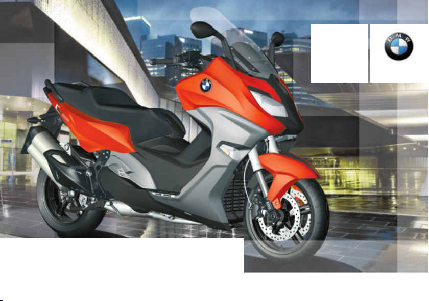
Rider's Manual (US Model)
C 650 Sport
BMW Motorrad
bmw‑motorrad.com
The Ultimate
Riding Machine
Page 2

Motorcycle/Retailer Data
Motorcycle Data
Model
Vehicle identification number
Color number
Initial registration
License plate
Retailer Data
Contact in Service
Ms./Mr.
Phone number
Retailer's address/phone number (company stamp)
Page 3

Welcome to BMW
We congratulate you on your
choice of a Maxi-Scooter from
BMW and welcome you to the
community of BMW riders.
Please read this Rider's Manual
carefully before starting to use
your new Maxi-Scooter. It contains important information on
operation that enables you to
make the best possible use of all
your Scooter's technical features.
In addition, it contains information
on maintenance and care to help
you maintain your motorcycle's
reliability and safety, as well as its
value.
If you have any questions concerning the Maxi-Scooter communication system, your authorized BMW Motorrad retailer is
always happy to provide you with
advice and assistance.
We hope that you enjoy your
BMW Maxi-Scooter and wish you
a safe and pleasant journey
BMW Motorrad.
01 40 8 382 507
*01408382507*
Page 4

Table of Contents
1 General instructions ... . 5
Overview . . . . . . . . . . . . . . . . . . . . . 6
Abbreviations and
symbols . . . . . . . . . . . . . . . . . . . . . . 6
Equipment . . . . . . . . . . . . . . . . . . . 7
Technical data . . . . . . . . . . . . . . . 7
Notice concerning current sta-
tus . . . . . . . . . . . . . . . . . . . . . . . . . . . 7
2 Overviews . .. .. .. .. ... ... . 9
General view, left side . . . . . . . 11
General view, right side . . . . . 13
Underneath seat . . . . . . . . . . . . 14
Multifunction switch, left . . . . 15
Multifunction switch,
right . . . . . . . . . . . . . . . . . . . . . . . . . 16
Cockpit . . . . . . . . . . . . . . . . . . . . . . 17
3 Displays . ... . .. . .. .. .. .. . 19
Indicator and warning
lights . . . . . . . . . . . . . . . . . . . . . . . . 20
Multifunction display . . . . . . . . 21
Warning lights . . . . . . . . . . . . . . . 22
Service display . . . . . . . . . . . . . . 37
Distance traveled since fuel
reached reserve level . . . . . . . . 38
Oil level indicator . . . . . . . . . . . . 38
Outside temperature . . . . . . . . 38
Tire inflation pressures . . . . . . 39
4 Operation . .. . .. .. .. .. .. . . 41
Steering and ignition
lock . . . . . . . . . . . . . . . . . . . . . . . . . 42
Emergency on/off switch (kill
switch) . . . . . . . . . . . . . . . . . . . . . . 43
Lights . . . . . . . . . . . . . . . . . . . . . . . 43
Hazard warning lights sys-
tem . . . . . . . . . . . . . . . . . . . . . . . . . 44
Turn indicators . . . . . . . . . . . . . . 45
Display . . . . . . . . . . . . . . . . . . . . . . 45
SETUP . . . . . . . . . . . . . . . . . . . . . . 47
Time and date .. . . . . . . . . . . . . 48
Automatic Stability Control
(ASC) . . . . . . . . . . . . . . . . . . . . . . . 50
Anti-theft alarm (DWA) . . . . . . 52
Heated handlebar grips . . . . . 54
Seat heating . . . . . . . . . . . . . . . . 54
Seat . . . . . . . . . . . . . . . . . . . . . . . . . 56
Tank cover . . . . . . . . . . . . . . . . . . 56
Storage compartments . . . . . . 57
5 Setting .. .. .. .. .. . .. .. .. .. 59
Mirrors . . . . . . . . . . . . . . . . . . . . . . 60
Headlight . . . . . . . . . . . . . . . . . . . . 60
Windshield . . . . . . . . . . . . . . . . . . 60
Brakes . . . . . . . . . . . . . . . . . . . . . . 61
Spring preload . . . . . . . . . . . . . . 61
6 Riding .. .. .. .. .. . .. .. .. .. . 63
Safety instructions .. . . . . . . . . 64
Observe checklist . . . . . . . . . . . 66
Starting. . . . . . . . . . . . . . . . . . . . . . 66
Riding . . . . . . . . . . . . . . . . . . . . . . . 68
Running in . . . . . . . . . . . . . . . . . . 69
Brakes . . . . . . . . . . . . . . . . . . . . . . 69
Maxi-Scooter Parking . . . . . . . 70
Refueling . . . . . . . . . . . . . . . . . . . . 71
Secure motorcycle for trans-
port . . . . . . . . . . . . . . . . . . . . . . . . . 73
Page 5

7 Technology in
detail .. . .. .. .. .. .. . .. .. .. . 75
General instructions . . . . . . . . . 76
Antilock Brake System
(ABS). . . . . . . . . . . . . . . . . . . . . . . . 76
Automatic Stability Control
(ASC) . . . . . . . . . . . . . . . . . . . . . . . 78
Tire pressure control
(TPC/RDC) . . . . . . . . . . . . . . . . . . 79
8 Maintenance . . . .. .. . .. .. 81
General instructions . . . . . . . . . 82
Standard tool kit. . . . . . . . . . . . . 82
Front wheel stand . . . . . . . . . . . 82
Engine oil . . . . . . . . . . . . . . . . . . . 84
Brake system . . . . . . . . . . . . . . . 86
Coolant. . . . . . . . . . . . . . . . . . . . . . 91
Tyres . . . . . . . . . . . . . . . . . . . . . . . . 93
Wheel rims and tyres . . . . . . . . 93
Wheels . . . . . . . . . . . . . . . . . . . . . . 94
Fuses . . . . . . . . . . . . . . . . . . . . . . . 99
Light sources . . . . . . . . . . . . . 101
Jump-starting . . . . . . . . . . . . . 107
Battery . . . . . . . . . . . . . . . . . . . . 108
Fairings and panels . . . . . . . 110
Diagnostic connector . . . . . . 113
9 Accessories . .. .. .. . .. . 115
General instructions . . . . . . . 116
Onboard power
sockets . . . . . . . . . . . . . . . . . . . . 116
Topcase. . . . . . . . . . . . . . . . . . . 117
Scooter lock. . . . . . . . . . . . . . . 119
Navigation system . . . . . . . . . 120
10 Care . . .. .. .. .. .. . .. .. . 123
Care products . . . . . . . . . . . . . 124
Washing your motorcy-
cle. . . . . . . . . . . . . . . . . . . . . . . . . 124
Cleaning sensitive motorcy-
cle parts . . . . . . . . . . . . . . . . . . . 125
Paint . . . . . . . . . . . . . . . . . . . . . . 125
Paint preservation . . . . . . . . . 126
Maxi-Scooter Storage . . . . . 126
Maxi-Scooter Returning to
use . . . . . . . . . . . . . . . . . . . . . . . . 126
11 Technical data . . . .. . 127
Troubleshooting chart . . . . . 128
Threaded fasteners . . . . . . . 129
Fuel . . . . . . . . . . . . . . . . . . . . . . . 130
Fuel . . . . . . . . . . . . . . . . . . . . . . . 130
Engine oil . . . . . . . . . . . . . . . . . 131
Engine . . . . . . . . . . . . . . . . . . . . 132
Clutch . . . . . . . . . . . . . . . . . . . . . 133
Transmission . . . . . . . . . . . . . . 133
Rear-wheel drive . . . . . . . . . . 133
Frame . . . . . . . . . . . . . . . . . . . . . 134
Suspension . . . . . . . . . . . . . . . 134
Brakes . . . . . . . . . . . . . . . . . . . . 135
Wheels and tyres . . . . . . . . . . 136
Electrical system . . . . . . . . . . 137
Alarm system . . . . . . . . . . . . . 139
Dimensions .. . . . . . . . . . . . . . 140
Weights . . . . . . . . . . . . . . . . . . . 140
Performance data . . . . . . . . . 141
12 Service . . .. . .. .. .. .. .. 143
Reporting safety
defects . . . . . . . . . . . . . . . . . . . . 144
BMW Motorrad Service . . . 145
BMW Motorrad Mobility
Services . . . . . . . . . . . . . . . . . . . 145
Maintenance proce-
dures . . . . . . . . . . . . . . . . . . . . . . 145
Maintenance schedule . . . . 149
Confirmation of mainte-
nance work . . . . . . . . . . . . . . . . 150
Confirmation of service . . . . 164
Page 6

13 Appendix . .. .. .. .. . .. . 167
Certificate . . . . . . . . . . . . . . . . . 168
14 Index . .. .. .. .. .. .. .. .. 169
Page 7

General instructions
Overview . . . . . . . . . . . . . . . . . . . . . . . . . . . . 6
Abbreviations and symbols . . . . . . . . . . 6
Equipment . . . . . . . . . . . . . . . . . . . . . . . . . . . 7
Technical data . . . . . . . . . . . . . . . . . . . . . . . 7
Notice concerning current status . . . . 7
1
5
z
General instructions
Page 8
Overview
1
You will find an overview of your
Maxi-Scooter in Chapter 2 of the
6
Owner's Handbook. All maintenance and repair work carried
out on your vehicle will be documented in Chapter 12. Documentation confirming performance of scheduled maintenance is a precondition for generous handling of out-of-warranty
claims and goodwill warranty
treatment.
When the time comes to sell
your MaxiScooter, please remember to hand over this Rider's
Manual; it is an important part of
z
General instructions
your motorcycle.
Abbreviations and symbols
CAUTION Hazard with
low risk. Failure to avoid
this hazard can result in minor or
moderate injury.
WARNING Hazard with
moderate risk. Failure to
avoid this hazard can result in
death or serious injury.
DANGER Hazard with high
risk. Failure to avoid this
hazard results in death or serious
injury.
ATTENTION Special in-
structions and precautionary measures. Non-compliance
can cause damage to the vehicle or accessories and warranty
claims may be denied as a result.
NOTICE Special informa-
tion on operating and inspecting your motorcycle as well
as maintenance and adjustment
procedures.
Indicates the end of an
item of information.
Instruction.
Result of an activity.
Reference to a page with
more detailed information.
Indicates the end of accessory or equipmentdependent information.
Tightening torque.
Technical data.
OE Optional extra.
BMW Motorrad optional
extras are already completely installed during
motorcycle production.
Page 9

OA Optional accessory.
BMW Motorrad optional accessories can
be purchased and installed at your authorized BMW Motorrad
retailer.
Electronic immobilizer.
EWS
DWA
Anti-theft alarm.
ABS Anti-Lock Brake System.
ASC Automatic Stability Con-
trol.
CVT Continuously variable
transmission.
Transmission with steplessly adjustable ratio
TPC Tire Pressure Control
(TPC/RDC).
Equipment
When you ordered your MaxiScooter, you chose various items
of custom equipment. This Rider's Manual describes optional
equipment (OE) offered by BMW
and selected optional accessories
(OA). This explains why the manual may also contain descriptions
of equipment which you have not
ordered. Please note, too, that
your vehicle might not be exactly
as illustrated in this manual on
account of country-specific differences.
If your MaxiScooter is equipped
with options or accessories not
described in this Rider's Manual,
then this equipment is described
in separate operating instructions.
Technical data
All dimensions, weights and performance data contained this
Rider's Manual refer to the German DIN standards and comply
with their tolerance specifications.
Versions for individual countries
may differ.
Notice concerning current status
The high safety and quality
standards of BMW Scooters
are maintained by constant
development work on designs,
equipment and accessories.
Because of this, your motorcycle
may differ from the information
supplied in the Rider's Manual. In
addition, BMW Motorrad cannot
guarantee the total absence
of errors. We hope you will
appreciate that no claims can be
recognized based on the data,
1
7
z
General instructions
Page 10

illustrations or descriptions in this
manual.
1
8
z
General instructions
Page 11

Overviews
General view, left side . . . . . . . . . . . . . . . 11
General view, right side . . . . . . . . . . . . . 13
Underneath seat . . . . . . . . . . . . . . . . . . . . 14
Multifunction switch, left . . . . . . . . . . . . 15
Multifunction switch, right . . . . . . . . . . . 16
Cockpit . . . . . . . . . . . . . . . . . . . . . . . . . . . . . 17
2
9
z
Overviews
Page 12
2
10
z
Overviews
Page 13

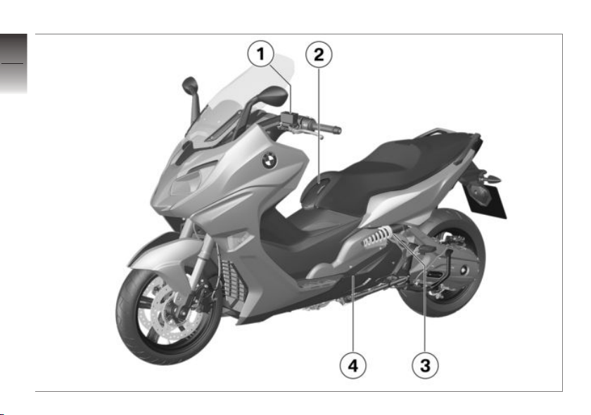
General view, left side
1 Brake-fluid reservoir for
rear brake ( 90)
2 Fuel filler opening (under
the tank cover) ( 71)
3 Adjusting spring preload
( 61)
4 Oil filler opening and oil
dipstick (under the footboard) ( 84)
2
11
z
Overviews
Page 14
2
12
z
Overviews
Page 15

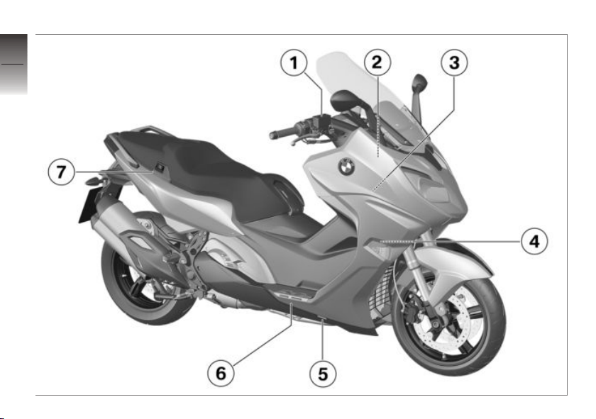
General view, right side
1 Brake-fluid reservoir for
front brake ( 89)
2 Type plate (on the right of
the head tube)
3 Under the fairing side
panel:
Battery ( 108)
Fuses ( 99)
Diagnostic connector
( 113)
4 Vehicle identification num-
ber (on the right-hand
frame tube)
5 Coolant level indicator
(through cutout in fairing
side panel) ( 91)
6 Coolant expansion tank
(under the step plate support) ( 92)
7 Operating passenger seat
heater ( 55)
2
13
z
Overviews
Page 16
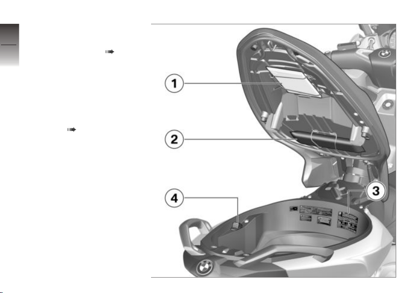
Underneath seat
2
1 Rider's Manual (US Model)
2 Onboard tool kit ( 82)
14
3 Load capacity table
Tyre inflation pressure table
Note on calibrating the
ASC
4 Release of rear storage
compartment (BMW Flexcase) ( 57)
z
Overviews
Page 17
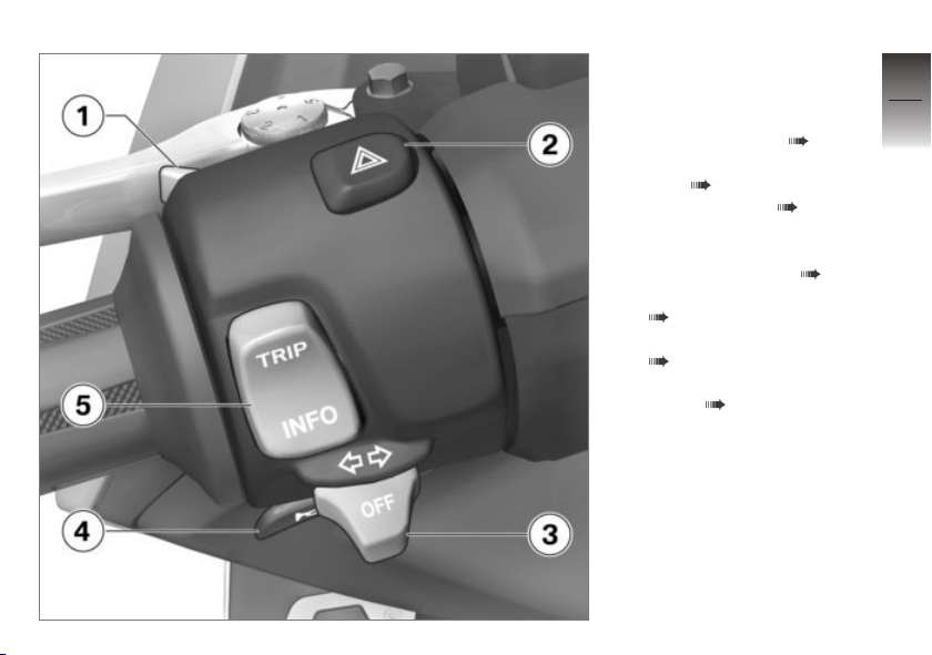
Multifunction switch, left
1 High-beam headlight and
headlight flasher ( 44)
2 Hazard warning lights sys-
tem ( 44)
3 Turn indicators ( 45)
4 Horn
5 TRIP/INFO rocker switch
Selecting displays ( 45)
Resetting trip odometer
( 46)
Resetting average data
( 46)
Calling up the SETUP
menu ( 47)
2
15
z
Overviews
Page 18
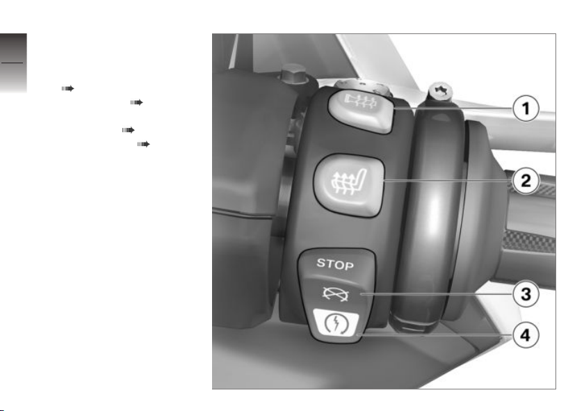
Multifunction switch,
2
right
16
1 Heated handlebar grips
( 54)
2 Seat heating ( 54)
3 Emergency on/off switch
(kill switch) ( 43)
4 Starter button ( 66)
z
Overviews
Page 19

Cockpit
1 Speedometer
2 Multifunction display
( 21)
Warning and indicator
lights ( 20)
3 Windshield adjustment
( 60)
4 Storage compartment
( 57)
5 Tank cover release (inte-
grated in steering and ignition lock) ( 71)
6 Seat bench release (in-
tegrated in steering and
ignition lock) ( 56)
7 Storage compartment
( 57)
Outlet (in the storage compartment) ( 116)
8 Connector for optional ac-
cessories (under the handlebar fairing)
2
17
z
Overviews
Page 20

2
18
z
Overviews
Page 21

Displays
Indicator and warning lights . . . . . . . . . 20
Multifunction display . . . . . . . . . . . . . . . . 21
Warning lights . . . . . . . . . . . . . . . . . . . . . . 22
Service display . . . . . . . . . . . . . . . . . . . . . . 37
Distance traveled since fuel reached
reserve level . . . . . . . . . . . . . . . . . . . . . . . . 38
Oil level indicator. . . . . . . . . . . . . . . . . . . . 38
Outside temperature . . . . . . . . . . . . . . . . 38
Tire inflation pressures . . . . . . . . . . . . . . 39
3
19
z
Displays
Page 22
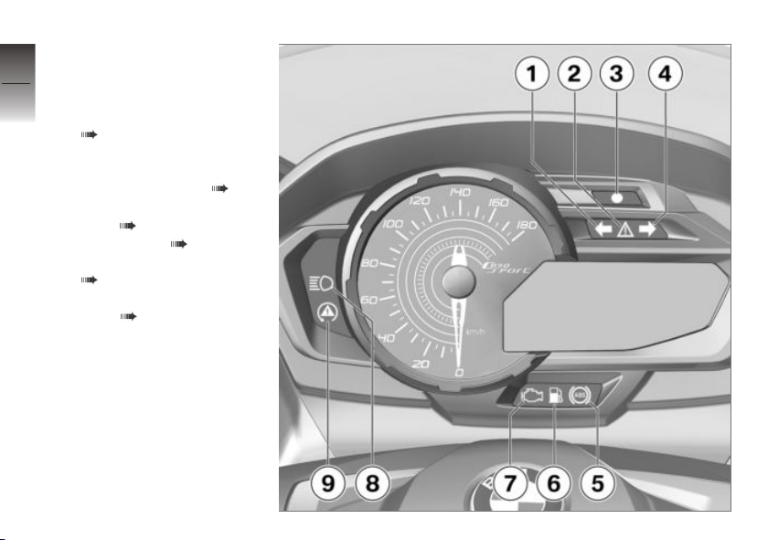
Indicator and warning
3
lights
20
1 Turn indicator, left
2 General warning light
( 22)
3 Photosensor for detecting
ambient brightness
Alarm system LED ( 53)
4 Turn indicator, right
5 ABS ( 30)
z
Displays
6 Fuel reserve ( 36)
7 Emission warning light
( 28)
8 High-beam headlamp
9 ASC ( 31)
Page 23
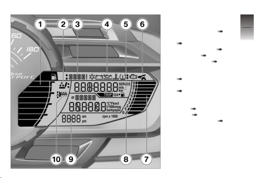
Multifunction display
1 Fuel fill level indicator
2 Set heating stage ( 54)
3 Text field for warnings
( 22)
4 Warning symbols ( 22)
5 Tripmeter ( 46)
Service display ( 37)
Display of distance driven
since reaching fuel reserve
( 38)
6 Rear storage compartment
( 57)
7 Tachometer
8 Onboard computer dis-
plays ( 45)
9 Clock ( 48)
10 Set heating stage ( 54)
3
21
z
Displays
Page 24
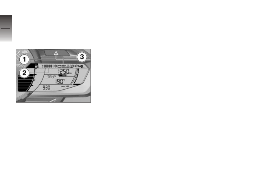
Warning lights
3
Display
22
Warnings are displayed with appropriate warning lights.
z
Displays
Warnings for which no separate warning light is provided are
signaled by the general warning light 1 which is accompanied by a warning notice in position 2 such as EWS! or a warning symbol 3 in the multifunction
display.
The universal warning light lights
up in either yellow or red de-
pending on the urgency of the
warning.
If several warnings are active, all
corresponding warning lights and
warning symbol are displayed;
warnings appear alternately.
You will find an overview of the
potential warnings on the following pages.
Page 25
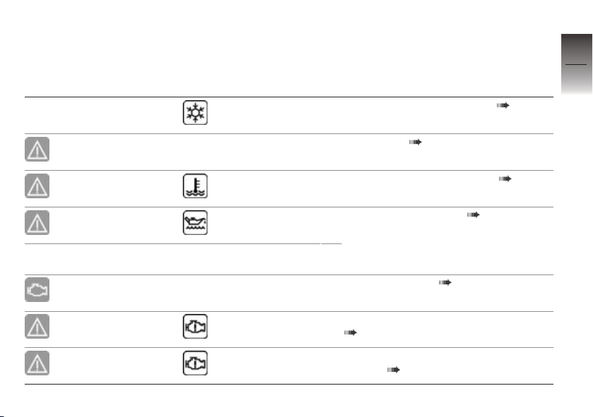
Overview of warning indicators
Indicator and warning
lights
lights up yellow
Warning symbols in the
display panel
appears on the
display
EWS! is indicated
Meaning
Outside temperature warning ( 27)
EWS active ( 27)
3
23
lights up red appears on the
display
lights up yellow appears on the
display
Coolant temperature too high ( 27)
Engine oil level too low ( 28)
OIL CHECK is
indicated
lights up yellow Emission warning ( 28)
lights up yellow appears on the
lights up yellow
display
flashes Severe fault in the engine management
Engine in emergency-operation mode
( 28)
system ( 29)
z
Displays
Page 26
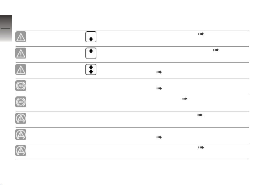
Indicator and warning
3
lights
24
z
Displays
lights up yellow
lights up yellow
lights up yellow
flashes ABS self-diagnosis not completed
lights up
flashes rapidly ASC intervention ( 31)
Warning symbols in the
display panel
+ LAMP! is displayed
+ LAMP! is displayed
+ LAMP! is displayed
Meaning
Taillight defective ( 29)
Headlight bulb defective ( 29)
Tail light and headlight bulb defective
( 30)
( 30)
ABS error ( 30)
flashes slowly ASC self-diagnosis not completed
lights up
( 31)
ASC switched off ( 31)
Page 27
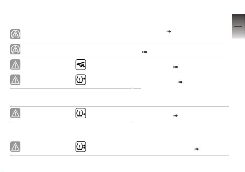
Indicator and warning
lights
lights up
Warning symbols in the
display panel
Meaning
ASC error ( 31)
3
25
lights up
lights up yellow appears on the
flashes red
flashes red
flashes red
CAL. flashes. ASC calibration not yet completed
display
appears on the
display
The critical tire
inflation pressure
flashes
appears on the
display
The critical tire
inflation pressure
flashes
appears on the
display
( 31)
Rear storage compartment (BMW Flexcase) opened ( 32)
Front tire inflation pressure is outside
approved range ( 32)
Rear tire inflation pressure is outside approved range ( 33)
Tire inflation pressure of both tires is
outside approved range ( 33)
z
Displays
Page 28
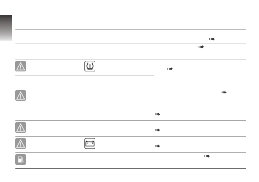
Indicator and warning
3
lights
26
lights up yellow appears on the
z
Displays
lights up yellow
Warning symbols in the
display panel
tire inflation pressures flash
"--" or "--:--"
is indicated
display
"--" or "--:--"
is indicated
RDC! is indicated
Meaning
Tire inflation pressure of both tires is
outside approved range ( 33)
Transmission error ( 34)
TPC/RDC sensor defective or system
fault ( 35)
TPC/RDC sensor battery low ( 35)
DWA! is displayed
lights up yellow
lights up red appears on the
lights up Fuel down to reserve ( 36)
DWA! is displayed
display
Anti-theft alarm battery low charge
( 35)
Anti-theft alarm battery discharged
( 36)
Battery charge current insufficient
( 36)
Page 29
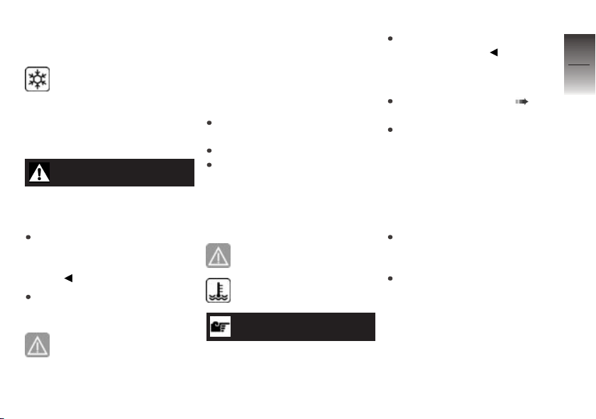
Outside temperature
warning
Ice crystal symbol appears
on the display.
Possible cause:
The ambient temperature mea-
sured at the vehicle is lower than
37 °F (3 °C).
WARNING
Risk of black ice, even above
37 °F (3 °C)
Accident hazard
At a low outside temperature,
icy conditions must expected
on bridges and in shady road
areas.
Think well ahead when driving.
EWS active
General warning light shows
yellow.
EWS! is indicated.
Possible cause:
The ignition key being used is
not authorized for start up, or
communication between the ignition key and engine electronics is
disrupted.
Remove other ignition keys
located on the ignition key.
Use the second ignition key.
Have the defective ignition
key replaced, preferably by a
BMW Motorrad partner.
Coolant temperature too
high
General warning light shows
red.
Temperature symbol is displayed.
ATTENTION
Riding with overheated engine
Engine damage
Be sure to observe the measures listed below.
Possible cause:
Coolant level is too low.
Checking coolant level ( 91).
If coolant level is too low:
Have the coolant system
checked at a specialist service
facility, preferably an authorized
BMW Motorrad retailer.
Possible cause:
The coolant or engine oil temper-
ature too high.
If possible, continue driving
in the part-load range to cool
down the engine.
Should the coolant or engine
oil temperature frequently be
too high, have the fault rectified
as quickly as possible by an
authorized workshop, preferably
an authorized BMW Motorrad
retailer.
3
27
z
Displays
Page 30
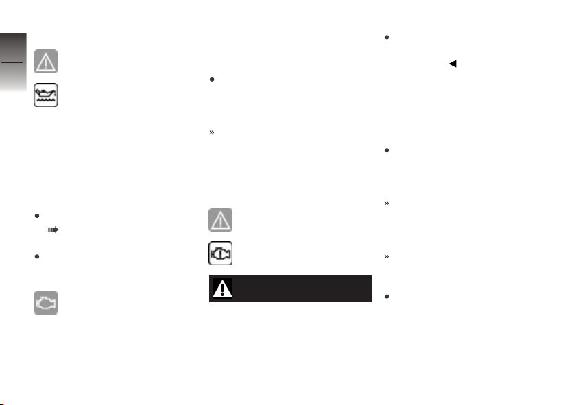
Engine oil level too low
3
28
General warning light shows
yellow.
Oil level symbol appears on
the display.
OIL CHECK is indicated.
Possible cause:
The electronic oil level sensor
has detected that the engine's
oil level is too low. Check the
z
Displays
oil level on the oil dipstick at the
next refueling stop:
Checking engine oil level
( 84).
If oil level is too low:
Top up engine oil.
Emission warning
The malfunction indicator
lamp lights up yellow.
Possible cause:
The engine control unit has diag-
nosed a fault.
Have the fault eliminated at
your convenience at a specialist workshop, preferably a
BMW Motorrad partner.
You may continue to drive if
the pollutant emission is above
the setpoint values.
Engine in emergencyoperation mode
General warning light shows
yellow.
Engine symbol appears on
the display.
WARNING
Unusual handling when engine is in emergency operating mode
Accident hazard
Adapt riding style: avoid rapid
acceleration and passing
maneuvers.
Possible cause:
The engine control unit has di-
agnosed a fault. The engine is
running in the emergency-operation mode.
Continued driving is possible,
however the accustomed engine performance may not be
available.
If the pollutant emission is
above the setpoint values, the
malfunction indicator lamp also
lights up.
In exceptional cases, the engine stops and can no longer
be started.
Have the malfunction corrected
as soon as possible at an
authorized service facility,
preferably an authorized
BMW Motorrad Retailer.
Page 31
Severe fault in the engine
management system
General warning light shows
yellow.
The engine symbol flashes.
WARNING
Damage to the engine when
it is in the emergency operating mode
Accident hazard
Adapt riding style: ride slowly,
avoid rapid acceleration and
passing maneuvers.
If possible, have the motorcycle
picked up and the malfunction
source eliminated by a specialized service facility, preferably
an authorized BMW Motorrad
Retailer.
Possible cause:
The engine control unit has di-
agnosed a fault, which may lead
to severe secondary faults (e.g.
overheating). The engine is in
the emergency-operation mode.
Avoid high load and engine
speed ranges if possible.
Continued driving is not recommended.
If the pollutant emission is
above the setpoint values, the
malfunction indicator lamp also
lights up.
Have the malfunction corrected
as soon as possible at an
authorized service facility,
preferably an authorized
BMW Motorrad Retailer.
Taillight defective
General warning light shows
yellow.
+ LAMP! is displayed.
Possible cause:
Taillight defective.
The diode taillight must be replaced. Please contact a specialized workshop, preferably
an authorized BMW Motorrad
retailer.
Headlight bulb defective
General warning light shows
yellow.
+ LAMP! is displayed.
3
29
z
Displays
Page 32
3
30
z
Displays
WARNING
Overlooking the vehicle in
traffic due to a defective light
source on the vehicle
Safety risk
Replace defective bulbs as
soon as possible; it is best
always to carry a complete
set of spare bulbs on the
motorcycle.
Possible cause:
Low-beam headlight or high-
beam headlight defective.
Replacing bulbs for low-beam
and high-beam headlight
( 101).
Possible cause:
Parking light defective.
Replacing parking light bulb
( 102).
Tail light and headlight
bulb defective
General warning light shows
yellow.
+ LAMP! is displayed.
Possible cause:
The tail light and one headlight
bulb are defective.
See the fault descriptions
above.
ABS self-diagnosis not
completed
ABS warning lamp flashes.
Possible cause:
The self-diagnosis routine
was not completed; the ABS
function is not available. The
MaxiScooter must reach a
speed of at least 3 mph (5 km/h)
before ABS self-diagnosis can be
completed.
Ride off slowly. It must be
noted that the ABS function
is not available until the selfdiagnosis has been completed.
ABS error
ABS warning lamp lights
up.
Possible cause:
The ABS control unit has de-
tected an error. The ABS function is not available.
Continued driving is possible
while taking the failed ABS
function into account. Observe
additional information on situations which can lead to an ABS
error ( 77).
Have the malfunction corrected
as soon as possible at an authorized workshop, preferably
an authorized BMW Motorrad
retailer.
Page 33
ASC intervention
ASC warning light flashes
rapidly.
ASC has detected instability at
the rear wheel and responded by
reducing the torque. The ASC
warning light flashes longer than
the ASC intervention lasts. This
feature continues to furnish the
rider with visual feedback confirming that the system has initiated active closed-loop intervention even after the critical situation has passed.
ASC self-diagnosis not
completed
ASC warning light flashes
slowly.
Possible cause:
ASC self-diagnosis routine not completed
The MaxiScooter must reach
a specified minimum speed
with the engine running before
the system can check operation of the wheel speed sensors:
min 3 mph (min 5 km/h)
Ride off slowly. It must be
noted that the ASC function
is not available until the selfdiagnosis has been completed.
ASC switched off
ASC warning light lights up.
Possible cause:
The ASC system has been deac-
tivated by the rider.
Switch on ASC ( 51).
ASC error
ASC warning light lights up.
Possible cause:
The ASC control unit has de-
tected an error.
It remains possible to continue
riding. It must be noted that
the ASC function is not available. You should also take account of the additional information on situations that can lead
to an ASC fault ( 78).
Have the malfunction corrected
as soon as possible at an
authorized service facility,
preferably an authorized
BMW Motorrad Retailer.
ASC calibration not yet
completed
ASC warning light lights up.
CAL. flashes.
3
31
z
Displays
Page 34
Possible cause:
3
The ASC calibration is not yet
completed
32
Finish or repeat ASC
calibration.
Calibrating ASC ( 51).
Canceling ASC calibration:
Switch the ignition on and off.
Rear storage
compartment (BMW
z
Displays
Flexcase) opened
General warning light shows
yellow.
The storage compartment
is displayed.
Possible cause:
The storage compartment under
the seat bench (BMW Flexcase)
is opened.
WARNING
Storage compartment open
during the journey.
Accident hazard
Stop as soon as possible and
check the storage compartment lock.
Do not drive with the storage
compartment open.
Close the storage compartment (BMW Flexcase).
Front tire inflation
pressure is outside
approved range
with Tire Pressure Control
(TPC/RDC)
played.
The critical tire-inflation pressure
flashes.
OE
General warning light
flashes red.
Tire symbol with arrow
pointing upward is dis-
Possible cause:
The measured front tire inflation
pressure is outside the permissible tolerance.
Check tire for damage and
suitability for continued use.
If it is still possible to drive with
tire:
WARNING
Tire inflation pressure is outside approved range.
Poorer handling characteristic of
the motorcycle.
Adapt your style of riding
accordingly.
Correct tire inflation pressure at
the next opportunity.
NOTICE
Before adjusting the tire inflation
pressure, observe the information
on temperature compensation
and on inflation pressure adjust-
Page 35
ment in the chapter "Technology
in detail".
Have the tire checked for damage at an authorized service
facility, preferably an authorized
BMW Motorrad retailer.
If you are unsure about the tire's
suitability for continued riding:
Do not continue riding.
Contact roadside service.
Rear tire inflation
pressure is outside
approved range
with Tire Pressure Control
(TPC/RDC)
played.
The critical tire-inflation pressure
flashes.
OE
General warning light
flashes red.
Tire symbol with arrow
pointing downward is dis-
Possible cause:
The measured rear tire inflation
pressure is outside the permissible tolerance.
Check tire for damage and
suitability for continued use.
If it is still possible to drive with
tire:
WARNING
Tire inflation pressure is outside approved range.
Poorer handling characteristic of
the motorcycle.
Adapt your style of riding
accordingly.
Correct tire inflation pressure at
the next opportunity.
NOTICE
Before adjusting the tire inflation
pressure, observe the information
on temperature compensation
and on inflation pressure adjust-
ment in the chapter "Technology
in detail".
Have the tire checked for damage at an authorized service
facility, preferably an authorized
BMW Motorrad retailer.
If you are unsure about the tire's
suitability for continued riding:
Do not continue riding.
Contact roadside service.
Tire inflation pressure
of both tires is outside
approved range
with Tire Pressure Control
(TPC/RDC)
ward is displayed.
Tire inflation pressures flash.
OE
General warning light
flashes red.
Tire symbol with arrows
pointing upward and down-
3
33
z
Displays
Page 36

Possible cause:
3
The measured tire inflation pressure of both tires is outside the
34
permissible tolerance.
Check tire for damage and
suitability for continued use.
Are the tires still suitable for driving:
WARNING
Tire inflation pressure is out-
z
Displays
side approved range.
Poorer handling characteristic of
the motorcycle.
Adapt your style of riding
accordingly.
Correct tire inflation pressure at
the next opportunity.
NOTICE
Before adjusting the tire inflation
pressure, observe the information
on temperature compensation
and on inflation pressure adjust-
ment in the chapter "Technology
in detail".
Have the tire checked for damage at an authorized service
facility, preferably an authorized
BMW Motorrad retailer.
If you are unsure about the drivability of the tires:
Do not continue riding.
Contact roadside service.
Transmission error
with Tire Pressure Control
(TPC/RDC)
"--" or "--:--" is indicated.
Possible cause:
The motorcycle's speed has not
exceeded the threshold of approx. 19 mph (30 km/h). The
TPC/RDC sensors do not send
their signal until after this speed
has been exceeded for the first
time ( 79).
Watch the TCP/RDC display
at a higher rate of speed. A
OE
continuous error is only present
if the general warning light also
lights up. In this case:
Have fault eliminated at a specialist service facility, preferably
an authorized BMW Motorrad
retailer.
Possible cause:
There is a fault in the radio con-
nection to the TPC/RDC sensors.
Possible causes are radio systems in the surrounding area,
which interfere with the connection between the TPC/RDC control unit and the sensors.
Watch the TPC/RDC display in
another environment. A continuous error is only present if the
general warning light also lights
up. In this case:
Have fault eliminated at a specialist service facility, preferably
an authorized BMW Motorrad
retailer.
Page 37
TPC/RDC sensor
defective or system fault
with Tire Pressure Control
(TPC/RDC)
"--" or "--:--" is indicated.
Possible cause:
Wheels without TPC/RDC sensors are fitted.
Retrofit wheels with TPC/RDC
sensors.
Possible cause:
One or two TPC/RDC sensors
have failed.
Have fault eliminated at a specialist service facility, preferably
an authorized BMW Motorrad
retailer.
OE
General warning light shows
yellow.
Tire symbol appears on the
display.
Possible cause:
A system fault has occurred.
Have fault eliminated at a specialist service facility, preferably
an authorized BMW Motorrad
retailer.
TPC/RDC sensor battery
low
with Tire Pressure Control
(TPC/RDC)
OE
General warning light shows
yellow.
RDC! is indicated.
NOTICE
This fault message is only shown
for a short time immediately following the Pre-Ride-Check.
Possible cause:
The TPC/RDC sensor battery
no longer has its full capacity.
Operation of the tire pressure
control is only guaranteed for a
limited period.
Contact an authorized service
facility, preferably an authorized
BMW Motorrad retailer.
Anti-theft alarm battery
low charge
with anti-theft alarm system
OE
(DWA)
DWA! is displayed.
NOTICE
This fault message is only shown
for a short time immediately following the Pre-Ride-Check.
Possible cause:
The anti-theft alarm battery no
longer has its full capacity. The
operation of the DWA is only
guaranteed for a limited period
with the battery disconnected.
3
35
z
Displays
Page 38
Contact an authorized service
facility, preferably an authorized
3
BMW Motorrad retailer.
36
Anti-theft alarm battery
discharged
with anti-theft alarm system
OE
(DWA)
General warning light shows
yellow.
z
Displays
DWA! is displayed.
NOTICE
This fault message is only shown
for a short time immediately following the Pre-Ride-Check.
Possible cause:
The anti-theft alarm system
battery is completely discharged.
Operation of the DWA is no
longer guaranteed when the
vehicle's battery is disconnected.
Contact an authorized service
facility, preferably an authorized
BMW Motorrad retailer.
Battery charge current
insufficient
General warning light shows
red.
Battery symbol appears in
the display.
WARNING
Discharged battery causes
various motorcycle systems
to fail, such as the lighting,
engine or ABS
Accident hazard
Do not continue riding.
The battery is not being charged.
If you continue driving, the motorcycle electronics will discharge
the battery.
Possible cause:
Alternator or alternator drive de-
fective.
Have the malfunction corrected
as soon as possible at an
authorized service facility,
preferably an authorized
BMW Motorrad Retailer.
Fuel down to reserve
Fuel reserve symbol lights
up.
WARNING
Rough engine running or
switching off of the engine
due to a fuel shortage
Accident hazard, damage to catalytic converter
Do not drive to the extent that
the fuel tank is completely
empty.
Page 39
Possible cause:
At the most, the fuel tank still
contains the reserve fuel quantity.
Fuel reserve
Approx. 3.2 quarts (Approx.
3 l)
Refueling ( 71).
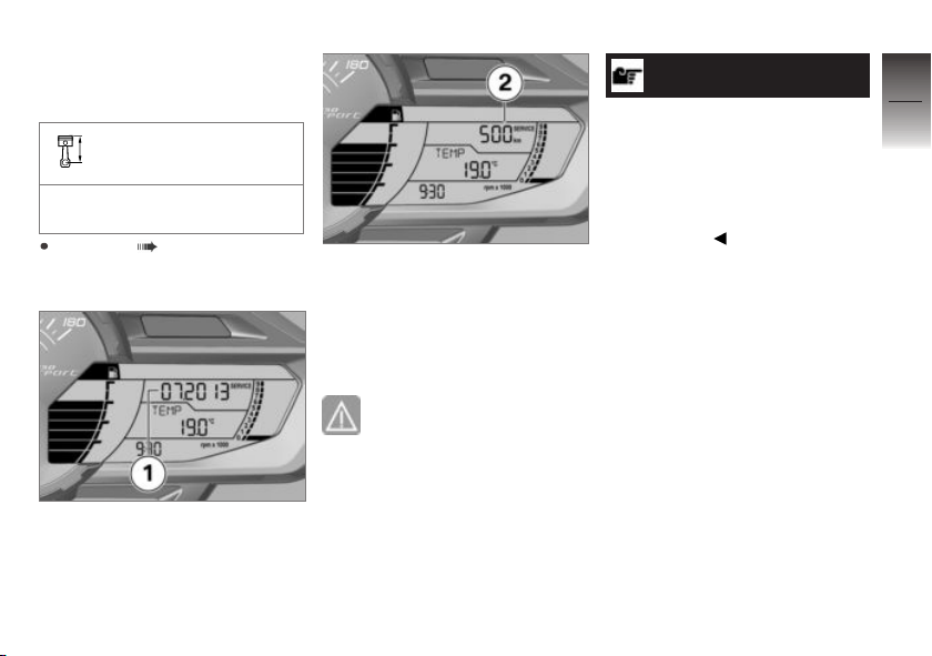
Service display
If service is due within a month,
the service date 1 is displayed.
If service is due within 700 miles,
the remaining distance 2 is displayed and is counted down in
steps of 100 miles. It is briefly
displayed following the Pre-RideCheck.
When a service date
elapses without service,
the general warning light
lights up in yellow, appearing
together with the date and
mileage (kilometerage) display.
The SERVICE message is
displayed continuously.
NOTICE
If the service display appears
more than a month before the
service date, the current day's
date must be reset in the instrument cluster. This situation can occur if the battery was
disconnected.
3
37
z
Displays
Page 40
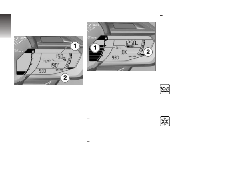
Distance traveled since
3
fuel reached reserve
level
38
z
Displays
The distance traveled 1 since
reaching the fuel reserve is displayed by the symbol 2. This
odometer is reset and no longer
displayed once the fuel reserve
quantity is exceeded.
Oil level indicator
The oil level display 1 provides
information on the oil level in the
engine. This display can only
be activated when the vehicle is
stopped.
The conditions required for using
the oil level display are as follows:
Engine at normal operating
temperature.
Engine idling for at least ten
seconds.
Side stand retracted.
Maxi-Scooter is positioned vertically.
The displays which may appear
in positions 1 and 2 mean the
following:
OIL OK: Oil level correct.
OIL CHECK: Check oil level
during next refueling stop.
OIL ---: No measurement
possible (above-mentioned conditions not met).
If the oil level is too low,
the corresponding warning
symbol is displayed.
Outside temperature
When the outside temper-
ature drops below 37 °F
(3 °C) the temperature display
responds by flashing a warning
indicating possible ice formation
on the road surface. The display
automatically switches from any
other mode to the temperature
Page 41
reading when the temperature
drops below this threshold for
the first time.
Tire inflation pressures
with Tire Pressure Control
(TPC/RDC)
OE
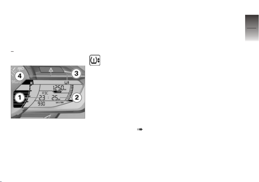
ter switching on the ignition,
--:-- is displayed, as the
transmission of the tire pressure values does not begin until
a speed of 19 mph (30 km/h) is
exceeded for the first time.
If the general warning
light 4 flashes red and if
the symbol 3 is also displayed,
then a warning indicator is
concerned. The upper arrow
next to the tire symbol indicates
a problem at the front wheel,
and the lower arrow indicates a
problem at the rear wheel.
3
39
z
Displays
The displayed tire inflation pressures refer to a tire air temperature of 68 °F (20 °C). The figure on the left side 1 indicates
the front tire's inflation pressure,
while the figure on the right 2
shows the inflation pressure in
the rear tire. Immediately af-
Further information on
BMW Motorrad TPC/RDC can
be found from page ( 79)
onwards.
Page 42

3
40
z
Displays
Page 43

Operation
Steering and ignition lock . . . . . . . . . . . 42
Emergency on/off switch (kill
switch) . . . . . . . . . . . . . . . . . . . . . . . . . . . . . . 43
Lights . . . . . . . . . . . . . . . . . . . . . . . . . . . . . . . 43
Hazard warning lights system . . . . . . . 44
Turn indicators . . . . . . . . . . . . . . . . . . . . . . 45
Display . . . . . . . . . . . . . . . . . . . . . . . . . . . . . . 45
SETUP . . . . . . . . . . . . . . . . . . . . . . . . . . . . . 47
Time and date . . . . . . . . . . . . . . . . . . . . . . 48
Automatic Stability Control
(ASC) . . . . . . . . . . . . . . . . . . . . . . . . . . . . . . . 50
Anti-theft alarm (DWA) . . . . . . . . . . . . . . 52
Heated handlebar grips . . . . . . . . . . . . . 54
Seat heating . . . . . . . . . . . . . . . . . . . . . . . . 54
Seat . . . . . . . . . . . . . . . . . . . . . . . . . . . . . . . . 56
Tank cover. . . . . . . . . . . . . . . . . . . . . . . . . . 56
Storage compartments . . . . . . . . . . . . . 57
4
41
z
Operation
Page 44
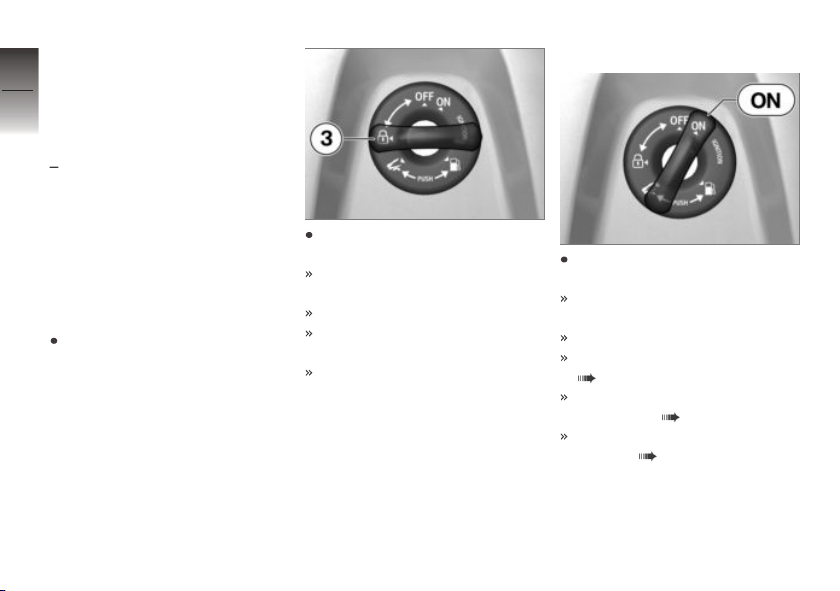
Steering and ignition
4
lock
42
Ignition key
You receive two ignition keys.
with Topcase
The Topcase can also be operated using the same ignition
key if desired. Please contact an
authorized workshop for this purpose, preferably an authorized
z
Operation
BMW Motorrad retailer.
Locking handlebars
Turn handlebars to left.
OA
Turn key to position 3 while
moving handlebars slightly.
Ignition, lights and all electrical
circuits are switched off.
Handlebars are locked.
Left-hand storage compartment is locked.
Key can now be removed.
Switching on ignition
Turn the ignition key to the ON
position.
Parking lights and all function
circuits switched on.
Engine can be started.
Pre-Ride-Check is carried out.
( 66)
ABS self-diagnosis is
performed. ( 67)
ASC self-diagnosis is performed. ( 68)
Page 45
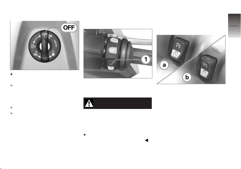
Switch off ignition
Turn the ignition key to
the OFF position.
Light is switched off, parking
lamps and lighting for the rear
storage compartment stay lit
up for a little while.
Handlebars not locked.
Key can now be removed.
Emergency on/off switch (kill switch)
1 Emergency on/off switch
(kill switch)
WARNING
Operation of the emergency
ON/OFF switch when riding
Danger of falling due to blocking
of rear wheel
Do not operate the emergency
ON/OFF switch when riding.
The engine can be switched
off easily and quickly using the
emergency on/off switch.
a Engine is switched off
b Operating position
Lights
Low-beam headlight and
parking lights
The parking lights come on automatically when the ignition is
switched on.
After switching off the ignition,
the parking lamps remain lit for a
short time.
4
43
z
Operation
Page 46
4
44
z
Operation
NOTICE
The parking lights are a strain
on the battery. Do not leave the
ignition switched on longer than
absolutely necessary.
The low-beam headlight switches
on automatically when the engine
is switched on.
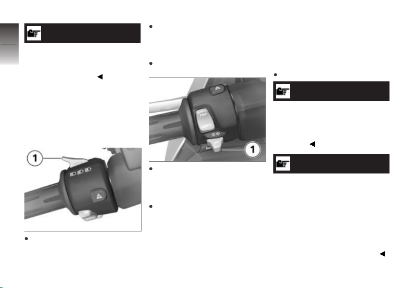
High-beam headlight and
headlight flasher
Pull switch 1 toward rear to
actuate headlight flasher.
Parking lights
Switch off ignition.
Hazard warning lights system
Operate hazard warning
flashers
Switch on the ignition.
NOTICE
The hazard warning flashers
place a strain on the battery.
Do not use the hazard warning
flashers for longer than absolutely
necessary.
Press switch 1 toward front to
switch on high-beam headlight.
Immediately after switching off
ignition, push button 1 to left
and hold it until parking lights
come on.
Switch ignition on and then off
again to switch off parking light.
NOTICE
If a turn indicator button is
pressed with the emergency
flashing function switched on,
the flashing function replaces the
emergency flashing function as
long as the button is pressed.
If the turn indicator button is
released, the emergency flasher
function becomes active again.
Page 47
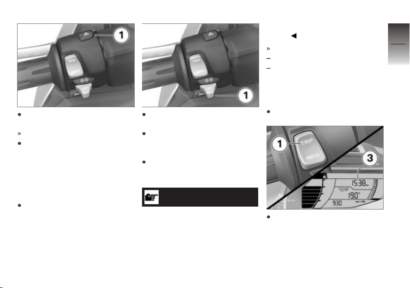
Press button 1 to switch on
hazard warning flashers.
Ignition can be switched off.
Switch on ignition and press
button 1 again to switch off
hazard warning flashers.
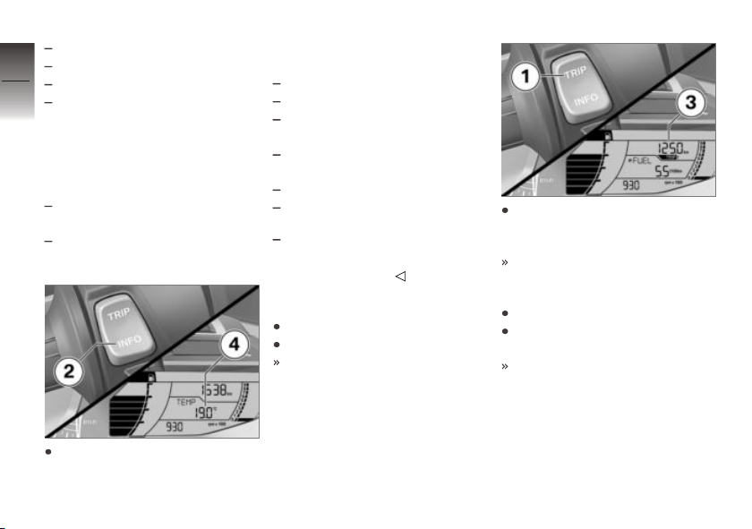
Turn indicators
Operating turn indicators
Switch on the ignition.
Press button 1 to left to switch
on left-side turn indicators.
Press button 1 to right to
switch on right-side turn
indicators.
Press button 1 into center position to switch off turn indicators.
NOTICE
The turn indicators automatically switch off when the defined
driving time and distance have
been reached. The defined riding time and distance can be set
by an authorized BMW Motorrad
retailer.
Factory setting:
Riding time = 10 s
Distance = 200 m
Display
Selecting display readings
Switch on the ignition.
Briefly press TRIP 1 in each
case to select the display in
section 3.
The following data can be displayed:
4
45
z
Operation
Page 48
Odometer
Trip odometer 1 TRIP 1
4
Trip odometer 2 TRIP 2
46
The automatic trip distance
TRIP A is automatically re-
set if at least five hours have
passed since the ignition was
switched off and the date has
changed.
Fuel reserve reached: Distance
traveled since this point in time
Call up the settings menu:
z
Operation
SETUP
Briefly press INFO 2 in each
case to select the display in
section 4.
The following data can be displayed:
Ambient temperature TEMP
Average speed ØSPEED
Average fuel consumption
ØFUEL
Current fuel consumption
FUEL
Date DATE
Oil level indicator OIL
with Tire Pressure Control
(TPC/RDC)
OE
RDC tire pressures
Resetting trip odometer
Switch on the ignition.
Select tripmeter.
The desired trip odometer is
displayed.
Hold down TRIP 1 until the
trip odometer 3 has been reset.
Trip mileage = 0.0
Resetting average data
Switch on the ignition.
Select average fuel consumption or average speed.
The desired average value is
displayed.
Page 49
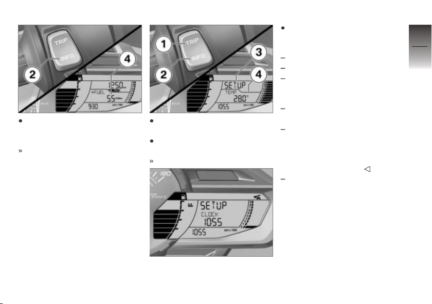
Hold down INFO 2 until the
displayed average value 4 resets.
Average value = 0.0
SETUP
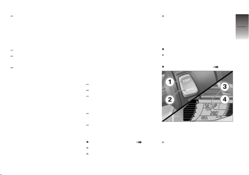
Selecting the SETUP
Requirement
The Maxi-Scooter is stationary.
Requirement
The onboard computer is displayed.
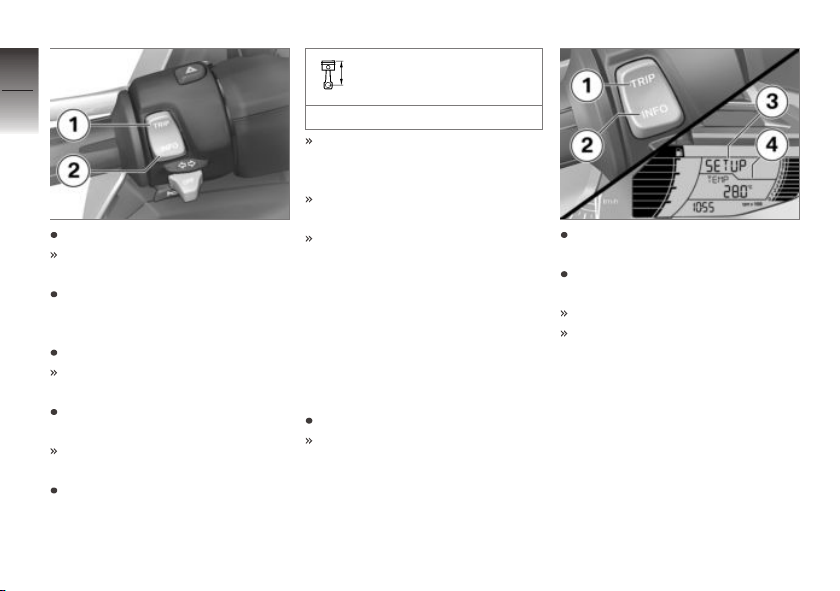
Briefly press TRIP 1 repeatedly
until SETUP 3 is displayed.
Press and hold TRIP 1 to start
SETUP.
The dividing line 4 is hidden.
SETUP CLOCK is displayed.
Briefly press TRIP 1 in each
case to select the following
parameter in SETUP.
Set time display CLOCK.
Set the date DATE.
Switch ASC on or off ASC
ON / ASC OFF; or calibrate
ASC ASC CAL.
with anti-theft alarm system
OE
(DWA)
Automatically activate the alarm
function of the anti-theft alarm
system after switching off the
ignition DWA ON or leave de-
activated DWA OFF.
Exit SETUP EXIT.
Exit SETUP
Requirement
There are four ways to exit
SETUP.
4
47
z
Operation
Page 50
4
48
Press and hold TRIP 1.
The on-board computer is displayed.
z
Operation
Alternatively: Briefly press
TRIP 1 repeatedly until
SETUP EXIT is displayed.
Press and hold INFO 2.
The on-board computer is displayed.
Alternate method: Switch the
ignition off and then on.
The on-board computer is displayed.
Alternatively: Drive off.
Speed for the operation
is in SETUP
max 6 mph (max 10 km/h)
When the permissible speed
for operation is exceeded,
SETUP ends.
The on-board computer is displayed.
All settings are saved irrespective of how SETUP was
closed.
Time and date
Set clock
Requirement
The Maxi-Scooter is stationary.
Switch on the ignition.
The onboard computer is displayed.
Briefly press TRIP 1 repeatedly
until SETUP 3 is displayed.
Press and hold TRIP 1 to start
SETUP.
The dividing line 4 is hidden.
SETUP CLOCK is displayed.
Page 51

Press and hold INFO 2 to set
the hours.
Hours 7 flash.
Briefly press TRIP 1 to increase hours.
Briefly press INFO 2 to reduce
hours.
When the hours have been
set as desired, press and hold
INFO 2.
Minutes 6 flash.
Briefly press TRIP 1 to increase minutes.
Briefly press INFO 2 to reduce
minutes.
When the minutes have been
set as desired, press and hold
INFO 2.
The minutes 6 no longer flash.
Check the setting on the time
display 8.
The clock is now set.
Press and hold TRIP 1.
The on-board computer is displayed.
Set date
Requirement
The Maxi-Scooter is stationary.
Switch on the ignition.
The onboard computer is displayed.
Selecting the SETUP ( 47).
SETUP 3 is started. The dividing
line 4 is hidden.
SETUP DATE is displayed.
Press and hold INFO 2.
The year 6 flashes.
4
49
z
Operation
Page 52
Briefly press TRIP 1 to move
the year forwards.
4
Briefly press INFO 2 to move
50
the year backwards.
When the year has been set
as desired, press and hold
INFO 2.
The month 8 flashes.
Briefly press TRIP 1 to move
the month forwards.
Briefly press INFO 2 to move
the month backwards.
z
Operation
When the month has been
set as desired, press and hold
INFO 2.
The day 7 flashes.
Briefly press TRIP 1 to move
the day forwards.
Briefly press INFO 2 to move
the day backwards.
When the day has been set
as desired, press and hold
INFO 2.
The day 7 no longer flashes.
The clock is now set.
Press and hold TRIP 1.
The on-board computer is displayed.
Automatic Stability Control (ASC)
Deactivating ASC
Requirement
The Maxi-Scooter is stationary.
Switch on the ignition.
The onboard computer is displayed.
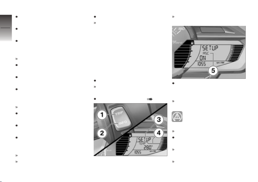
Selecting the SETUP ( 47).
SETUP 3 is started. The dividing
line 4 is hidden.
SETUP ASC is displayed.
Briefly press INFO 2 to switch
between 5 ASC ON 5 and
ASC OFF.
SETUP ASC OFF is dis-
played.
ASC warning light lights up.
ASC is switched off.
Press and hold TRIP 1 to exit
SETUP.
The onboard computer is displayed.
Even with ASC switched off,
engine speed is governed to
Page 53
prevent extreme acceleration
of the rear wheel while clear of
the ground. This is in order to
protect the drive train.
Switch on ASC
Requirement
The Maxi-Scooter is stationary.
Switch on the ignition.
The onboard computer is displayed.
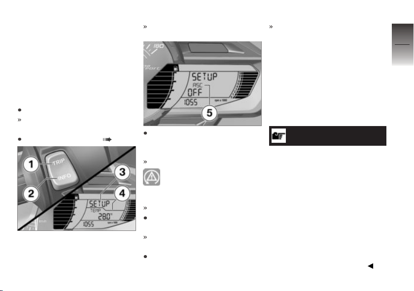
Selecting the SETUP ( 47).
SETUP 3 is started. The dividing
line 4 is hidden.
SETUP ASC is displayed.
Briefly press INFO 2 to switch
between 5 ASC ON and
ASC OFF 5.
SETUP ASC ON is displayed.
ASC warning light stays
out or flashes until the self-
diagnosis is completed.
ASC is switched on.
Press and hold TRIP 1 to exit
SETUP.
The onboard computer is displayed.
Alternatively, switch the ignition
off and on again.
If the ASC warning light con-
tinues to light up after switch-
ing the ignition off and then
on again, an ASC fault has oc-
curred.
Calibrating ASC
Requirement
Reduced stability reserves of the
ASC control after tire change.
NOTICE
Calibrating means that the control is adapted to the effective
tire radii of the front and rear
wheel.
The effective tire radius depends
on the tire make, tread depth, tire
pressure and load.
Calibrate the ASC control after
every tire change to compensate
for changes in the tire radii.
Calibrate the ASC control regularly as tire wear progresses to
maintain optimum operation.
4
51
z
Operation
Page 54
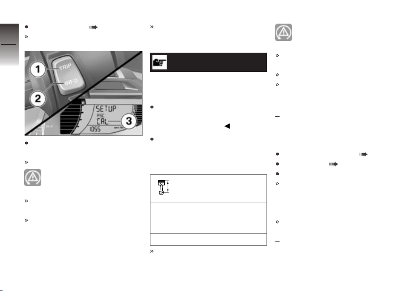
Switch on ASC ( 51).
SETUP ASC ON is displayed.
4
52
z
Operation
Press and hold INFO 2 to start
calibration.
CAL. 3 flashes.
ASC warning light begins to
light up.
TRIP 1 and INFO 2 have no
function.
The menu item can only be
closed by switching the ignition
off and on.
Calibration starts up and waits
for the MaxiScooter to be
driven.
ATTENTION
ASC is not available until
calibration is completed
Accident hazard
Carry out calibration on a flat
and straight stretch of road that
has good adhesion.
Travel straight ahead and keep
the speed constant within
the following speed range for
6 seconds.
Speed range for ASC
calibration
The MaxiScooter must be
driven straight ahead in a specific speed range:
19...31 mph (30...50 km/h)
ASC is calibrated.
ASC warning light goes out.
The onboard computer is displayed.
ASC calibration is completed.
You may continue driving.
Anti-theft alarm (DWA)
with anti-theft alarm system
OE
(DWA)
Activate DWA
Switching on ignition ( 42).
Adjust DWA ( 53).
Switch off ignition.
If the DWA is activated, the
DWA is automatically activated
after the ignition is switched
off.
Activation takes approximately
30 seconds to complete.
Turn indicators are illuminated
twice.
Page 55
Confirmation tone sounds
twice (if programmed).
Alarm signal
The DWA alarm can be set off
by:
Motion sensor
Switching on ignition with an
unauthorized motorcycle key.
Disconnecting the DWA from
the motorcycle battery (DWA
battery takes over the power
supply – alarm sound only, hazard warning lights do not flash).
If the DWA battery is discharged
all functions remain operational;
the only difference is that the
alarm cannot be set off if the
system is disconnected from the
motorcycle battery.
The duration of the alarm signal is approx. 26 seconds. During the DWA alarm, an alarm
tone sounds and the indicators flash. The type of alarm
sound can be set by an authorized BMW Motorrad retailer.
If a DWA alarm was activated
while the motorcycle was
unattended, the driver is notified
accordingly by an alarm tone
sounding once when the ignition
is switched on. The DWA LED
then indicates the reason for the
DWA alarm for one minute.
Light signals on DWA LED:
1 flash: Motion sensor 1
2 flashes: Motion sensor 2
3 flashes: Ignition switched on
with unauthorized motorcycle
key
4 flashes: DWA disconnected
from motorcycle battery
5 flashes: motion sensor 3
Deactivate DWA
Switching on ignition ( 42).
Turn indicators light up once.
Confirmation tone sounds once
(if programmed).
DWA is now switched off.
Adjust DWA
Requirement
The Maxi-Scooter is stationary.
Switch on the ignition.
The onboard computer is displayed.
Selecting the SETUP ( 47).
SETUP 3 is started. The dividing
line 4 is hidden.
SETUP DWA is displayed.
4
53
z
Operation
Page 56
4
54
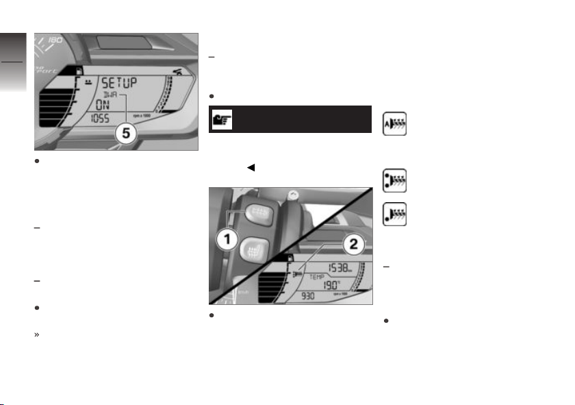
Briefly press INFO 2 to switch
between DWA ON 5 and
DWA OFF.
z
Operation
The following settings are available:
DWA ON: DWA is activated
respectively is activated automatically when the ignition is
switched off.
DWA OFF: DWA is deacti-
vated.
Press and hold TRIP 1 to exit
SETUP.
The onboard computer is displayed.
Heated handlebar grips
with heated handlebar grips
Operating heated grips
Start engine.
NOTICE
The heated grips option can only
be activated when the engine is
running.
Press button 1 repeatedly until desired heating level 2 is
shown.
The handlebar grips can be
heated manually at two levels
OE
or automatically. The second
manual level is used for fast
heat-up of the grips; then the
switch should be switched back
to the first level. The following
displays are available:
Heater output is automat-
ically adjusted in dependence on ambient temperature,
speed and engine speed.
100 % heating output
Approx. 50 % heater out-
put
Seat heating
with seat heating
Operating driver's seat
heater
Start engine.
OE
Page 57
NOTICE
Seat heating can be activated
only when the engine is
running.
The following displays are available:
Heater output is automat-
ically adjusted in dependence on ambient temperature,
speed and engine speed.
100 % heating output
4
55
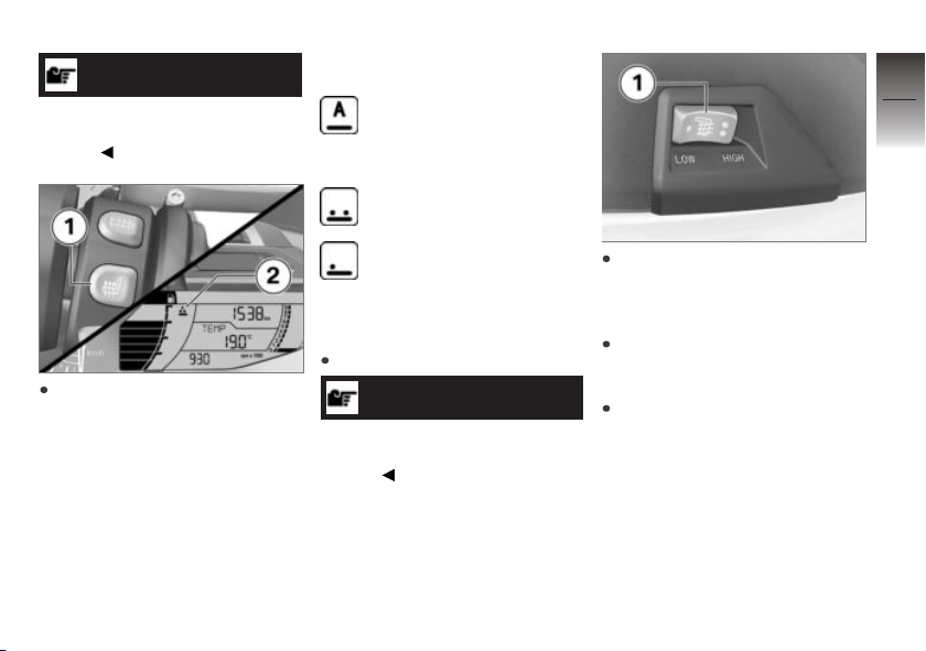
Press button 1 repeatedly until desired heating level 2 is
shown.
The rider`s seat can be heated
at two manual levels or automatically. The second manual level
is used for fast heat-up of the
seat; then the switch should be
switched back to the first level.
Approx. 50 % heater output
Operating passenger seat
heater
Start engine.
NOTICE
Seat heating can be activated
only when the engine is
running.
Operate the rocker switch 1
on the side with two dots, to
switch on the high heater output HIGH.
Operate the rocker switch 1 on
the side with one dot, to switch
on the low heater output LOW.
Set the rocker switch 1 to the
center position, to switch off
seat heating.
z
Operation
Page 58
4
56
Seat
Operating seat
Switch off ignition.
The set level 2 is shown in the
display. The second stage is
used to quickly heat up the pas-
z
Operation
senger seat; then the switch
should be switched back to the
first stage. The following displays
are available:
Approx. 50 % heater output
100 % heating output
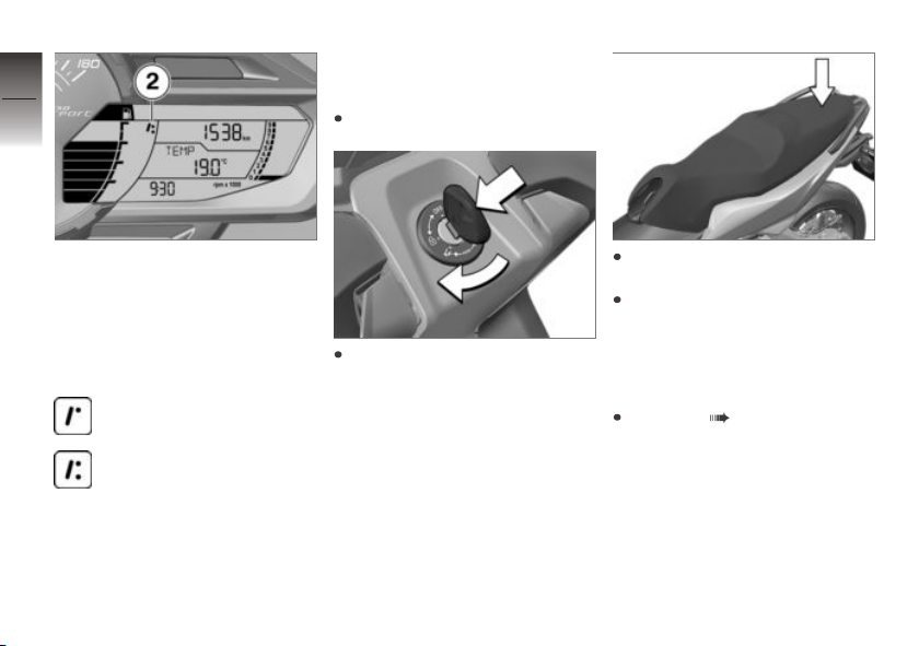
Insert the ignition key into the
steering lock and then turn it
clockwise.
If seat is jammed, press down
at rear and then raise at rear.
To close, press seat into locking device at rear.
Tank cover
Unlocking the tank cover
Refueling ( 71).
Page 59
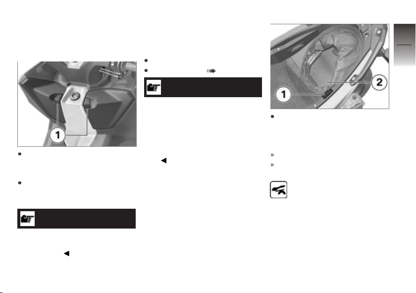
Storage compartments
Operating front storage
compartments
To open a storage compart-
ment, pull corresponding re-
lease lever 1 downward.
To close a storage compart-
ment, press corresponding
door into locking device.
NOTICE
The left-hand storage compartment is locked together with the
steering lock.
Operating rear storage
compartment (BMW
Flexcase)
Open seat.
Operating seat ( 56).
NOTICE
The lighting of the storage compartment is switched on when
the ignition is switched on.
After switching off the ignition,
the storage compartment remains illuminated for a short
time.
Pull release lever 1 toward
front to enlarge storage compartment, e.g. for holding motorcycle helmets.
The bottom 2 lowers.
The vehicle cannot be started
with the bottom lowered.
If the ignition is switched
on, the storage compart-
ment symbol is displayed.
4
57
z
Operation
Page 60
4
58
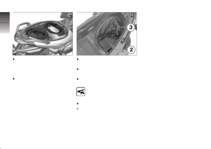
To store two helmets in the
storage compartment, position
the helmets as shown in the
z
Operation
picture.
Close seat.
To continue the journey, open
the seat bench.
Emptying the storage compartment
Pull the floor upwards 2 using
the lever 3 into the lock.
If the ignition is switched
on, the storage compart-
ment symbol is hidden.
Close seat.
You may continue driving.
Page 61

Setting
Mirrors . . . . . . . . . . . . . . . . . . . . . . . . . . . . . . 60
Headlight . . . . . . . . . . . . . . . . . . . . . . . . . . . 60
Windshield . . . . . . . . . . . . . . . . . . . . . . . . . . 60
Brakes . . . . . . . . . . . . . . . . . . . . . . . . . . . . . . 61
Spring preload . . . . . . . . . . . . . . . . . . . . . . 61
5
59
z
Setting
Page 62
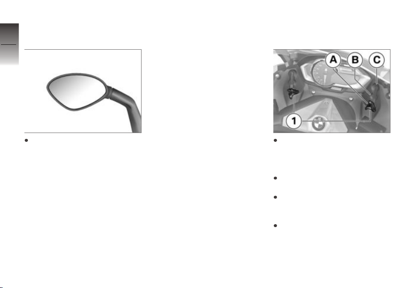
Mirrors
5
Adjusting mirrors
60
z
Setting
Move mirror into desired position by applying light pressure
at edge.
Headlight
Adjusting headlight for
RHD/LHD traffic
This motorcycle's headlight fea-
tures a symmetrical low beam.
No special adjustments or proce-
dures are required prior to oper-
ating the motorcycle in a coun-
try where traffic travels on the
side of the road opposite to that
of your home country (left-hand
drive to right-hand drive or vice
versa).
Headlight range and
spring preload
The headlight range generally
remains constant due to the adjustment of the spring preload to
the loading state.
If you are unsure whether the
headlight range is correct,
consult a specialized workshop,
preferably an authorized
BMW Motorrad retailer.
Windshield
Adjusting windshield
Loosen the left and right
clamping bolts 1 until the
windshield can be easily
adjusted.
Move windshield into desired
position A, B or C.
Make sure that the windshield
is adjusted identically on the
left and right.
Tighten clamping screws on
left and right.
Page 63
Brakes
Adjust handbrake lever
WARNING
Modified position of the
brake fluid reservoir
Air in the brake system
Do not twist the handlebar fit-
ting or the handlebars.
WARNING
Adjusting the handbrake
lever while driving.
Accident hazard
Only adjust the handbrake
lever when the Scooter is
stationary.
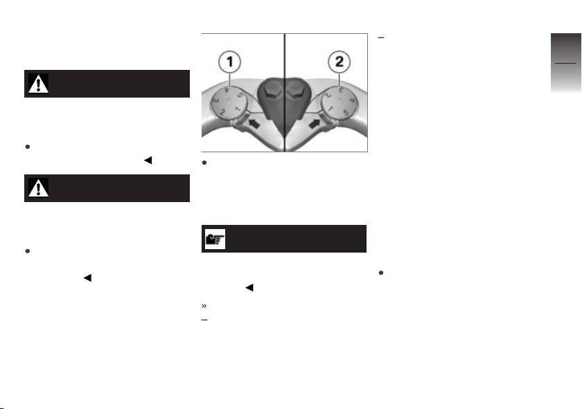
Turn adjusting screw 1 of the
left handbrake lever or adjusting screw 2 of the right handbrake lever into the desired
position.
NOTICE
The adjusting screw is easier to
turn if you push the brake lever
forwards.
Adjustment options:
from Position 1: largest distance between handlebar grip
and brake lever
up to Position 5: smallest distance between handlebar grip
and brake lever
Spring preload
Setting
It is essential to set spring
preload of the rear suspension
to suit the load carried by the
MaxiScooter. Increase spring
preload when the vehicle is
heavily loaded and reduce spring
preload accordingly when the
vehicle is lightly loaded.
Adjusting spring preload
at rear wheel
Make sure ground is level and
firm and place Maxi-Scooter on
its center stand.
5
61
z
Setting
Page 64
5
62
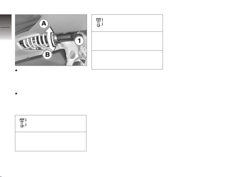
If you want to increase the
z
Setting
spring preload, turn adjusting
ring 1 with the tools from the
onboard toolkit in direction A.
If you want to decrease the
spring preload, turn adjusting
ring 1 with the tools from the
onboard toolkit in direction B.
Basic setting of spring
preload, rear
Increase from lowest preload
by 3 notches. (One-up without
load)
Basic setting of spring
preload, rear
Increase from lowest preload
by 4 notches. (One-up with
load)
Increase from lowest preload
by 6 notches. (Two-up and
load)
Page 65

Riding
Safety instructions . . . . . . . . . . . . . . . . . . 64
Observe checklist . . . . . . . . . . . . . . . . . . . 66
Starting . . . . . . . . . . . . . . . . . . . . . . . . . . . . . 66
Riding. . . . . . . . . . . . . . . . . . . . . . . . . . . . . . . 68
Running in . . . . . . . . . . . . . . . . . . . . . . . . . . 69
Brakes . . . . . . . . . . . . . . . . . . . . . . . . . . . . . . 69
Maxi-Scooter Parking . . . . . . . . . . . . . . . 70
Refueling . . . . . . . . . . . . . . . . . . . . . . . . . . . 71
Secure motorcycle for transport . . . . 73
6
63
z
Riding
Page 66
Safety instructions
6
Rider's Equipment
64
Do not drive without the correct
clothing:
Helmet
Rider's suit
Gloves
Boots
This applies even to short
z
Riding
journeys, and to every season
of the year. Your authorized
BMW Motorrad retailer will be
happy to advise you and has
the correct clothing for every
purpose.
Load
WARNING
Reduced riding stability
caused by overloading and
uneven loading
Accident hazard
Do not exceed the gross
weight limit and observe the
loading information.
Adjust the spring preload setting to the total weight of the
vehicle.
with luggage carrier
Comply with maximum payload
of luggage rack.
Payload of luggage rack
max 20 lbs (max 9 kg)
with Topcase
Observe maximum payload and
permissible top speed of Topcase.
Topcase payload
max 11 lbs (max 5 kg)
OA
OA
Maximum speed limit for
driving with a Topcase
max 112 mph (max
180 km/h)
Speed
If you drive at high speed, always
bear in mind the following examples of marginal conditions that
can adversely affect the drivability
of your Maxi-Scooter:
Setting for the suspension system
Unevenly distributed load
Loose clothing
Insufficient tire inflation pressure
Tire tread in poor condition
Risk of poisoning
Exhaust fumes contain carbon
monoxide, which is colorless and
odorless but highly toxic.
Page 67
WARNING
Harmful exhaust gas
Danger of suffocation
Do not inhale exhaust fumes.
Do not run the engine in
closed rooms.
Burn hazard
CAUTION
Intense heating up of engine
and exhaust system while
riding
Burn hazard
After parking the motorcycle,
make sure that no persons
or objects come into contact
with the engine and exhaust
system.
Catalytic converter
If misfiring causes unburned fuel
to enter the catalytic converter,
there is a danger of overheating
and damage.
The following must be observed:
Do not run the fuel tank dry.
Do not run the engine with the
spark-plug cap removed.
Stop the engine immediately if
it misfires.
Use unleaded fuel only.
Comply with all specified maintenance intervals.
ATTENTION
Unburned fuel in the catalytic
converter
Damage to catalytic converter
Note the points listed for
protection of the catalytic
converter.
Danger of overheating
ATTENTION
Engine idling for a lengthy
period while at a standstill
Overheating due to insufficient
cooling; in extreme cases vehicle
fire
Do not allow the engine to idle
unnecessarily.
After starting, ride off
immediately.
Modifications
ATTENTION
Modifications to the MaxiScooter (e.g., engine control
unit, throttle valves, clutch)
Damage to the affected parts,
failure of safety-relevant functions. Damage caused in this
way is not covered by the warranty.
6
65
z
Riding
Page 68
Do not make any
modifications.
6
66
Observe checklist
Use the following checklist to
check your motorcycle at regular intervals.
Requirement
Before every journey:
z
Riding
Check operation of the brake
system.
Check operation of the lighting
and signal system.
Check tire tread depth ( 93).
Check secure hold of topcase
and luggage.
Requirement
At every third refuelling stop:
Adjusting spring preload at rear
wheel ( 61).
Check engine oil level ( 84).
Check front brake pad thickness ( 87).
Checking rear brake pad thickness ( 87).
Checking brake fluid level of
front brake ( 89).
Checking brake fluid level for
rear brake ( 90).
Checking coolant level ( 91).
Starting
Starting engine
Switch on the ignition.
Pre-Ride-Check is carried out.
( 66)
ABS self-diagnosis is
performed. ( 67)
ASC self-diagnosis is performed. ( 68)
Operate brake.
NOTICE
Vehicle cannot be started with
side stand extended. If side
stand is extended with engine
running, engine stops.
Press starter button 1.
Engine starts.
Consult the troubleshooting
chart if the engine refuses to
start. ( 128)
Pre-Ride-Check
After the ignition is switched on,
the instrument cluster conducts a
test of the analog instruments as
well as the warning and indicator lights in a "Pre-Ride-Check".
Starting the engine before the
test routine is completed will
Page 69

cancel the remainder of the routine.
Phase 1
The pointer of the speedometer
is run up to the end stop. The
warning and indicator lights are
switched on.
Phase 2
The speedometer pointer is
moved back. The switched-on
indicator and warning lights are
switched off.
If the pointer has not been
moved, or if one of the warning
and indicator lights has not been
switched on:
WARNING
Defective warning lights
Lack of display of malfunctions
Check the display of all indica-
tor and warning lights.
Have the malfunction corrected
as soon as possible at an
authorized service facility,
preferably an authorized
BMW Motorrad Retailer.
ABS self-diagnosis
The self-diagnosis routine
is determining whether
BMW Motorrad ABS is ready for
operation. The self-diagnosis
routine runs automatically when
you switch on the ignition. To
check the wheel speed sensors,
the Maxi-Scooter must be driven
a few meters.
Phase 1
Check on system components
monitored by diagnostic system while motorcycle is parked.
ABS warning lamp flashes.
Phase 2
Check wheel sensors while
starting off.
ABS warning lamp flashes.
ABS self-diagnosis
completed
ABS warning light goes out.
If an ABS error is displayed after
the ABS self-diagnosis is completed:
It remains possible to continue
riding. It must be noted that
the ABS function is not available.
Have the malfunction corrected
as soon as possible at an
authorized service facility,
preferably an authorized
BMW Motorrad Retailer.
6
67
z
Riding
Page 70
ASC self-diagnosis
6
The self-diagnosis routine
is determining whether
68
BMW Motorrad ASC is ready for
operation. The self-diagnosis
routine runs automatically when
you switch on the ignition.
Phase 1
Check on system components
z
Riding
monitored by diagnostic system while motorcycle is parked.
ASC warning light flashes
slowly.
Phase 2
Checks diagnosis-capable system components when motorcycle starts to move.
ASC warning light flashes
slowly.
ASC self-diagnosis
completed
The ASC symbol is no longer
displayed.
Watch all warning and indicator
lights on the display.
ASC self-diagnosis routine not completed
The MaxiScooter must reach
a specified minimum speed
with the engine running before
the system can check operation of the wheel speed sensors:
min 3 mph (min 5 km/h)
If an ASC error is displayed after
the ASC self-diagnosis is completed:
It remains possible to continue
riding. It must be noted that
the ASC function is not available.
Have the malfunction corrected
as soon as possible at an
authorized service facility,
preferably an authorized
BMW Motorrad Retailer.
If the ASC adjusts without request, too often or too soon,
refer to the troubleshooting table for help. ( 128)
Riding
At engine speeds below approximately 1800 rpm, the centrifugal clutch opens and the MaxiScooter is idling. If the engine
speed is increased, the clutch
closes and the Maxi-Scooter
drives off.
In the range from approximately
25 mph (40 km/h) to approximately 75 mph (120 km/h), the
engine operates at almost constant speed in the range of the
maximum torque. The change in
speed is achieved by CVT. This
only slightly changes the engine
noise in this speed range.
Speeds above approximately
75 mph (120 km/h) are achieved
by increasing the engine speed.
Page 71

Running in
Engine
Drive in frequently changing
load ranges prior to the pre-
delivery check.
Try to do most of your rid-
ing during this initial period on
twisting, fairly hilly roads, avoid-
ing highways if possible.
Have the initial inspection per-
formed after the first 300 -
750 mls (500 - 1200 km).
Brake pads
New brake pads must be run in
before they achieve their optimum friction force. This initial
reduction in braking efficiency
can be compensated for by exerting greater pressure on the
brake levers.
WARNING
New brake pads
Extension of the braking distance,
accident hazard
Brake early.
Tires
New tires have a smooth surface. This must be roughened by
riding in a restrained manner at
various heel angles until the tires
are run in. This running in procedure is essential if the tires are to
achieve maximum grip.
WARNING
Loss of adhesion of new tires
on wet roads and at extreme
angles
Accident hazard
Always think well ahead and
avoid extreme angles.
Brakes
How do you achieve
the shortest stopping
distances?
During braking the load distribution changes dynamically between the front and the rear
wheel. The heavier you brake,
the greater the weight transfer
to the front wheel. Increases in
the load on an individual wheel
are accompanied by a rise in the
effective braking force that the
wheel can provide.
To achieve the shortest possible braking distance, the front
brake must be applied quickly
and with progressively greater
levels of force. This procedure
provides ideal exploitation of
the extra weight transfer to the
front wheel. With the frequently
instructed "forced braking," in
which the brake pressure is generated as quickly as possible and
6
69
z
Riding
Page 72
with great force, dynamic load
distribution lags behind the pro-
6
gressive increases in deceleration
70
rate and the braking force cannot
be completely transferred to the
road surface. It would cause the
front wheel to lock up.
Locking up of the front wheel
is prevented by BMW Motorrad
ABS.
z
Riding
Descending mountain
passes
WARNING
Braking only with the rear-
wheel brake when descend-
ing mountain passes
Reduced of braking action, de-
struction of the brakes caused by
overheating
Use both front and rear brakes,
and make use of the engine's
braking effect as well.
Wet, soiled brakes
Moisture and dirt on the brake
disks and the brake pads result in
a decrease in the braking action.
Delayed or poorer braking action
must be expected in the following situations:
When driving in the rain and
through puddles.
After washing the vehicle.
When driving on roads spread
with salt.
After working on the brakes
due to oil or grease residues.
When driving on soiled roads
or offroad.
WARNING
Poorer braking action due to
moisture and dirt
Accident hazard
Brake until brakes are dry or
clean; clean if necessary.
Brake early until the full braking
action is available again.
Maxi-Scooter Parking
Side stand
Switch off engine.
ATTENTION
Poor ground conditions in
area of stand
Component damage cause by
tipping over
Always check that the ground
under the stand is level and
firm.
Extend side stand and park
Maxi-Scooter.
The parking brake prevents the
motorcycle from rolling.
ATTENTION
Loading of the side stand
with additional weight
Page 73
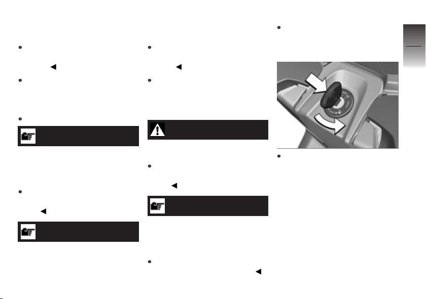
Component damage cause by
tipping over
Do not sit on the motorcycle
when it is parked on the side
stands.
If the slope of the road permits,
turn the handlebars to the left.
Component damage cause by
tipping over
Do not sit on the motorcycle
while it is resting on the center
stand.
Extend center stand and jack
up Maxi-Scooter.
Make sure ground is level and
firm and place Maxi-Scooter on
its center stand.
6
71
Center stand
Switch off engine.
ATTENTION
Poor ground conditions in
area of stand
Component damage cause by
tipping over
Always check that the ground
under the stand is level and
firm.
ATTENTION
Center stand folds if subject
to sharp movements.
Refueling
WARNING
Fuel is highly flammable
Fire and explosion hazard
Do not smoke. Never bring
a naked flame near the fuel
tank.
ATTENTION
Contact of fuel and plastic
surfaces
Damage to surfaces (become
unattractive or cloudy)
Immediately clean plastic surfaces after contact with fuel.
Push the ignition key into the
center position of the steering
lock and then turn it counterclockwise.
z
Riding
Page 74
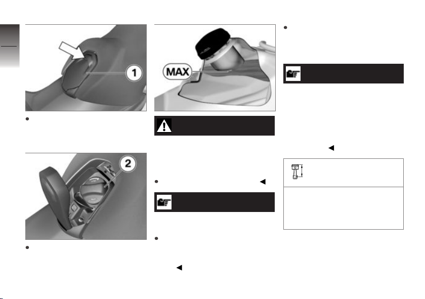
6
72
In case of jamming, press tank
z
Riding
cover 1 toward rear and then
fold open toward front.
Open the fuel filler cap 2.
WARNING
Escaping of fuel due to expansion under exposure to
heat with overfilled fuel tank
Accident hazard
Do not overfill the fuel tank.
ATTENTION
Refueling with leaded fuel
Damage to catalytic converter
Do not refuel with leaded gasoline or gasoline with metallic
additives, e.g. manganese or
iron.
Refuel with a fuel of the quality specified, continuing until
fuel is no higher than the lower
edge of the filler neck.
NOTICE
If refueling is carried out after
running on fuel reserve, the resulting capacity must be greater
than the fuel reserve so that the
new filling level is detected and
the fuel reserve warning light is
switched off.
Recommended fuel quality
Super unleaded (max. 10 %
ethanol, E10)
89 AKI (95 ROZ/RON)
89 AKI
Page 75
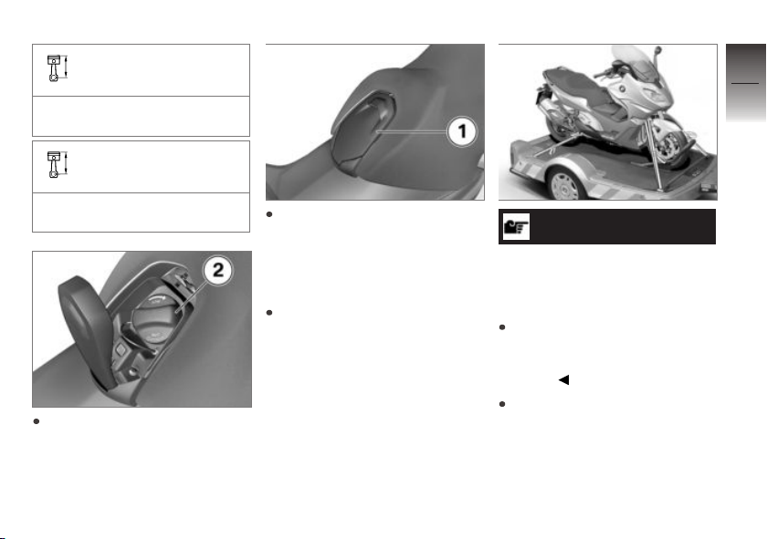
Usable fuel quantity
Approx. 4.1 gal (Approx.
15.5 l)
Fuel reserve
6
73
Approx. 3.2 quarts (Approx.
3 l)
Close the fuel filler cap 2.
Press tank cover 1 into locking
device.
Secure motorcycle for transport
Protect all components, along
which straps are routed,
against scratching. For
example, use adhesive tape or
soft cloths.
ATTENTION
Motorcycle tips to the side
when raising
Component damage cause by
tipping over
Secure the motorcycle against
tipping to the side, preferably
with the assistance of a second
person.
Push motorcycle onto transport
surface, and do not place on
side stand or center stand.
z
Riding
Page 76
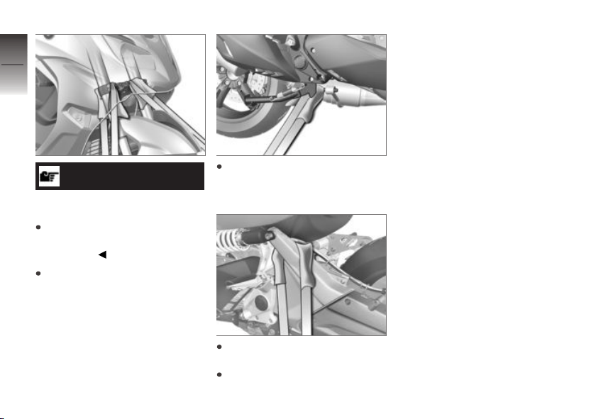
6
74
down against its springs with
the suspension compressed as
much as possible.
z
Riding
ATTENTION
Pinching of components
Component damage
Do not pinch components,
e.g. brake lines or wiring
harnesses.
Lay straps at front over lower
fork bridge on both sides and
tension.
Lay strap at rear right around
retaining pin of muffler and tension.
Lay strap at rear left around
spring strut mount and tension.
Tension all straps evenly; the
motorcycle should be pulled
Page 77

Technology in detail
General instructions . . . . . . . . . . . . . . . . . 76
Antilock Brake System (ABS) . . . . . . . 76
Automatic Stability Control
(ASC) . . . . . . . . . . . . . . . . . . . . . . . . . . . . . . . 78
Tire pressure control (TPC/RDC) . . . 79
7
75
z
Technology in detail
Page 78

General instructions
7
More information on the topic of
technology is available at:
76
bmw-motorrad.com/technol-
ogy
Antilock Brake System
(ABS)
How does the ABS work?
The maximum braking force that
can be transferred to the road
surface is partially dependent on
the friction coefficient of the road
surface. Gravel, ice, snow and
wet roads offer a considerably
poorer friction coefficient than a
z
Technology in detail
dry, clean asphalt surface. The
poorer the friction coefficient of
the road surface is, the longer
the braking distance will be.
If the maximum transferable
brake force is exceeded when
the driver increases the brake
pressure, the wheels begin to
lock and driving stability is lost.
A fall can occur. Before this
situation occurs, ABS intervenes
and adjusts the brake pressure
to the maximum transferable
braking force. This enables
the wheels to continue to turn
and maintains driving stability
regardless of the road surface
condition.
What happens when
rough roads are
encountered?
Bumpy or rough roads can briefly
lead to a loss of contact between
the tires and the road surface,
until the transferable braking
force is reduced to zero. If braking is carried out in this situation, the ABS reduces the brake
pressure to ensure driving stability when restoring contact to
the road. At this point in time,
the BMW Motorrad ABS must
assume extremely low friction
coefficients (gravel, ice, snow)
so that the road wheels turn in
every imaginable case and the
driving stability is ensured. After
detecting the actual conditions,
the system adjusts the optimum
brake pressure.
Lifting off rear wheel
Even during severe braking, a
high level of tire grip can mean
that the front wheel does not
lock up until very late, if at all.
Consequently, ABS does not
intervene until very late, if at
all. Under these circumstances
the rear wheel can lift off the
ground, and the outcome can be
a high-siding situation in which
the Maxi-Scooter can flip over.
Page 79

WARNING
Lifting off of the rear wheel
due to heavy braking
Accident hazard
When braking heavily, bear in
mind that the ABS control can-
not always be relied on to pre-
vent the rear wheel from lifting
off the ground.
What are the design
characteristics of the
BMW Motorrad ABS?
The BMW Motorrad ABS ensures driving stability on any
surface within the limits of driving physics. The system is not
optimized for the special conditions encountered under extreme
weather during off-road and racetrack use.
Special situations
To detect the tendency of the
wheels to lock up, the speeds
of the front and rear wheel are
compared. If implausible values
are detected over a longer period
of time, the ABS function is deactivated for safety reasons and
an ABS error is indicated. A selfdiagnosis routine must be completed before the error will be
displayed.
Apart from problems on the
BMW Motorrad ABS, unusual
riding conditions can also cause
a fault message to be generated.
Unusual driving conditions
When ASC is switched off:
Driving on the rear wheel
(wheelie) for an extended
period
Rear wheel rotating with the
vehicle held stationary by applying the front brake (burnout).
Rear wheel skidding on a slippery surface for a lengthy period, for example deceleration
using the engine's braking effect.
Should a fault code occur due to
an unusual driving condition, the
ABS function can be reactivated
by switching the ignition off and
then on again.
How important is regular
maintenance?
WARNING
Brake system not regularly
serviced
Accident hazard
To ensure that the
BMW Motorrad ABS is in a
properly maintained condition,
it is vital that the specified
service intervals are kept to.
7
77
z
Technology in detail
Page 80

Reserves for safety
7
But remember: the potentially
shorter braking distances which
78
BMW Motorrad ABS permits
must not be used as an excuse
for careless riding. ABS is pri-
marily a means of ensuring a
safety margin in genuine emer-
gencies.
Be careful in curves! When you
apply the brakes on a corner,
the motorcycle's weight and
momentum take over and even
BMW Motorrad ABS is unable to
counteract their effects.
Automatic Stability
z
Technology in detail
Control (ASC)
How does ASC work?
BMW Motorrad ASC compares
the wheel speeds of the front
and rear wheels. Differences in
the relative rotation speeds al-
low the system to determine the
slip rate, and thus the stability re-
serves at the rear wheel. The engine management system adapts
the engine torque when the slip
limit is exceeded.
Special situations
As lean angles increase, acceleration potential is also progressively restricted by the laws of
physics. This can result in delayed acceleration when coming
out of very tight curves.
The system compares the rotation speeds of the front and rear
wheels to detect any tendency
for the rear wheel to spin or lose
traction. If the system registers
implausible data for an extended
period of time it will deactivate
the ASC functionality as safety
precaution and a display will alert
you to an ASC error. A self-diagnosis routine must be completed
before the error will be displayed.
Driving on the rear wheel (performing Wheelies) for an ex-
tended period may cause the
ASC of the BMW Motorrad to
switch off automatically.
If the front wheel loses contact
to the ground during extreme
acceleration, the ASC reduces
the engine torque until the front
wheel touches the ground again.
BMW Motorrad recommends
that you respond to this condition by twisting back the throttle
grip somewhat to return to stable
dynamic operating conditions as
quickly as possible.
On smooth surfaces never completely twist the throttle grip back
in an abrupt manner. The engine's braking torque could cause
the rear wheel to lock, resulting
in unstable motorcycle conditions. This case cannot be controlled by BMW Motorrad ASC.
Page 81

Slippery roads
On very loose surfaces (e.g. sand
or snow) the control interventions of the ASC can reduce the
driving power at the rear wheel
to such a degree that the rear
wheel no longer turns sufficiently.
In this case, BMW Motorrad recommends switching off the ASC
temporarily.
Bear in mind that the rear wheel
will spin on the loose surface and
close the throttle in good time
before you reach a firm surface.
Then switch on the ASC again.
Tire pressure control (TPC/RDC)
with Tire Pressure Control
(TPC/RDC)
OE
Operation
A sensor located in each tire
monitors the pressure and air
temperature of the tire and transmits this information to the control unit.
The sensors are equipped with
a centrifugal controller that suppresses transmission of the measured values until a speed of approximately 18 mph (30 km/h)
is reached. Before initial reception of the tire pressure, "--"
is shown in the multifunction
display for each tire. The sensors continue to transmit the
monitored data for approximately
15 minutes after the motorcycle
comes to a stop.
Temperature
compensation
The tire inflation pressure is temperature dependent, i.e. it increases or decreases together
with the tire air temperature. The
tire air temperature is dependent
on the ambient temperature, the
driving style and the length of the
journey.
The tire pressures that appear
in the multifunction display are
temperature-compensated; they
are adjusted for a tire air temperature of 68 °F (20 °C). No
temperature compensation is
available in the pressure gages
at filling stations, meaning that
the measured tire pressure varies
according to tire air temperature.
As a result, the pressure figures
indicated by the gauges at filling stations will usually vary from
those appearing in the multifunction display.
7
79
z
Technology in detail
Page 82

Adjusting inflation
7
pressure
Compare the TCP/RDC value in
80
the multifunction display with the
value on the back cover of the
Rider's Manual. The difference
between the two values must
be compensated with the tire
inflation pressure tester at the
filling station.
Example: according to the
Rider's Manual, the tire inflation
pressure is to be 36 psi (2.5 bar),
however 33 psi (2.3 bar) is
shown in the multifunction
display. It is low by 3 psi
z
Technology in detail
(0.2 bar).
The tester at the filling station
indicates 34.8 psi (2.4 bar). This
value must be increased by 3 psi
(0.2 bar) to 37.8 psi (2.6 bar) in
order to produce the correct tire
inflation pressure.
Page 83

Maintenance
General instructions . . . . . . . . . . . . . . . . . 82
Standard tool kit . . . . . . . . . . . . . . . . . . . . 82
Front wheel stand . . . . . . . . . . . . . . . . . . 82
Engine oil . . . . . . . . . . . . . . . . . . . . . . . . . . . 84
Brake system . . . . . . . . . . . . . . . . . . . . . . . 86
Coolant . . . . . . . . . . . . . . . . . . . . . . . . . . . . . 91
Tyres . . . . . . . . . . . . . . . . . . . . . . . . . . . . . . . 93
Wheel rims and tyres . . . . . . . . . . . . . . . 93
Wheels . . . . . . . . . . . . . . . . . . . . . . . . . . . . . 94
Fuses . . . . . . . . . . . . . . . . . . . . . . . . . . . . . . . 99
Light sources . . . . . . . . . . . . . . . . . . . . . . 101
Jump-starting. . . . . . . . . . . . . . . . . . . . . . 107
Battery . . . . . . . . . . . . . . . . . . . . . . . . . . . . . 108
Fairings and panels . . . . . . . . . . . . . . . . 110
Diagnostic connector . . . . . . . . . . . . . . 113
8
81
z
Maintenance
Page 84
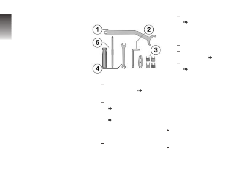
General instructions
8
The "Maintenance" chapter de-
scribes work involving the check-
82
ing and replacement of wear
parts that can be performed with
a minimum of effort.
If special tightening torques are
to be taken into account for
assembly, these are listed. An
overview of all required tightening
torques is contained in the
chapter "Technical Data".
Information on additional
z
Maintenance
maintenance and repair work is
provided in the repair instructions
for your vehicle on DVD, which
you can obtain from your
BMW Motorrad partner.
Special tools and thorough spe-
cialized knowledge are required
to carry out some of the work
described here. If you are in
doubt, consult an authorized
workshop, preferably your au-
thorized BMW Motorrad retailer.
Standard tool kit
1 Hook wrench
Adjusting spring preload
at rear wheel ( 61).
2 Torx wrench T30
Checking engine oil level
( 84).
Topping up coolant
( 92).
3 Spare fuses with gripper
Miniature fuses: 4 A,
7.5 A, 10 A and 15 A
Replace the fuses.
4 Open-ended wrench
Wrench size: 8/10 mm
4 Removing battery
( 109).
5 Reversible screwdriver in-
sert
Phillips PH1 and Torx T25
Remove body panels.
Replacing rear turn indicator bulb ( 105).
Removing battery
( 109).
Front wheel stand
Mount front wheel stand
Requirement
The base stand and its accessories are available through your
authorized BMW Motorrad retailer.
Make sure ground is level and
firm and place Maxi-Scooter on
its center stand.
Use basic stand with front
wheel mount.
Page 85
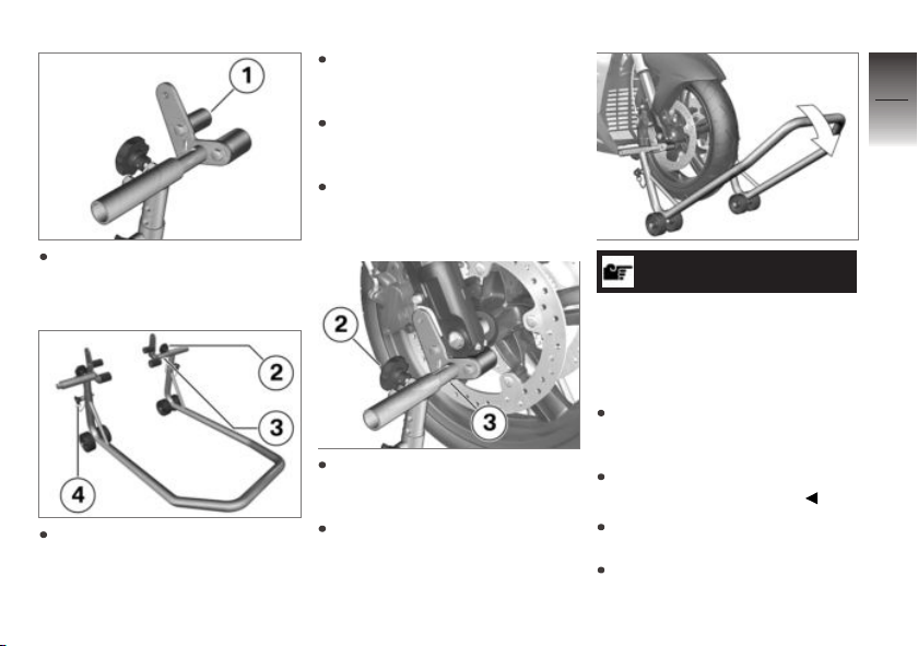
Install the spacer buffer 1 on
the left and right in the lower
position.
Loosen the mounting bolt 2 on
the left and right.
Push mounts 3 on left and
right far enough apart that front
suspension fits between them.
Use locating pins 4 on left and
right to set front wheel stand to
desired height.
Center front wheel stand relative to front wheel and push it
against front axle.
Align two mounts 3 on left and
right so that front suspension
rests securely on them.
Tighten the mounting bolt 2
firmly on the left and right.
ATTENTION
Lifting-off of the center stand
if the vehicle is raised too
high
Component damage cause by
tipping over
When raising the motorcycle, make sure that the center
stand remains on the ground.
Adjust the height of the front
wheel stand if necessary.
Press down front wheel stand
evenly to raise Maxi-Scooter.
Ensure Maxi-Scooter is standing securely.
8
83
z
Maintenance
Page 86
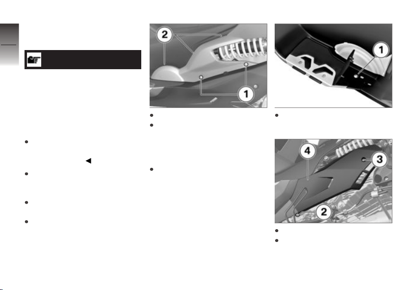
Engine oil
8
Checking engine oil level
84
z
Maintenance
ATTENTION
Incorrect oil level display after long immobilization period caused by oil collecting
in the oil sump instead of the
oil reservoir
Misinterpretation of the oil capacity
Only check the oil level after
a longer journey or when the
engine is warm.
Make sure ground is level and
firm and place Maxi-Scooter on
its center stand.
Allow engine to run in neutral
for one minute.
Switch off ignition.
Remove screws 1.
Pull cover outward at lower
side and remove. Mind the retaining lugs in position 2 while
doing so.
Extend side stand.
Lift step plate support and remove screw 1.
Remove screw 2 and screw 3.
Remove the footboard 4.
Page 87
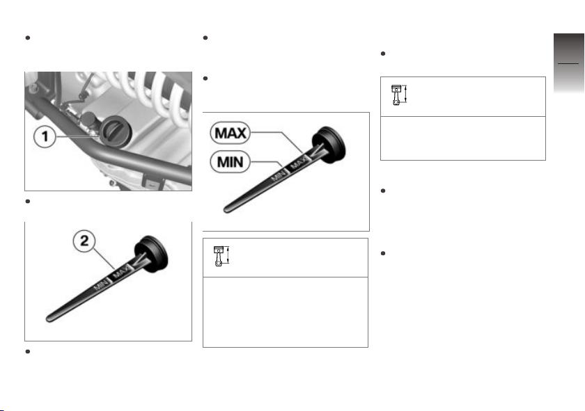
Wipe area around oil fill location to clean it.
Remove oil dipstick 1.
Clean the measuring range 2
on the oil dipstick with a dry
cloth.
Position the oil dipstick on the
oil filler opening, but do not
screw in.
Remove oil dipstick and read
fluid level.
Specified level of engine
oil
between MIN and MAX
marking (Engine at operating
temperature, merely put the
oil dipstick in place, do not
screw it in.)
If oil level is below MIN mark:
Add engine oil up to specified
level.
Engine oil, quantity for
topping up
max 0.5 quarts (max 0.5 l) (Difference between MIN and
MAX)
If oil level is above MAX mark:
Have oil level corrected at
an authorized service facility,
preferably an authorized
BMW Motorrad retailer.
Install oil dipstick.
8
85
z
Maintenance
Page 88
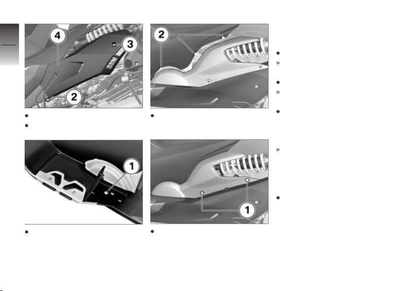
8
86
Position the footboard 4.
Install screw 2 and screw 3.
z
Maintenance
Install step plate support and
screw 1.
Mount cover at positions 2 and
engage.
Install screws 1.
Brake system
Check brake operation
Actuate right-hand brake lever.
Pressure point must be clearly
perceptible.
Actuate left-hand brake lever.
Pressure point must be clearly
perceptible.
To check the parking brake,
extend the side stand and try
to slide the Maxi-Scooter back
and forth.
It must not be possible to slide
the Maxi-Scooter.
If no clear resistance points can
be felt or if the Maxi-Scooter can
be pushed:
Have the brakes checked at an
authorized workshop, preferably
an authorized BMW Motorrad
retailer.
Page 89
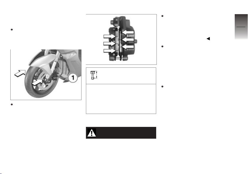
Check front brake pad
thickness
Make sure ground is level and
firm and place Maxi-Scooter on
its center stand.
Conduct a visual inspection
of the brake pad thickness.
Viewing direction: left and
right between wheel and front
suspension toward brake
pads 1.
Front brake-pad wear
limit
min 0.04 in (min 1.0 mm)
(Only friction material without
carrier plate. Wear markings
(grooves) must be clearly visible.)
If the wear indicators are no
longer clearly visible:
WARNING
Dropping below the minimum
pad thickness
Reduced braking action, damage
to the brake
In order to ensure the operating reliability of the brake system, make sure that the brake
pads are not worn beyond their
minimum thickness.
Have brake pads replaced at
an authorized service facility, preferably an authorized
BMW Motorrad retailer.
Checking rear brake pad
thickness
Make sure ground is level and
firm and place Maxi-Scooter on
its center stand.
8
87
z
Maintenance
Page 90
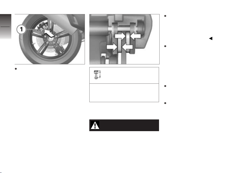
8
88
Conduct a visual inspection of
the brake pad thickness. Viewing direction: from lower right
toward brake pads 1.
z
Maintenance
Rear brake-pad wear
limit
min 0.04 in (min 1.0 mm)
(Only friction material without
carrier plate.)
If the wear indicating marks are
no longer visible:
WARNING
Dropping below the minimum
pad thickness
Reduced braking action, damage
to the brake
In order to ensure the operat-
ing reliability of the brake sys-
tem, make sure that the brake
pads are not worn beyond their
minimum thickness.
Have brake pads replaced at
an authorized service facil-
ity, preferably an authorized
BMW Motorrad retailer.
Checking brake pad
thickness of parking brake
Make sure ground is level and
firm and place Maxi-Scooter on
its center stand.
Conduct a visual inspection of
the brake pad thickness.
Page 91
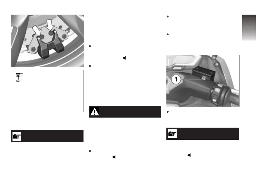
Brake-pad wear limit of
parking brake
The brake disc must not be
visible through the bore holes
on the carrier plate (clean bore
holes).
If brake pads have dropped below the minimum lining thickness:
ATTENTION
The parked vehicle rolls
away as a result of reduced
braking power caused by the
minimum lining thickness not
being met
Component damage caused by
tipping over, despite the side
stand being extended
Do not let the lining thickness
for the parking brake fall below
the minimum.
Have brake pads replaced at
an authorized service facility, preferably an authorized
BMW Motorrad retailer.
Checking brake fluid level
of front brake
WARNING
Insufficient brake fluid in the
brake-fluid reservoir
Considerably reduced braking
performance caused by air in the
brake system
Check brake fluid level
regularly.
Make sure ground is level and
firm and place Maxi-Scooter on
its center stand.
Align handlebars so that brakefluid reservoir is positioned horizontally.
Read off brake fluid level at
sight glass 1 of right-hand
brake-fluid reservoir.
NOTICE
The brake fluid level in the brakefluid reservoir drops due to brake
pad wear.
8
89
z
Maintenance
Page 92
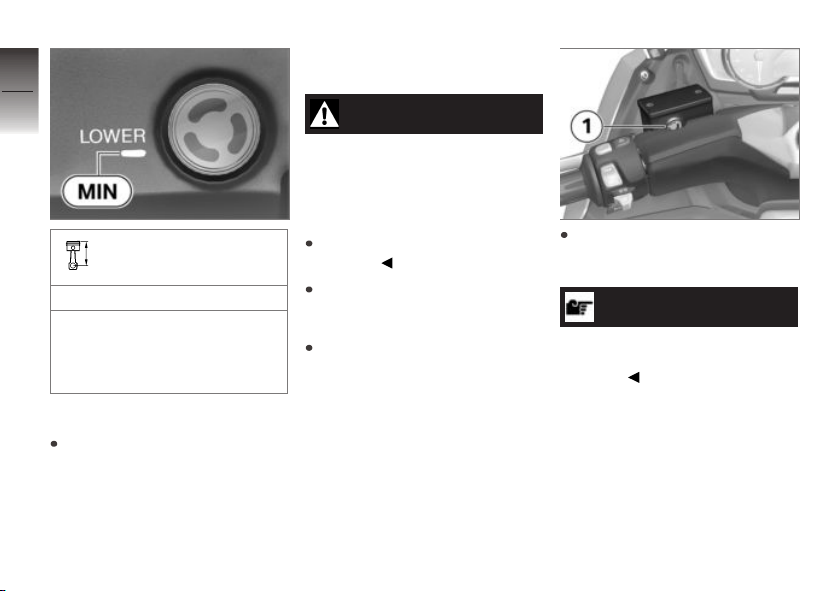
8
90
Front brake fluid level
Brake fluid, DOT4
z
Maintenance
The brake fluid level must
not fall below the MIN mark.
(Brake-fluid reservoir horizontal)
If brake fluid level falls below the
approved level:
Have defect corrected as soon
as possible by an authorized
workshop, preferably an authorized BMW Motorrad retailer.
Checking brake fluid level
for rear brake
WARNING
Insufficient brake fluid in the
brake-fluid reservoir
Considerably reduced braking
performance caused by air in the
brake system
Check brake fluid level
regularly.
Make sure ground is level and
firm and place Maxi-Scooter on
its center stand.
Align handlebars so that brakefluid reservoir is positioned horizontally.
Read off brake fluid level at
sight glass 1 of left-hand
brake-fluid reservoir.
NOTICE
The brake fluid level in the brakefluid reservoir drops due to brake
pad wear.
Page 93
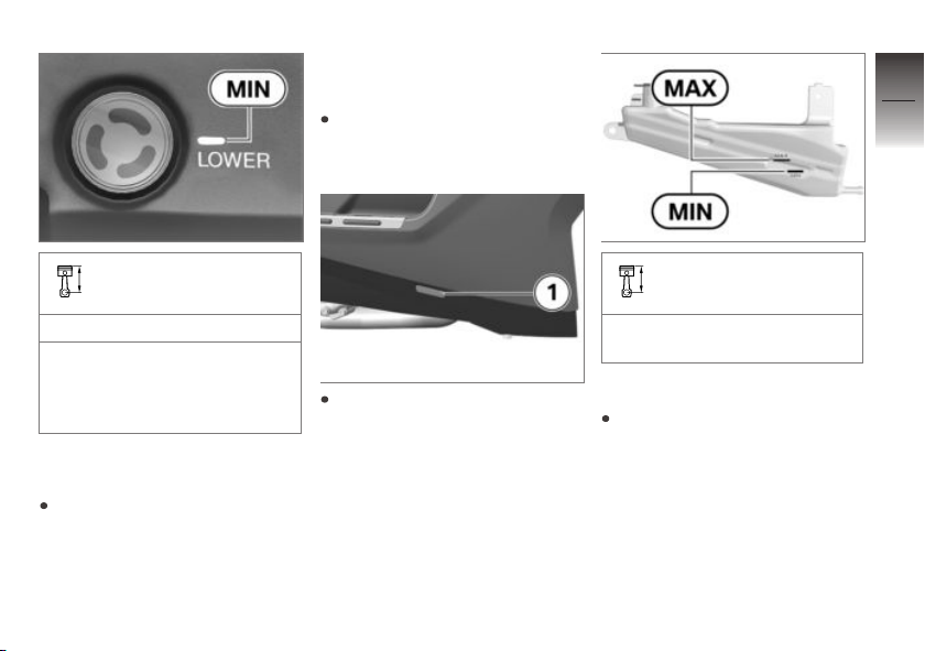
Coolant
Checking coolant level
Make sure ground is level and
firm and place Maxi-Scooter on
its center stand.
8
91
Rear brake fluid level
Brake fluid, DOT4
The brake fluid level must
not fall below the MIN mark.
(Brake-fluid reservoir horizontal)
If brake fluid level falls below the
approved level:
Have defect corrected as soon
as possible by an authorized
workshop, preferably an authorized BMW Motorrad retailer.
Read off the coolant level for
the expansion tank through the
opening 1 underneath the right
footboard.
Setpoint setting for
coolant in expansion tank
between MIN and MAX marking (With cold engine)
If coolant level drops below approved level:
Add coolant.
z
Maintenance
Page 94
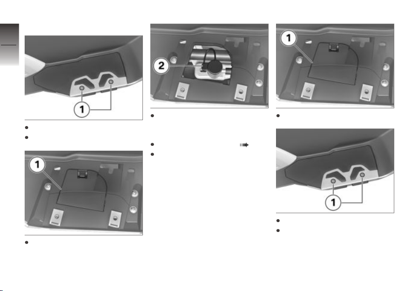
Topping up coolant
8
92
Remove screws 1.
Take off step plate support.
z
Maintenance
Open cover 1 and remove.
Open the cap 2 of the coolant
expansion tank and top up with
coolant to the specified level.
Checking coolant level ( 91).
Close the cap of the coolant
expansion tank.
Close cover 1.
Mount step plate support.
Install screws 1.
Page 95
Tyres
Checking tyre pressure
WARNING
Incorrect tire inflation pressure.
Scooter driving characteristics
impaired. ASC control characteristics impaired and tire service life
reduced.
Ensure proper tyre inflation
pressure.
WARNING
Automatic opening of vertically installed valve cores at
high speeds.
Sudden loss of tyre inflation
pressure.
Use valve caps with rubber
sealing ring and screw on
firmly.
Make sure ground is level and
firm and place Maxi-Scooter on
its center stand.
Check tyre pressures against
data below.
Tire pressure, front
36.3 psi (2.5 bar) (with tire
cold)
Tire pressure, rear
42.1 psi (2.9 bar) (with tire
cold)
If tyre pressure is too low:
Correct tyre pressure.
Wheel rims and tyres
Check wheel rims
Make sure ground is level and
firm and place Maxi-Scooter on
its center stand.
Subject wheel rims to visual
inspection for defects.
Have damaged rims checked
and, if necessary, replaced
by a specialist service facility, preferably an authorized
BMW Motorrad retailer.
Check tire tread depth
WARNING
Riding with heavily worn
tyres
Risk of accident due to poorer
rideability
If necessary, replace the tyres
before the legally specified
minimum tread depth is
reached.
Make sure ground is level and
firm and place Maxi-Scooter on
its center stand.
8
93
z
Maintenance
Page 96

Measure tire tread depth in
main tread grooves with wear
8
indicators.
94
NOTICE
Tread wear marks are integrated
into the main grooves on every
tire. If the tire tread has worn
down to the level of the marks,
the tire is completely worn. The
locations of the marks are indicated on the edge of the tire, e.g.
by the letters TI, TWI or by an
z
Maintenance
arrow.
When the minimum tread depth
is reached:
Replace the worn tires.
Wheels
Tyre recommendation
For every size of tyre,
BMW Motorrad has tested and
approved certain makes as
roadworthy. BMW Motorrad
cannot evaluate the suitability of
other tyres, and can therefore
take no responsibility for their
driving safety.
BMW Motorrad recommends
only using the tyres tested and
approved by BMW Motorrad.
Detailed information can be
obtained from your authorized
BMW Motorrad retailer or online
at:
bmw-motorrad.com
Affect of wheel size on
ABS
The wheel sizes play a major role
in the ABS system. The diameter and width of the wheels
stored in the control unit have
particular significance as the basis for all necessary calculations.
A change in these sizes resulting
from conversion to wheels not
installed as standard equipment
can seriously affect the control
efficiency of the system.
The sensor rings required for
wheel speed detection must also
match the system installed and
must not be replaced.
If you want to equip your MaxiScooter with different wheels,
please speak to a specialized
workshop, and preferably a
BMW Motorrad retailer. In some
cases the data stored in the
control unit can be adapted to
the new wheel sizes.
Effect of wheel sizes on
the ASC
The wheel sizes play a major role
in the ASC suspension control
system. The radii of the wheels
in particular are stored in the
control unit as the basis for all
necessary calculations. A change
in these sizes resulting from conversion to wheels not installed
as standard equipment can seriously affect the control efficiency
of these systems.
Page 97
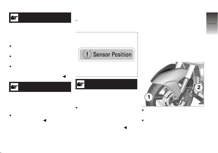
ATTENTION
Faults in the ASC caused by
changing tire radii
The ASC grips despite good adhesion
Check the wear and pressure
of both tires.
Calibrate the ASC after every
tire change.
If there are an unexpectedly
large number of ASC interventions: Recalibrate the ASC.
ATTENTION
Loss of the adaptation values
for the radii of the tires in the
Digital Motor Electronics
Accident hazard
Recalibrate the ASC after every
software update.
TPC/RDC sticker
with Tire Pressure Control
(TPC/RDC)
Improper tire removal
Damage to the TPC/RDC sensors
Inform a specialist service
facility or an authorized
BMW Motorrad retailer on the
fact that the wheel is equipped
with a TPC/RDC sensor.
On motorcycles equipped with
TPC/RDC, there is a sticker on
OE
ATTENTION
the wheel near to the position
of the TPC/RDC sensor. When
changing the tire, it is important
to take care not to damage the
TPC/RDC sensor. Draw the attention of the BMW Motorrad retailer or tire fitter to the TPC/RDC
sensor.
Removing front wheel
Remove the screws 1 and 2
on the left and right.
Take off the front wheel cover
toward the front.
8
95
z
Maintenance
Page 98
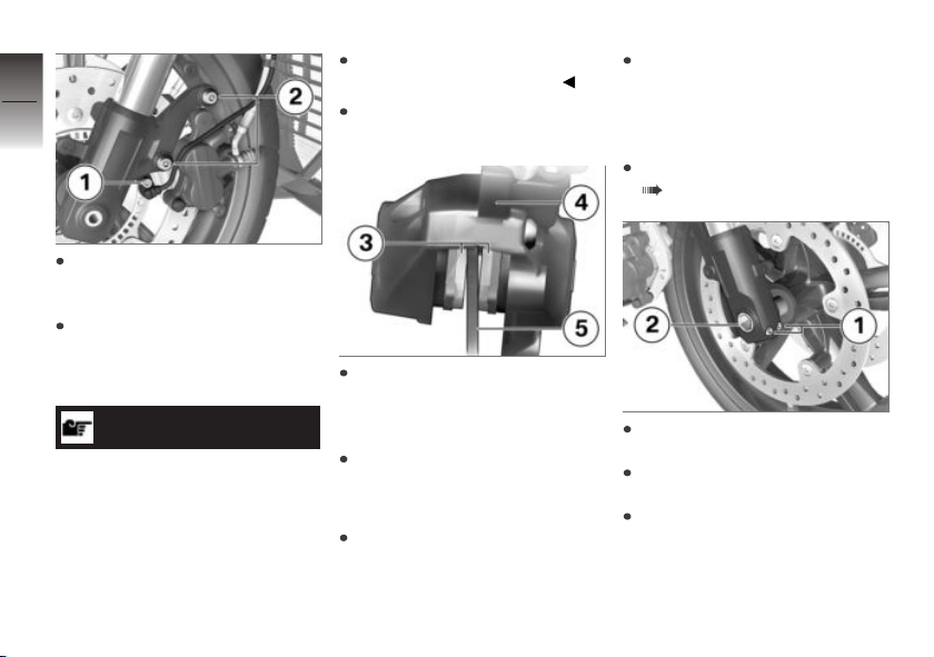
8
96
Remove the screw 1 and take
the ABS sensor out of the bore
hole.
Mask off areas of wheel rim
z
Maintenance
that could be scratched in the
process of removing the brake
calipers.
ATTENTION
Unintentional pressing together of brake pads
Component damage when
mounting the brake caliper or
when pressing the brake pads
apart
Do not actuate the brakes with
the brake caliper removed.
Remove screws 2 of brake
calipers on left and right.
Push brake pads 3 apart
slightly by turning brake
caliper 4 back and forth against
brake rotor 5.
Carefully pull brake calipers
back and outward to remove
them from brake rotors.
Make sure ground is level and
firm and place Maxi-Scooter on
its center stand.
Raise Maxi-Scooter at
front, preferably using a
BMW Motorrad front wheel
stand, until the front wheel
rotates freely.
Mount front wheel stand
( 82).
Loosen the clamping bolts 1
on the right.
Remove quick-release axle 2
while supporting wheel.
Roll front wheel forward to re-
move it.
Page 99
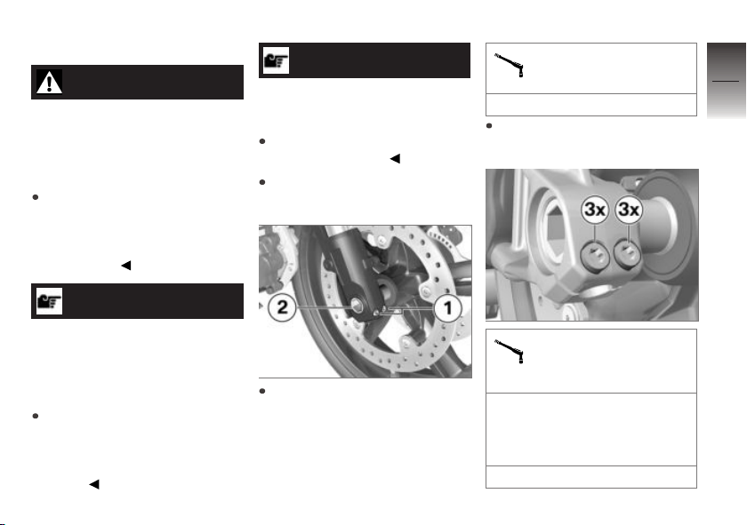
Installing front wheel
WARNING
Use of a wheel which does
not comply with series specifications
Malfunctions during control interventions by ABS and ASC
Please see the information on
the effect of wheel sizes on the
ABS and ASC chassis control
systems at the beginning of
this chapter.
ATTENTION
Tightening of screwed connections with incorrect tightening torque
Damage or loosening of screwed
connections
Always have the tightening
torques checked by a specialized workshop, preferably
an authorized BMW Motorrad
retailer.
ATTENTION
Front wheel installation opposite the running direction
Accident hazard
Observe running direction arrows on tire or rim.
Roll front wheel into front
suspension.
Lift front wheel and install
quick-release axle 2 with
torque.
Quick-release axle in axle
mount
22 lb/ft (30 Nm)
Tighten clamping screws 1 to
specified torque.
Clamping screws (quickrelease axle) in tele-
scopic forks
Tightening sequence: Tighten
the screws 6 times, alternating
between one and the other
each time
6 lb/ft (8 Nm)
8
97
z
Maintenance
Page 100
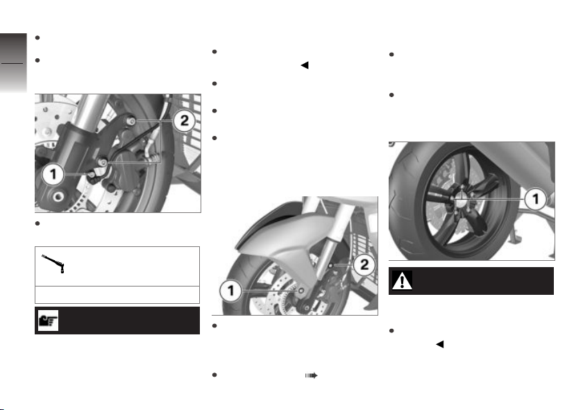
Remove front wheel stand.
8
Slide the brake calipers onto
98
the brake rotors.
z
Maintenance
Install screws 2 on left and
right with appropriate torque.
Brake caliper on fork leg
Sensor cable wearing through
Make sure that sensor cable is
routed correctly.
Insert ABS sensor into socket
and fit screw 1.
Remove adhesive tape from
wheel rim.
Apply strong pressure to the
handbrake lever, pulling repeatedly and continuing until the
point of resistance can be felt.
Removing rear wheel
Make sure ground is level and
firm and place Maxi-Scooter on
its center stand.
Extend the side stand to acti-
vate the parking brake, or apply
the rear wheel brake.
21 lb/ft (28 Nm)
ATTENTION
Contact between the wheel
speed sensor cable and the
brake disc
Mount front wheel cover and
install screws 1 and 2 on right
and left.
Calibrating ASC ( 51).
CAUTION
Hot exhaust system
Burn hazard
Do not touch hot exhaust
system.
 Loading...