


P8C WS
Motherboard

E7435
Revised Edition V2
May 2012
Copyright © 2012 ASUSTeK COMPUTER INC. All Rights Reserved.
No part of this manual, including the products and software described in it, may be reproduced, transmitted, transcribed, stored in a retrieval system, or translated into any language in any form or by any means, except documentation kept by the purchaser for backup purposes, without the express written permission of ASUSTeK COMPUTER INC. (“ASUS”).
Product warranty or service will not be extended if: (1) the product is repaired, modified or altered, unless such repair, modification of alteration is authorized in writing byASUS; or (2) the serial number of the product is defaced or missing.
ASUS PROVIDES THIS MANUAL “AS IS” WITHOUT WARRANTY OF ANY KIND, EITHER EXPRESS OR IMPLIED, INCLUDING BUT NOT LIMITED TO THE IMPLIED WARRANTIES OR CONDITIONS OF MERCHANTABILITY OR FITNESS FOR A PARTICULAR PURPOSE. IN NO EVENT SHALL ASUS, ITS DIRECTORS, OFFICERS, EMPLOYEES OR AGENTS BE LIABLE FOR ANY INDIRECT, SPECIAL, INCIDENTAL, OR CONSEQUENTIAL DAMAGES (INCLUDING DAMAGES FOR LOSS OF PROFITS, LOSS OF BUSINESS, LOSS OF USE OR DATA, INTERRUPTION OF BUSINESS AND THE LIKE), EVEN IF ASUS HAS BEEN ADVISED OF THE POSSIBILITY OF SUCH DAMAGES ARISING FROM ANY DEFECT OR ERROR IN THIS MANUAL OR PRODUCT.
SPECIFICATIONS AND INFORMATION CONTAINED IN THIS MANUAL ARE FURNISHED FOR INFORMATIONAL USE ONLY, AND ARE SUBJECT TO CHANGE AT ANY TIME WITHOUT NOTICE, AND SHOULD NOT BE CONSTRUED AS A COMMITMENT BY ASUS. ASUS ASSUMES NO RESPONSIBILITY OR LIABILITY FOR ANY ERRORS OR INACCURACIES THAT MAY APPEAR IN THIS MANUAL, INCLUDING THE PRODUCTS AND SOFTWARE DESCRIBED IN IT.
Products and corporate names appearing in this manual may or may not be registered trademarks or copyrights of their respective companies, and are used only for identification or explanation and to the owners’ benefit, without intent to infringe.
Offer to Provide Source Code of Certain Software
This product contains copyrighted software that is licensed under the General Public License (“GPL”), under the Lesser General Public License Version (“LGPL”) and/or other Free Open Source Software Licenses. Such software in this product is distributed without any warranty to the extent permitted by the applicable law. Copies of these licenses are included in this product.
Where the applicable license entitles you to the source code of such software and/or other additional data, you may obtain it for a period of three years after our last shipment of the product, either
(1)for free by downloading it from http://support.asus.com/download
or
(2)for the cost of reproduction and shipment, which is dependent on the preferred carrier and the location where you want to have it shipped to, by sending a request to:
ASUSTeK Computer Inc.
Legal Compliance Dept.
15 Li Te Rd.,
Beitou, Taipei 112
Taiwan
In your request please provide the name, model number and version, as stated in the About Box of the product for which you wish to obtain the corresponding source code and your contact details so that we can coordinate the terms and cost of shipment with you.
The source code will be distributed WITHOUT ANY WARRANTY and licensed under the same license as the corresponding binary/object code.
This offer is valid to anyone in receipt of this information.
ASUSTeK is eager to duly provide complete source code as required under various Free Open Source Software licenses. If however you encounter any problems in obtaining the full corresponding source code we would be much obliged if you give us a notification to the email address gpl@asus.com, stating the product and describing the problem (please DO NOT send large attachments such as source code archives, etc. to this email address).
ii

Contents
Notices ........................................................................................................................ |
vi |
Safety information..................................................................................................... |
vii |
About this guide........................................................................................................ |
viii |
P8C WS specifications summary............................................................................... |
x |
Chapter 1: |
Product introduction |
|
|
1.1 |
Welcome! |
..................................................................................................... |
1-1 |
1.2 |
Package contents....................................................................................... |
1-1 |
|
1.3 |
Special features.......................................................................................... |
1-2 |
|
|
1.3.1 ........................................................................ |
Product highlights |
1-2 |
|
1.3.2 ........................................ |
ASUS Workstation Exclusive Features |
1-3 |
|
1.3.3 ............................................................................. |
ASUS features |
1-4 |
Chapter 2: |
Hardware information |
|
|
2.1 |
Before you proceed.................................................................................... |
2-1 |
|
2.2 |
Motherboard overview............................................................................... |
2-2 |
|
|
2.2.1 |
Motherboard layout...................................................................... |
2-2 |
|
2.2.2 |
Central Processing Unit (CPU).................................................... |
2-4 |
|
2.2.3 |
System memory........................................................................... |
2-5 |
|
2.2.4 |
Expansion slots............................................................................ |
2-7 |
|
2.2.5 |
Onboard buttons and switches.................................................... |
2-9 |
|
2.2.6 |
Onboard LEDs........................................................................... |
2-12 |
|
2.2.7 |
Jumper....................................................................................... |
2-15 |
|
2.2.8 |
Internal connectors.................................................................... |
2-17 |
2.3 |
Building your computer system.............................................................. |
2-28 |
|
|
2.3.1 |
Additional tools and components to build a PC system............. |
2-28 |
|
2.3.2 |
CPU installation......................................................................... |
2-29 |
|
2.3.3 |
CPU heatsink and fan assembly installation.............................. |
2-31 |
|
2.3.4 |
DIMM installation....................................................................... |
2-33 |
|
2.3.5 |
Motherboard installation............................................................ |
2-34 |
|
2.3.6 |
ATX Power connection.............................................................. |
2-36 |
|
2.3.7 |
SATA device connection............................................................ |
2-37 |
|
2.3.8 |
Front I/O Connector................................................................... |
2-38 |
|
2.3.9 |
Expansion Card installation....................................................... |
2-39 |
|
2.3.10 |
Rear panel connection............................................................... |
2-40 |
|
2.3.11 |
Audio I/O connections................................................................ |
2-41 |
2.4 |
Starting up for the first time.................................................................... |
2-44 |
|
2.5 |
Turning off the computer......................................................................... |
2-44 |
|
iii

Contents
Chapter 3: |
BIOS setup |
|
|
3.1 |
Knowing BIOS............................................................................................. |
3-1 |
|
3.2 |
BIOS setup program................................................................................... |
3-1 |
|
|
3.2.1 |
EZ Mode...................................................................................... |
3-2 |
|
3.2.2 |
Advanced Mode........................................................................... |
3-3 |
3.3 |
Main menu................................................................................................... |
3-5 |
|
|
3.3.1 |
System Language ....................................................................... |
3-5 |
|
3.3.2 |
System Date ............................................................................... |
3-5 |
|
3.3.3 |
System Time ............................................................................... |
3-5 |
3.4 |
Ai Tweaker menu........................................................................................ |
3-8 |
|
3.5 |
Advanced menu........................................................................................ |
3-14 |
|
|
3.5.1 |
Trusted Computing.................................................................... |
3-14 |
|
3.5.2 |
CPU Configuration..................................................................... |
3-15 |
|
3.5.3 |
PCH Configuration..................................................................... |
3-17 |
|
3.5.4 |
SATAConfiguration.................................................................... |
3-18 |
|
3.5.5 |
SystemAgent Configuration...................................................... |
3-20 |
|
3.5.6 |
USB Configuration..................................................................... |
3-21 |
|
3.5.7 |
Onboard Devices Configuration................................................. |
3-22 |
|
3.5.8 |
APM........................................................................................... |
3-24 |
|
3.5.9 |
Network Stack............................................................................ |
3-25 |
3.6 |
Monitor menu............................................................................................ |
3-26 |
|
3.7 |
Boot menu................................................................................................. |
3-29 |
|
3.8 |
Tools menu................................................................................................ |
3-31 |
|
|
3.8.1 |
ASUS EZ Flash 2 Utility............................................................. |
3-31 |
|
3.8.2 |
ASUS O.C. Profile..................................................................... |
3-31 |
|
3.8.3 |
ASUS SPD Information.............................................................. |
3-32 |
3.9 |
Exit menu................................................................................................... |
3-33 |
|
3.10 |
Updating BIOS.......................................................................................... |
3-34 |
|
|
3.10.1 |
ASUS Update utility................................................................... |
3-34 |
|
3.10.2 |
ASUS EZ Flash 2 utility............................................................. |
3-37 |
|
3.10.3 |
ASUS CrashFree BIOS 3 utility................................................. |
3-38 |
|
3.10.4 |
ASUS BIOS Updater.................................................................. |
3-39 |
Chapter 4: |
Software support |
|
|
4.1 |
Installing an operating system.................................................................. |
4-1 |
|
4.2 |
Support DVD information........................................................................... |
4-1 |
|
|
4.2.1 |
Running the support DVD............................................................ |
4-1 |
|
4.2.2 |
Obtaining the software manuals.................................................. |
4-2 |
4.3 |
Installing AI Suite II..................................................................................... |
4-3 |
|
iv

Contents
|
4.3.1 |
EPU............................................................................................. |
4-4 |
|
4.3.2 |
FAN Xpert.................................................................................... |
4-5 |
|
4.3.3 |
Probe II........................................................................................ |
4-6 |
|
4.3.4 |
Sensor Recorder.......................................................................... |
4-7 |
|
4.3.5 |
ASUS Update.............................................................................. |
4-8 |
|
4.3.6 |
MyLogo........................................................................................ |
4-9 |
4.4 |
Audio configurations................................................................................ |
4-11 |
|
4.5 |
RAID configurations................................................................................. |
4-12 |
|
|
4.5.1 |
RAID definitions......................................................................... |
4-12 |
|
4.5.2 |
Installing Serial ATA hard disks.................................................. |
4-13 |
|
4.5.3 |
Setting the RAID item in BIOS................................................... |
4-13 |
|
4.5.4 |
Intel® Rapid Storage Technology Option ROM utility................. |
4-13 |
4.6 |
Creating a RAID driver disk..................................................................... |
4-27 |
|
|
4.6.1 |
Creating a RAID driver disk without entering the OS................. |
4-27 |
|
4.6.2 |
Creating a RAID driver disk in Windows®.................................. |
4-27 |
|
4.6.3 |
Installing the RAID driver during Windows® OS installation....... |
4-28 |
|
4.6.4 |
Using a USB floppy disk drive................................................... |
4-29 |
Chapter 5: |
Multiple GPU technology support |
|
|
5.1 |
AMD® CrossFireX™ technology............................................................... |
5-1 |
|
|
5.1.1 |
Requirements.............................................................................. |
5-1 |
|
5.1.2 |
Before you begin.......................................................................... |
5-1 |
|
5.1.3 |
Installing two CrossFireX™ graphics cards................................ |
5-2 |
|
5.1.4 |
Installing the device drivers......................................................... |
5-3 |
|
5.1.5 |
Enabling the AMD® CrossFireX™ technology............................ |
5-3 |

Notices
Federal Communications Commission Statement
This device complies with Part 15 of the FCC Rules. Operation is subject to the following two conditions:
•This device may not cause harmful interference, and
•This device must accept any interference received including interference that may cause undesired operation.
This equipment has been tested and found to comply with the limits for a Class B digital device, pursuant to Part 15 of the FCC Rules. These limits are designed to provide reasonable protection against harmful interference in a residential installation. This equipment generates, uses and can radiate radio frequency energy and, if not installed and used in accordance with manufacturer’s instructions, may cause harmful interference to radio communications. However, there is no guarantee that interference will not occur in a particular installation. If this equipment does cause harmful interference to radio or
television reception, which can be determined by turning the equipment off and on, the user is encouraged to try to correct the interference by one or more of the following measures:
•Reorient or relocate the receiving antenna.
•Increase the separation between the equipment and receiver.
•Connect the equipment to an outlet on a circuit different from that to which the receiver is connected.
•Consult the dealer or an experienced radio/TV technician for help.
The use of shielded cables for connection of the monitor to the graphics card is required to assure compliance with FCC regulations. Changes or modifications to this unit not expressly approved by the party responsible for compliance could void the user’s authority to operate this equipment.
Canadian Department of Communications Statement
This digital apparatus does not exceed the Class B limits for radio noise emissions from digital apparatus set out in the Radio Interference Regulations of the Canadian Department of Communications.
This class B digital apparatus complies with Canadian ICES-003.
REACH
Complying with the REACH (Registration, Evaluation, Authorisation, and Restriction of Chemicals) regulatory framework, we published the chemical substances in our products at ASUS REACH website at http://csr.asus.com/english/REACH.htm.
DO NOT throw the motherboard in municipal waste. This product has been designed to enable proper reuse of parts and recycling. This symbol of the crossed out wheeled bin indicates that the product (electrical and electronic equipment) should not be placed in municipal waste. Check local regulations for disposal of electronic products.
DO NOT throw the mercury-containing button cell battery in municipal waste. This symbol of the crossed out wheeled bin indicates that the battery should not be placed in municipal waste.
vi

Safety information
Electrical safety
•To prevent electrical shock hazard, disconnect the power cable from the electrical outlet before relocating the system.
•When adding or removing devices to or from the system, ensure that the power cables for the devices are unplugged before the signal cables are connected. If possible, disconnect all power cables from the existing system before you add a device.
•Before connecting or removing signal cables from the motherboard, ensure that all power cables are unplugged.
•Seek professional assistance before using an adapter or extension cord. These devices could interrupt the grounding circuit.
•Ensure that your power supply is set to the correct voltage in your area. If you are not sure about the voltage of the electrical outlet you are using, contact your local power company.
•If the power supply is broken, do not try to fix it by yourself. Contact a qualified service technician or your retailer.
Operation safety
•Before installing the motherboard and adding devices on it, carefully read all the manuals that came with the package.
•Before using the product, ensure all cables are correctly connected and the power cables are not damaged. If you detect any damage, contact your dealer immediately.
•To avoid short circuits, keep paper clips, screws, and staples away from connectors, slots, sockets and circuitry.
•Avoid dust, humidity, and temperature extremes. Do not place the product in any area where it may become wet.
•Place the product on a stable surface.
•If you encounter technical problems with the product, contact a qualified service technician or your retailer.
vii

About this guide
Thisuserguidecontainstheinformationyouneedwheninstallingandconfiguringthemotherboard.
How this guide is organized
This guide contains the following parts:
•Chapter 1: Product introduction
This chapter describes the features of the motherboard and the new technology it supports.
•Chapter 2: Hardware information
This chapter lists the hardware setup procedures that you have to perform when installing system components. It includes description of the switches, jumpers, and connectors on the motherboard.
•Chapter 3: BIOS setup
This chapter tells how to change system settings through the BIOS Setup menus. Detailed descriptions of the BIOS parameters are also provided.
•Chapter 4: Software support
This chapter describes the contents of the support DVD that comes with the motherboard package and the software.
•Chapter 5: Multiple GPU technology support
This chapter describes how to install and configure multipleATI® CrossFireX™ and NVIDIA® SLI™ graphics cards.
Where to find more information
Refer to the following sources for additional information and for product and software updates.
1.ASUS websites
The ASUS website provides updated information on ASUS hardware and software products. Refer to the ASUS contact information.
2.Optional documentation
Your product package may include optional documentation, such as warranty flyers, that may have been added by your dealer. These documents are not part of the standard package.
viii

Conventions used in this guide
To ensure that you perform certain tasks properly, take note of the following symbols used throughout this manual.
DANGER/WARNING: Information to prevent injury to yourself when trying to complete a task.
CAUTION: Information to prevent damage to the components when trying to complete a task.
IMPORTANT: Instructions that you MUST follow to complete a task.
NOTE: Tips and additional information to help you complete a task.
Typography
Bold text |
Indicates a menu or an item to select. |
Italics |
Used to emphasize a word or a phrase. |
<Key> |
Keys enclosed in the less-than and greater-than sign means |
|
that you must press the enclosed key. |
|
Example: <Enter> means that you must press the Enter or |
|
Return key. |
<Key1> + <Key2> + <Key3> |
If you must press two or more keys simultaneously, the key |
|
names are linked with a plus sign (+). |
|
Example: <Ctrl> + <Alt> + <Del> |
ix
P8C WS specifications summary
CPU
Chipset
Memory
Expansion slots
VGA
Output
Multi-GPU support
Storage
LAN
USB
1394
Audio
Workstation Unique Features
BIOS features
Manageability
LGA1155 socket for Intel® 2nd / 3rd Generation Core™ i3 desktop processor LGA1155 socket for Intel® Xeon® E3-1200/ 12x5 v2 series processor Supports 32nm / 22nm CPU
*Supports Intel® Turbo Boost technology 2.0.
**Refer to www.asus.com for Intel® CPU support list.
Intel® C216 Chipset
4 x DIMMs, max. 32GB, DDR3 1600 / 1333 MHz, ECC non-ECC, un-buffered memory
Dual-channel architecture
Supports Intel® Extreme Memory Profile (XMP)
**Refer to www.asus.com or this user manual for the Memory QVL (Qualified
Vendors Lidts)
1 x PCIe 3.0 x16 (at x16 or x8) (blue) 1 x PCIe 3.0 x16 (at x8) (black)
2 x PCIe 2.0 x16 (at x4) (white)
1 x PCIe 2.0 x1 (at x1)
1 x PCI
DVI-I port
Supports DVI with max. resolution 1920 x 1200 at 60Hz
Maximum shared memory of 1GB
Supports ATI® Quad-GPU CrossFireX™ Technology
Intel® C216 Chipset:
-2 x SATA 6.0 Gb/s ports(gray)
-4 x SATA 3.0 Gb/s ports(blue)
-Intel® Rapid Storage Technology supports RAID 0, 1, 5, and 10
*Supports on Intel® Smart Response Technology, Intel® Rapid Start Technology, Intel® Smart ConnectTechnology *
**Supports on Intel® Core™ processor family with Windows 7 operating systems.
2*Intel® 82574L GbE LAN
- Support teaming function
Intel® C216 Chipset:
-4 x USB 3.0 ports (2 ports at mid-board, 2 ports at back panel)
-10 x USB 2.0 ports (4 ports at mid-board, 6 ports at back panel)
VIA VT6308S controller supports 2 x 1394a port
Realtek® ALC892 8-channel High DefinitionAudio CODEC
-BD audio layer content protection
-Supports Jack-Detection, Multi-streaming and Front Panel Jack-Retasking
-Optical S/PDIF out ports at back I/O
4 PCIe x 16 slots
G.P. Diagnosis Card bundled
Quick Gate: 1 vertical USB 2.0 on board
64 Mb Flash ROM, UEFI AMI BIOS, PnP, DMI2.0, WfM2.0, SM BIOS 2.6, ACPI 2.0a, Multi-language BIOS, ASUS EZ Flash Utility, ASUS CrashFree BIOS 3
WfM 2.0, DMI 2.0, WOL by PME, WOR by PME, PXE
(continued on the next page)
P8C WS specifications summary
ASUS
Unique
Features
Back Panel I/O
Ports
Internal I/O connectors
OS
Form factor
GPU Boost with switch
ASUS Power Design
-8+2 Phase Power Design
ASUS EPU
-EPU, EPU Switch
ASUS Exclusive Features
-MemOK!
-AI Suite II
-Anti Surge
-ASUS EFI BIOS EZ Mode featuring friendly graphics user interface
ASUS Quiet Thermal Solution:
-ASUS Fanless Design: Heat-pipe solution
-ASUS Fan Xpert
ASUS EZ DIY:
-ASUS Q-Connector
-ASUS CrashFree BIOS 3
-ASUS EZ Flash Utility
1 x PS/2 KB/MS port
1 x S/PDIF Out (Optical and Coxial)
6 x USB 2.0/ 1.1 ports
2 x USB 3.0/ 2.0 ports
1 x IEEE 1394a
2 x Lan Connector
1 x DVI-I port
6 x Audio jacks
1 x USB 3.0/2.0 connector supports additional 2 USB ports (19-pin) 1 x USB 2.0/1.1 connectors support additional 4 USB ports
2 x USB 2.0/1.1 vertical ports
24-pin ATX Power connector
8-pin ATX +12V Power connector CPU Fan with PWM control Chassis fan1 with Q-fan control Chassis fan2 with Q-fan control Chassis fan3 with Q-fan control Power fan
AAFP connector
1 x COM port connector
1 x TPM header
1 x 1394a connector
1 x LTP1 header S/PDIF Out header 1 x MemOK! Button
20-pin front panel connector
Win7 32/ 64 bit, WinXP 32/ 64 bit, Server 2003, Server 2008 and Server 2008 R2
ATX Form Factor, 12in x 9.6in (30.5cm x 24.5cm)
*Specifications are subject to change without notice.
xi

xii
Chapter 1
Chapter 1: |
Product introduction |
1.1Welcome!
Thank you for buying an ASUS® P8C WS motherboard!
The motherboard delivers a host of new features and latest technologies, making it another standout in the long line of ASUS quality motherboards!
Before you start installing the motherboard, and hardware devices on it, check the items in your package with the list below.
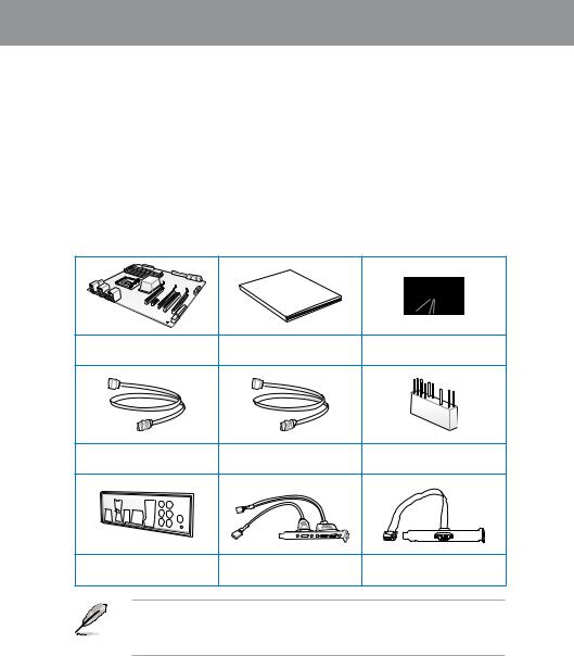
1.2Package contents
Check your motherboard package for the following items.
Manual
User
ASUS P8C WS motherboard |
User manual |
Support DVD |
2 x Serial ATA 6.0 Gb/s cables 4 x Serial ATA 3.0 Gb/s cables 1 x 2-in-1 ASUS Q-Connector kit
1 x ASUS Q-Shield |
2 USB ports + 1394a cable |
|
with bracket |
||
|
1 x COM port cable with bracket
•If any of the above items is damaged or missing, contact your retailer.
•The illustrated items above are for reference only.Actual product specifications may vary with different models.
ASUS P8C WS |
1-1 |

1 Chapter
1.3Special features
1.3.1Product highlights
Green ASUS
This motherboard complies with the European Union’s Energy-related Products (ErP) requirements, which requires products to meet certain energy efficiency criteria for energy consumption. This in in keeping with ASUS’ vision of creating environment-friendly and energy-efficient products to reduce a product’s carbon footprint and reduce its environmental impact.
LGA1155 socket for Intel® Second/Third Generation Core™ i3 and Xeon® E3-1200/ 12x5 v2 processors
This motherboard supports the latest Intel® 3rd/2nd generation Core™ i3 and Xeon® E3-1200/ 12x5 v2 processors in the LGA1155 package, with memory and PCI Express controllers to support 2-channel (4 DIMMs) DDR3 memory and 16 PCI Express 3.0 lanes for great graphics performance.
C216
Intel® C216 Express Chipset is a single-chipset that supports the 1155 socket Intel® 2nd / 3rd generation Core™ i3 and Intel® Xeon E3-1200 v2 server processors. It utilizes the serial point-to-point links, which increases bandwidth and enhances the system’s performance. It comes with two SATA 6Gb/s and four SATA 3Gb/s ports for faster data retrieval, doubling the bandwidth of the current bus systems. It also enables the iGPU function for the latest Intel® integrated graphics performance.
PCI Express® 3.0
PCI Express® 3.0 (PCIe 3.0) is the latest PCI Express bus standard that provides twice the performance and speed of PCIe 2.0. It provides an optimal graphics performance,
unprecedented data speed, and seamless transition with its complete backward compatibility to PCIe 1.0/2.0 devices.
Dual-Channel DDR3 1600/ 1333 support
This motherboard supports the dual-channel DDR3 architecture that features the data transfer rates of DDR3 1600/1333 MHz to boost the system’s performance, and to meet the higher bandwidth requirements of the latest 3D graphics, multimedia, and Internet applications.
Native SATA 6Gb/s Support
With its Intel® C216 Chipset, this motherboard natively supports the next generation Seria ATA (SATA) storage interface, delivering up to 6.0 Gb/s data transfer rates. It provides enhanced scalability, faster data retrieval, and twice the bandwidth of current bus systems.
1-2 |
Chapter 1: Product Introduction |

Complete USB 3.0 Integration
This motherboard offers you the strategic USB 3.0 accessibility for both the front and rear panels, allowing you to experience the convenience of the latest plug & play connectivity solution at speed up to ten times faster than USB 2.0.
GPU Boost
GPU Boost accelerates the integrated GPU for extreme graphics performance, facilitates flexible frequency adjustments, and easily delivers stable system-level upgrades for every use.
EPU
EPU (Energy Processing Unit), the world’s first real-time system power-saving chip, automatically detects the current system load and intelligently moderates power usage.
It offers a total system-wide energy optimization, reduces fan noise, and extends the components’ lifespan.
1.3.2ASUS Workstation Exclusive Features
Dual Intel® LAN
This motherboard features the built-in dual server class Intel® Gigabit LAN ports, which help reduce CPU usage, thus increasing throughput to achieve highly-reliable network connections, outstanding performance, and better support for diverse operating systems.
Multi CPU and Memory support
This motherboard offers you with flexible options on CPU and memory support to meet diverse computing needs.
For instance, you can choose to use the widely-available DDR3 un-buffered non-ECC memory modules or the more stable and reliable DDR3-unbuffered ECC memory modules.
CUDA parallel computing power support
This motherboard works with the discrete CUDA technology to attain the outstanding and dependable performance of a Personal Supercomputer on your desk instead of a computer cluster in a room, providing you with an unprecedented return on your investment. Its Tesla GPUs offers an intensive parallel computing on tons of data, which delivers up to four teraflops of performance.
Chapter 1
ASUS P8C WS |
1-3 |

1 Chapter
Quick Gate
Quick Gate is a vertical USB connector on the motherboard that allows you to install USB devices directly without any messy cables and stops important data storage devices from breaking off unexpectedly. This revolutionary and unique design offers a convenient and safe way to install data and applications on your system.
Diagnosis LED
Diag. LED offers an intuitive way to locate the root problems in seconds. It checks these key components in sequence during bootup --- CPU, memory, graphics card, and hard drive. If an error is found, the critical component’s LED stays lit up until the problem is solved.
G.P. Diagnosis Card (Bundled)
The bundled G.P. Diagnosis card double-checks the system quickly provides precise information everytime you turn on your computer.
1.3.3ASUS features
8+2 Phase Power Design
This motherboard’s 8-phase VRM power design unleashes the Intel® Ivy Bridge processor’s potential, delivering high-power efficiency, supreme overclocking ability, and effectively lowers the system’s temperature to extend the components’ lifespan. This motherboard also features an extra 2-phase power area for the integrated memory controller.
MemOK!
MemOK!, the remarkable memory rescue tool, allows you to simply press a button to patch memory issues, ensure memory boot compatibility, determine fail-safe settings, and dramatically improve the system’s bootup.
AI Suite II
With its user-friendly interface, ASUS AI Suite II integrates several ASUS utilities and allows you to launch and operate these utilities simultaneously. It allows you to configure the overclocking settings, adjust the frequencies and related voltages, remotely control the system via a mobile device, and other easy-to-use and helpful utilities.
ASUS Quiet Thermal Solution
ASUS Quiet Thermal solution provides a more stable system and enhances the overclocking capability.
1-4 |
Chapter 1: Product Introduction |

ASUS Fanless Design—Heat-pipe solution
The aesthetically-designed crystal-shaped heatsink features the 0-dB thermal solution for a noiseless and stable computing environment.
DO NOT uninstall the heat-pipe by yourself. Doing so may bend the tubing and affect the heat dissipation performance.
Fan Xpert
ASUS Fan Xpert intelligently allows you to adjust both the CPU and chassis fan speeds based on different ambient temperatures and attain a quiet and cool computing environment.
ASUS EZ DIY
ASUS UEFI BIOS(EZ Mode)
ASUS UEFI BIOS, a UEFI compliant architecture, offers the first mouse-controlled intuitive graphical BIOS interface that goes beyond the traditional keyboard-only BIOS controls, providing you with more flexibility, convenience, and easy to navigate EFI
BIOS than the traditional BIOS versions. It offers you with dual selectable modes and native support for hard drives larger than 2.2 TB.
ASUS UEFI BIOS includes the following new features:
*F12 BIOS snapshot hotkey
*F3 Shortcut for most accessed information
*ASUS DRAM SPD (Serial Presence Detect) information detecting faulty DIMMs, and helping with difficult POST situations
ASUS Q-Design
ASUS Q-Design enhances your DIY experience. All of Q-LED, Q-DIMM, and Q-Slot design speed up and simplify the DIY process!
ASUS Q-Connector
ASUS Q-Connector is a unique adapter that allows you to easily connect or disconnect the chassis front panel cables to one module, eliminating the hassle of plugging one cable at a time and making the connection quick and accurate.
ASUS EZ Flash 2
ASUS EZ Flash 2 is a user-friendly utility that allows you to update the BIOS without using a bootable floppy disk or an OS-based utility.
Chapter 1
ASUS P8C WS |
1-5 |

1 Chapter
ASUS CrashFree BIOS 3
ASUS CrashFree BIOS 3 allows you to restore a corrupted BIOS file from a USB storage device containing the BIOS file.
Precision Tweaker 2
Precision Tweaker 2 allows you to adjust the CPU voltager in 0.01V steps and the DRAM voltage in 0.001V steps to achieve the most precise and ultimate overclocking settings.
IEEE 1394a interface
IEEE 1394a interface provides high speed digital interface for audio/video devices such as digital television, digital video camcorders, storage peripherals and other portable devices.
S/PDIF-out on Back I/O Port
This motherboard provides the coaxial and optical S/PDIF out ports for convenient connectivity to external home theater audio systems and for high-quality digital audio experience.
ASUS Crystal Sound
8 Channel Audio Codec
The onboard 8-channel HD audio (High DefinitionAudio, previously codenamed Azalia) CODEC enables high-qualityAbsolute Pitch 192khz/24bit audio output, true
BD lossless sound, jack-sensing feature, retasking functions, and multi-streaming technology.
1-6 |
Chapter 1: Product Introduction |

Chapter 2
Chapter 2: |
Hardware information |
2.1Before you proceed
Take note of the following precautions before you install motherboard components or change any motherboard settings.
• Unplug the power cord from the wall socket before touching any component.
• Before handling components, use a grounded wrist strap or touch a safely grounded object or a metal object, such as the power supply case, to avoid damaging them due to static electricity.
•Hold components by the edges to avoid touching the ICs on them.
•Whenever you uninstall any component, place it on a grounded antistatic pad or in the bag that came with the component.
•Before you install or remove any component, ensure that the ATX power supply is switched off or the power cord is detached from the power supply. Failure to do so may cause severe damage to the motherboard, peripherals, or components.
ASUS P8C WS |
2-1 |

2.2Motherboard overview
2.2.1Motherboard layout
2 Chapter
Refer to 2.2.8 Internal connectors and 2.3.10 Rear panel connection for more information about rear panel connectors and internal connectors.
2-2 |
Chapter 2: Hardware information |
Layout contents
Connectors/Jumpers/Switches/Slots |
Page |
|
1. |
LGA1155 CPU Socket |
2-4 |
2. |
Power connectors (24-pin EATXPWR, 8-pin EATX12V) |
2-26 |
3. |
DDR3 DIMM slots |
2-5 |
4. |
CPU, chassis, and power fan connectors (4-pin CPU_FAN, |
2-22 |
|
4-pin CHA_FAN1-3, 3-pin PWR_FAN) |
|
5. |
MemOK! switch |
2-11 |
6. |
USB 3.0 connector (20-1 pin USB3_12) |
2-20 |
7. |
Intel® C216 Serial ATA 6.0 Gb/s connectors |
2-17 |
|
(7-pin SATA6G_1-2 [gray]) |
|
8. |
Intel® C216 Serial ATA 3.0 Gb/s connectors |
2-18 |
|
(7-pin SATA3G_3–6 [blue]) |
|
9. |
Standby Power LED |
2-13 |
10. |
System panel connector (20-8 pin PANEL) |
2-27 |
11. |
Clear RTC RAM (3-pin CLRTC) |
2-15 |
12. |
USB 2.0 connectors |
2-19 |
|
(TypeA: 10-1 pin USB1314; Type B: USB11/ USB12) |
|
13. |
Parallel port connector (26-1 pin LPT1) |
2-20 |
14. |
TPM connector (20-1 pin TPM) |
2-24 |
15. |
Serial port connector (10-1 pin COM1) |
2-23 |
16. |
Digital audio connector (4-1 pin SPDIF_OUT) |
2-21 |
17. |
IEEE 1394a port connector (10-1 pin IE1394_2) |
2-21 |
18. |
GPU Boost Switch |
2-10 |
19. |
EPU Switch |
2-9 |
20. |
Chassis Fan control setting (3-pin CHAFAN_SEL) |
2-16 |
21. |
Front panel audio connector (10-1 pin AAFP) |
2-23 |
Chapter 2
ASUS P8C WS |
2-3 |
2 Chapter
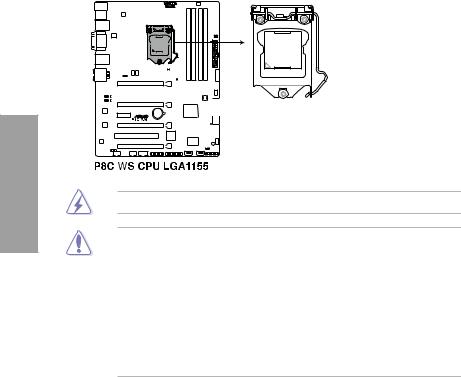
2.2.2Central Processing Unit (CPU)
The motherboard comes with a surface mount LGA1155 socket designed for the Intel® 2nd/ 3rd Generation Core™ i3 desktop Processors and Intel® Xeon® E3-1200/ 12x5 v2 series Server/Workstation Processors.
Ensure that all power cables are unplugged before installing the CPU.
•Upon purchase of the motherboard, ensure that the PnP cap is on the socket and the socket contacts are not bent. Contact your retailer immediately if the PnP cap is missing, or if you see any damage to the PnP cap/socket contacts/motherboard components. ASUS will shoulder the cost of repair only if the damage is shipment/ transit-related.
•Keep the cap after installing the motherboard. ASUS will process Return Merchandise
Authorization (RMA) requests only if the motherboard comes with the cap on the
LGA1155 socket.
•The product warranty does not cover damage to the socket contacts resulting from incorrect CPU installation/removal, or misplacement/loss/incorrect removal of the PnP cap.
2-4 |
Chapter 2: Hardware information |

2.2.3System memory
The motherboard comes with four Double Data Rate 3 (DDR3) Dual Inline Memory Modules (DIMM) slots.
A DDR3 module is notched differently from a DDR or DDR2 module. DO NOT install a DDR or DDR2 memory module to the DDR3 slot.
Chapter 2
Recommended memory configurations
ASUS P8C WS |
2-5 |

Memory configurations
You may install 1GB, 2GB, 4GB, 8GB unbuffered ECC or non ECC DDR3 DIMMs into the DIMM sockets depending on the installed CPU.
•You may install varying memory sizes in ChannelAand Channel B. The system maps the total size of the lower-sized channel for the dual-channel configuration.Any excess memory from the higher-sized channel is then mapped for single-channel operation.
2 Chapter
•According to Intel CPU spec, DIMM voltage below 1.65V is recommended to protect the CPU.
•The max. 32GB memory capacity can be supported with DIMMs of 8GB (or above).
•Always install DIMMs with the same CAS latency. For optimum compatibility, we recommend that you obtain memory modules from the same vendor.
•Due to the memory address limitation on 32-bit Windows OS, when you install 4GB or more memory on the motherboard, the actual usable memory for the OS can be about 3GB or less. For effective use of memory, we recommend that you do any of the following:
-Use a maximum of 3GB system memory if you are using a 32-bit Windows OS.
-Install a 64-bit Windows OS when you want to install 4GB or more on the motherboard.
For more details, refer to the Microsoft® support site at http://support.microsoft.com/kb/929605/en-us.
•This motherboard does not support DIMMs made up of 512Mb (64MB) chips or less (Memory chip capacity counts in Megabit, 8 Megabit/Mb = 1 Megabyte/MB).
For system stability, use a more efficient memory cooling system to support a full memory load (4 DIMMs) or overclocking condition.
P8C WS Motherboard Qualified Vendors Lists (QVL)
•ASUS exclusively provides hyper DIMM support function.
•Hyper DIMM support is subject to the physical characteristics of individual CPUs. Load the X.M.P. or D.O.C.P. settings in the BIOS for the hyper DIMM support.
•Visit the ASUS website for the latest QVL.
2-6 |
Chapter 2: Hardware information |
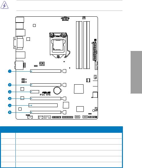
2.2.4Expansion slots
Ensure to unplug the power cord before adding or removing expansion cards. Failure to do so may cause you physical injury and damage motherboard components.
Chapter 2
Slot No. Slot Description
1PCIe 3.0 x16_1 slot (single at x16 or dual at x8/x8 mode)
2PCIe 3.0 x16_2 slot (x8 mode)
3PCIe 2.0 x1_1 slot
4PCIe 2.0 x16_3 slot (x4 mode)
5PCI1 slot
6PCIe 2.0 x16_4 slot (x4 mode)
ASUS P8C WS |
2-7 |
2 Chapter
Standard Interrupt assignments
IRQ |
Priority |
Standard function |
0 |
1 |
System Timer |
1 |
2 |
Keyboard Controller |
2 |
- |
Programmable Interrupt |
4 |
12 |
Communications Port (COM1) |
5 |
13 |
IRQ Holder for PCI Steering |
6 |
14 |
Reserved |
7 |
15 |
Reserved |
8 |
3 |
System CMOS/Real Time Clock |
9 |
4 |
IRQ Holder for PCI Steering |
10 |
5 |
IRQ Holder for PCI Steering |
11 |
6 |
IRQ Holder for PCI Steering |
12 |
7 |
Reserved |
13 |
8 |
Numeric Data Processor |
14 |
9 |
Primary IDE Channel |
IRQ assignments for this motherboard
|
A |
B |
C |
D |
E |
F |
G |
H |
PCIEx16_1 |
shared |
– |
– |
– |
– |
– |
– |
– |
PCIEx16_2 |
|
shared |
– |
– |
– |
– |
– |
– |
PCIEx16_3 |
– |
– |
– |
shared |
– |
– |
– |
– |
PCIEx16_4 |
shared |
– |
– |
– |
– |
– |
– |
– |
PCIEx1_1 |
shared |
– |
– |
– |
– |
– |
– |
– |
PCI1 |
shared |
– |
– |
– |
– |
– |
– |
– |
VIA1394 |
– |
– |
– |
shared |
– |
– |
– |
– |
USB3.0 |
shared |
– |
– |
– |
– |
– |
– |
– |
LAN1 (82574) |
– |
shared |
– |
– |
– |
– |
– |
– |
LAN2 (82574) |
– |
– |
shared |
– |
– |
– |
– |
– |
SATA Controller 1 |
– |
– |
– |
shared |
– |
– |
– |
– |
SATA Controller 2 |
– |
– |
– |
shared |
– |
– |
– |
– |
USB 2.0 Controller 1 |
– |
– |
– |
– |
– |
– |
– |
shared |
USB 2.0 Controller 2 |
shared |
– |
– |
– |
– |
– |
– |
– |
HD Audio |
– |
– |
– |
– |
– |
– |
shared |
– |
2-8 |
Chapter 2: Hardware information |
2.2.5Onboard buttons and switches
Onboard buttons and switches enhance overclocking and gaming performance when working on a bare or open-case system.
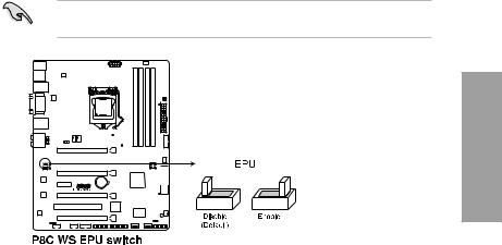
1.EPU switch
Turning this switch to Enable will automatically detect the current PC loadings and intelligently moderate the power consumption.
For ensuring the system performance, turn the switch setting to Enable when the system is powered off.
Chapter 2
ASUS P8C WS |
2-9 |

2.GPU Boost switch
Turning this switch to Enable will automatically optimize the system for fast, yet stable
GPU speed.
For ensuring the system performance, turn the switch setting to Enable when the system is powered off.
2 Chapter
The GPU Boost Switch functions only when you install the DESKTOP CPU that supports onboard graphics.
2-10 |
Chapter 2: Hardware information |

3.MemOK! button
When you install DIMMs that are not compatible with the motherboard, this may cause the system boot failure, and the DRAM_LED near the MemOK switch lights continuously. Simply press the MemOK button until the DRAM_LED starts blinking to patch memory compatibility issues and ensure the system’s successful bootup.
•
•
•
•
•
•
•
•
Chapter 2
Refer to section 2.2.6 Onboard LEDs for the exact location of the DRAM_LED.
The DRAM_LED also lights when the DIMM is not properly installed. Turn off the system and reinstall the DIMM before using the MemOK! function.
The MemOK! button does not function under Windows™ OS environment.
During the tuning process, the system loads and tests failsafe memory settings. It takes about 30 seconds for the system to test one set of failsafe settings. If the test fails, the system reboots and test the next set of failsafe settings. The blinking speed of the DRAM_LED increases, indicating different test processes.
Due to memory tuning requirement, the system automatically reboots when each timing set is tested. If the installed DIMMs still fail to boot after the whole tuning process, the DRAM_LED lights continuously. Replace the DIMMs with ones recommended in the Memory QVL (Qualified Vendors Lists) in this user manual or on the ASUS website at www.asus.com.
If you turn off the computer and replace DIMMs during the tuning process, the system continues memory tuning after turning on the computer. To stop memory tuning, turn off the computer and unplug the power cord for about 5–10 seconds.
If your system fails to boot up due to BIOS overclocking, press the MemOK! button to boot and load the BIOS default settings. A message will appear during POST reminding you that the BIOS has been restored to its default settings.
We recommend that you download and update to the latest BIOS version from the ASUS website at www.asus.com after using the MemOK! function.
ASUS P8C WS |
2-11 |

2.2.6Onboard LEDs
1.POST State LEDs
The POST State LEDs indicate the status of these key components during POST (Power-on-Self Test): CPU, memory modules, VGA card, and hard disk drive. If an error is found, the critical component’s LED stays lit up until the problem is solved.
2 Chapter
2.GPU Boost LED
The GPU Boost LED lights up when the GPU Boost switch is turned to Enable.
|
|
|
|
|
|
|
|
|
|
|
|
|
|
|
|
|
|
|
|
|
|
|
|
|
|
|
|
|
|
|
|
|
|
|
|
|
|
|
|
|
|
|
|
|
|
|
|
|
|
|
|
|
|
|
|
|
|
|
|
|
|
|
|
|
|
|
|
|
|
|
|
|
|
|
|
|
|
|
|
|
|
|
|
|
|
|
|
|
|
|
|
|
|
|
|
|
|
|
|
|
|
|
|
|
|
|
|
|
|
|
|
|
|
|
|
|
|
|
|
|
|
|
|
|
|
|
|
|
|
|
|
|
|
|
|
|
|
|
|
|
|
|
|
|
|
|
|
|
|
|
|
|
|
|
|
|
|
|
|
|
|
|
|
|
|
|
|
|
|
|
|
|
|
|
|
|
|
|
|
|
|
|
|
|
|
|
|
|
|
|
|
|
|
|
|
|
|
|
|
|
|
|
|
|
|
|
|
|
|
|
|
|
|
|
|
|
|
|
|
|
|
|
|
|
|
|
|
|
|
|
|
|
|
|
|
|
|
|
|
|
|
|
|
|
|
|
|
|
|
|
|
|
|
|
|
|
|
|
|
|
|
|
|
|
|
|
|
|
|
|
|
|
|
|
|
|
|
|
|
|
|
|
|
|
|
|
|
|
|
|
|
|
|
|
|
|
|
|
|
|
|
|
|
|
|
|
|
|
|
|
|
|
|
|
|
|
|
|
|
|
|
|
|
|
|
|
|
|
|
|
|
|
|
|
|
|
|
|
|
|
|
|
|
|
|
|
|
|
|
|
|
|
|
|
|
|
|
|
|
|
|
|
|
|
|
|
|
|
|
|
|
|
|
|
|
|
|
|
|
|
|
|
|
|
|
|
|
|
|
|
|
|
|
|
|
|
|
|
|
|
|
|
|
|
|
|
|
|
|
|
|
|
|
|
|
|
|
|
|
|
|
|
|
|
|
|
|
|
|
|
|
|
|
|
|
|
|
|
|
|
|
|
|
|
|
|
|
|
|
|
|
|
|
|
|
|
|
|
|
|
|
|
|
|
|
|
|
|
|
|
|
|
|
|
|
|
|
|
|
|
|
|
|
|
|
|
|
|
|
|
|
|
|
|
|
|
|
|
|
|
|
|
|
|
|
|
|
|
|
|
|
|
|
|
|
|
|
|
|
|
|
|
|
|
|
|
|
|
|
|
|
|
|
|
|
|
|
|
|
|
|
|
|
|
|
|
|
|
|
|
|
|
|
|
|
|
|
|
|
|
|
|
|
|
|
|
|
|
|
|
|
|
|
|
|
|
|
|
|
|
|
|
|
|
|
|
|
|
|
|
|
|
|
|
|
|
|
|
|
|
|
|
|
|
|
|
|
|
|
|
|
|
|
|
|
|
|
|
|
|
|
|
|
|
|
|
|
|
|
|
|
|
|
|
|
|
|
|
|
|
|
|
|
|
|
|
|
|
|
|
|
|
|
|
|
|
|
|
|
|
|
|
|
|
|
|
|
|
|
|
|
|
|
|
|
|
|
|
|
|
|
|
|
|
|
|
|
|
|
|
|
|
|
|
|
|
|
|
|
|
|
|
|
|
|
|
|
|
|
|
|
|
|
|
|
|
|
|
|
|
|
|
|
|
|
|
|
|
|
|
|
|
|
|
|
|
|
|
|
|
|
|
|
|
|
|
|
|
|
|
|
|
|
|
|
|
|
|
|
|
|
|
|
|
|
|
|
|
|
|
|
|
|
|
|
|
|
|
|
|
|
|
|
|
|
|
|
|
|
|
|
|
|
|
|
|
|
|
|
|
|
|
|
|
|
|
|
|
|
|
|
|
|
|
|
|
|
|
|
|
|
|
|
|
|
|
|
|
|
|
|
|
|
|
|
|
|
|
|
|
|
|
|
|
|
|
|
|
|
|
|
|
|
|
|
|
|
|
|
|
|
|
|
2-12 |
|
|
|
|
|
|
|
|
|
|
|
|
|
|
|
|
|
|
|
|
|
|
|
|
|
|
|
|
|
|
|
|
|
|
Chapter 2: Hardware information |
 Loading...