


AMD Advanced Micro Devices AMMC008AWP-150, AMMC008AWP-100I, AMMC004AWP-150, AMMC004AWP-100I, AMMC004AWP-100 Datasheet
...PRELIMINARY
AmMC0XXA
2, 4, or 8 Megabyte 5.0 Volt-only Flash Miniature Card
DISTINCTIVE CHARACTERISTICS
■2, 4, or 8 Mbytes of addressable Flash memory
■5.0 Volt-only, single power supply operation
—Write and read voltage: 5.0 V ± 10%
—No additional supply current required for V PP
■Fast access time
—100 or 150 ns access time
■CMOS low power consumption
—Typical active read current:
70 mA (word mode)
—Typical active erase/write current: 100 mA (word mode)
—Typical standby current:
10μA (8 Mbyte card)
■High write endurance
—Guaranteed minimum 100,000 write/erase cycles per card
—More than 1,000,000 cycles per card typical
■Uniform sector architecture
—64K byte individually useable sectors
—Erase Suspend/Resume increases system level performance
—BUSY# and RESET# signals
■Zero data retention power
—No power required to retain data
■Available in industrial temperature grade (–40 °C to +85°C)
■Miniature Card standard form factor
—True interchangeability
—60-pad connector
—Supports multiple technologies
—Sonic welded stainless steel case
—PCMCIA Type II adapter available
—Selectable byteor word-wide configuration
—Small form factor (38 mm x 33 mm x 3.5 mm)
■60 connection bus
—16-bit data bus
—25-bit address bus
—Easy system integration
—Low cost implementation
—Low cost cards
■Consumer-friendly mechanicals
—User can easily insert and remove card, upgrade memory, and add applications
■Voltage level keying
—Does not allow a 5 V card to plug into a 3 V system and vice versa
—Single power supply design
—System does not need a separate program voltage supply; only one is necessary to read and write
GENERAL DESCRIPTION
The Miniature Card is an expansion card that provides a high-performance, small form factor solution for data and file storage to the portable, handheld market, which includes audio, digital film, wireless, and PDA (Portable Digital Assistant) applications. The Miniature Card provides a low cost, low power, high performance interface for memory cards.
Miniature cards can be easily “snapped” into the back of an electronic system and can be readily removed and replaced by end users. AMD’s 5 V Flash Miniature Cards are manufactured using AMD’s industry leading 5.0 volt-only, single-power-supply Am29F080B and
Am29F017B Flash Memory devices, ensuring high reliability and excellent performance. The Miniature Card is less than 30% of the size of a PCMCIA memory card. Applications include digital voice recorders, pocket PCs and intelligent organizers, smart cellular telephones, voice and data messaging pagers, digital still cameras and portable instrumentation equipment.
The Miniature Card specification will be defined by PCMCIA as of October 1997. The participating association members include major Flash memory vendors and leading consumer electronics OEMs. The goal of the Miniature Card specification is to promote an open, interoperable small-form-factor memory card standard. For more information on the Miniature Card specifica-
This document contains information on a product under development at Advanced Micro Devices. The information |
Publication# 20975 Rev: D Amendment/+1 |
is intended to help you evaluate this product. AMD reserves the right to change or discontinue work on this proposed |
Issue Date: May 1998 |
product without notice. |
|
|

P R E L I M I N A R Y
tion, visit the PCMCIA web site at http://www.pccard.com.
AMD Flash Miniature Cards can be read in either a byte-wide or word-wide mode, which allows for flexible integration into various system platforms. Compatibility is assured at the hardware interface and software interchange specification.
Miniature Card is also designed with low-cost and rugged handling in mind. The card contains virtually no control logic, which keeps cost and power consumption to a minimum. The Miniature Card is packaged in a sonic welded, stainless steel case that guarantees durability, provides good ESD protection and ease of handling.
The Miniature Card has extensive third-party support, including socket and connector solutions, software support from the major FTL software vendors, and PCMCIA adapter solutions and programmer support.
AMD’s Miniature Flash cards can be used for both code and data storage. Since fast random access is possible, code can be directly executed from the card, reducing the amount of system RAM required. In addition. AMD’s Flash technology offers unsurpassed endurance, data retention and reliability, eliminating the need for complex error correction and defect management hardware and software. Each Flash sector provides a minimum of 100,000 cycles, which translates into a typical card life of one million or more cycles.
For more information, please contact your local AMD s a l e s o f f i c e o r v i s i t o u r We b s i t e a t http://www.amd.com/html/products/nvd/nvd.html.
DEFINITIONS
Table 1 lists the terms and definitions that may be used in conjunction with Miniature Card specifications.
|
Table 1. Miniature Card Definitions |
|
|
|
|
Term |
Meaning |
|
|
|
|
AIS |
Acronym for Attribute Information Structure. AIS is a Miniature Card specification for storing |
|
Miniature Card attribute information. |
||
|
||
|
|
|
ESD |
Acronym for Electrostatic Discharge. ESD is part of the Miniature Card physical test. |
|
|
|
|
FAT |
Acronym for File Allocation Table. Using an FAT is a common method for managing files in a |
|
DOS-based system. |
||
|
||
|
|
|
Flash |
A type of non-volatile memory that is both readable and writeable, but requires the media to |
|
be erased before it is rewritten. |
||
|
||
|
|
|
Host |
Any system that incorporates a Miniature Card socket. |
|
|
|
|
|
User Perception: Insertion of the Miniature Card when the host is off. |
|
Insertion, Cold |
Host State: The host would be either off or in sleep mode, no bus activity is occurring, the |
|
host is non-operational by the user. The user inserts the Miniature Card and then presses a |
||
|
||
|
button to turn the host on before the system is operational. |
|
|
|
|
|
User Perception: Insertion of a Miniature Card when the host is running. |
|
Insertion, Hot |
Host State: The host would be in running mode, bus activity is occurring, the host is |
|
operational by the user. The user inserts the card, the host recognizes it, and the host |
||
|
continues to be operational. Note: Hot insertion may require buffering on the host system for |
|
|
proper operation. |
|
|
|
|
|
User Perception: Insertion of a Miniature Card when the host is running. |
|
Insertion, Pseudo Hot |
Host State: The host would be in running mode, bus activity is occurring, the host is |
|
operational by the user. The user inserts the card, the host immediately powers off before the |
||
|
Miniature Card makes contact with the host’s internal bus. The user would then need to press |
|
|
a button to turn the host on for it to become operational. |
|
|
|
|
Interface Signals |
Miniature Card signals that make connection through the 60-pad connector area. |
|
|
|
|
JEDEC |
Acronym for Joint Electronic Device Engineering Council. |
|
|
|
|
Miniature Card Backside |
The side of the Miniature Card that contains the latching mechanism. The backside is |
|
opposite the frontside. |
||
|
||
|
|
|
Miniature Card Bottomside |
The side of the Miniature Card that contains the interface signals. The bottomside is opposite |
|
the topside. |
||
|
||
|
|
|
|
|
|
2 |
AmMC0XXA |

|
P R E L I M I N A R Y |
|
|
Table 1. Miniature Card Definitions (Continued) |
|
|
|
|
Term |
Meaning |
|
|
|
|
Miniature Card Frontside |
The side of the Miniature Card that contains power, insertion, ground, voltage keys, and |
|
alignment notch. The frontside is opposite the backside. |
||
|
||
|
|
|
Miniature Card Topside |
The side of the Miniature Card that contains the Miniature Card label. The topside is opposite |
|
the bottomside. |
||
|
||
|
|
|
PC Card |
A memory or I/O card compatible with the PC Card Standard. |
|
|
|
|
|
The hardware that connects the Miniature Card 60 contact bus to the PC Card 68 pin bus. |
|
PC Card Adapter |
This hardware can be mechanically implemented by following the PC Card Type II |
|
|
specification. |
|
|
|
|
Power/Insertion Signals |
The three signals on the frontside of the Miniature Card that provide ground, power and early |
|
detection of insertion. |
||
|
||
|
|
|
Pull-Ups |
Resistors used to ensure that signals do not float when no device is driving them. |
|
|
|
|
|
User Perception: Removal of a Miniature Card when the host is off. |
|
Removal, Cold |
Host State: The host would either be off or in sleep mode, no bus activity is occurring, the |
|
host is non-operational by the user. User would turn off the host, then remove the Miniature |
||
|
||
|
Card and then press a button to turn the host on for it to become operational again. |
|
|
|
|
|
User Perception: Removal of the Miniature Card when the host is running. |
|
Removal, Hot |
Host State: The host would be in running mode, bus activity is occurring, the host is |
|
operational by the user. User removes the card, the host recognizes the event, and the host |
||
|
||
|
continues to be operational. |
|
|
|
|
|
User Perception: Removal of the Miniature Card when the host is running. |
|
|
Host State: The host would be in running mode, bus activity is occurring, the host is |
|
Removal, Pseudo Hot |
operational by the user. User removes the card, the host recognizes the event, the host |
|
immediately powers off before the Miniature Card removes contact with the host’s internal |
||
|
||
|
bus. The user would then need to press a button to turn the host on for it to be operational |
|
|
again. |
|
|
|
|
Sector |
Usually 64 Kbytes, but depends on device used in the card. In word mode, a sector is 64 |
|
KWords. |
||
|
||
|
|
|
Tuple |
An element of the PC Card Standard CIS that provides card attribute information, and a link |
|
to the next tuple in a string of tuples. |
||
|
||
|
|
|
User Insertable |
All Miniature Cards should be inserted into the host by the user without the need for any |
|
special tools. |
||
|
||
|
|
|
|
This type of Miniature Card can be removed by the user without the need for any special tools. |
|
User Removable |
It contains programs and data that users may want to switch often. The use of this type of |
|
|
card is similar to a floppy disk. |
|
|
|
|
|
This type of Miniature Card must be removed by the user with a special tool. It contains |
|
User Non-Removable |
memory upgrades or boot program that users switches only when they require an upgrade. |
|
|
The use of this type of card is similar to a SIMM memory expansion or boot hard disk. |
|
|
|
|
XIP |
Acronym for eXecute-In-Place, which refers to code that executes directly from a Miniature |
|
Card. |
||
|
||
|
|
AmMC0XXA |
3 |
P R E L I M I N A R Y
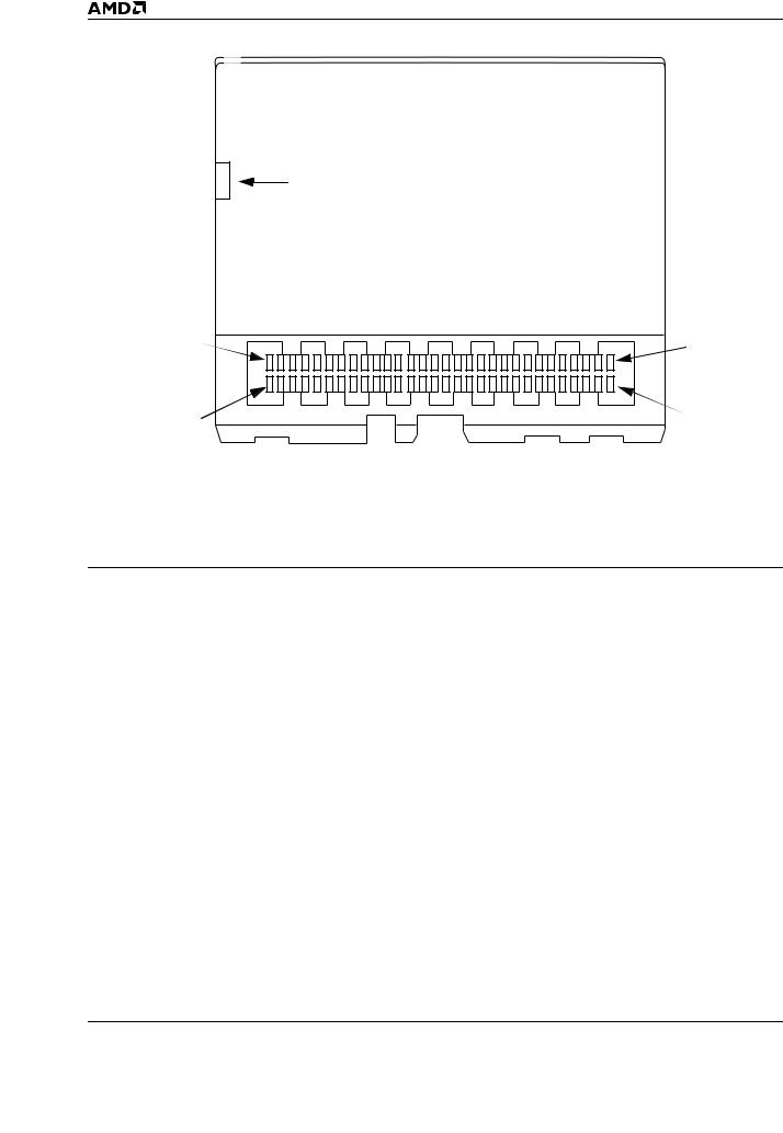
Write Protect Switch (optional)
Pad 60 |
|
|
|
|
|
|
|
|
|
|
|
|
|
|
|
|
|
|
|
|
|
|
Pad 31 |
|
|
|
|
|
|
|
|
|
|
|
|
|
|
|
|
|
|
|
|
|
|||
|
|
|
|
|
|
|
|
|
|
|
|
|
|
|
|
|
|
|
|
|
|
|
|
Pad 30 |
|
|
|
|
|
|
|
|
|
|
|
|
|
|
|
|
|
|
|
|
Pad 1 |
||
|
|
|
|
|
|
|
|
|
|
|
|
|
|
|
|
|
|
|
|
||||
|
|
|
|
3V/5V |
Alignment |
|
|
|
|
|
|
|
|||||||||||
VCC |
|
|
|
|
|
|
CINS# |
GND |
|||||||||||||||
|
|
|
|
|
|
|
|
Key |
|
Notch |
|
|
|
|
|
|
|
20975D-1 |
|||||
|
|
|
|
|
|
|
|
|
|
|
|
|
|
|
|
|
|
|
|
|
|
|
|
Figure 1. Miniature Card Connector (Card Bottom View)
Note: Refer to the Physical Dimensions section for more information. Also refer to the MCIF specification for detailed mechanical information, available on the Web at http://www.mcif.org.
Table 2. AMD Flash Miniature Cards and Flash Devices
Family Part Number |
Density |
No. of Flash Devices |
AMD Flash Memory |
|
|
|
|
AmMC002AWP |
2 Mbyte |
2 |
Am29F080B |
|
|
|
|
AmMC004AWP |
4 Mbyte |
2 |
Am29F017B |
|
|
|
|
AmMC008AWP |
8 Mbyte |
4 |
Am29F017B |
|
|
|
|
4 |
AmMC0XXA |

|
P R E L I M I N A R Y |
BLOCK DIAGRAM |
|
VCC |
VCC |
10K |
10K |
|
VCC |
BUSY# |
RY/BY# |
|
10K |
RESET# |
RESET# to all Flash devices |
WE# |
|
|
|
|
|
|
|
Write Protect |
|
|
|
|
Switch |
|
OE# |
|
|
|
|
D8–D15 |
|
|
|
|
D0–D7 |
|
|
|
|
A0–A24 |
|
|
|
|
VCC |
VCC |
VSS VCC |
||
A0-A20*** D0-D7 |
||||
|
|
CE# |
S0** |
|
100K |
100K |
WE# |
||
|
||||
|
A21 |
OE# |
|
|
|
|
RESET# RY/BY# |
||
CEL# |
CEL0# |
|
|
|
CEH# |
CEH0# |
|
|
|
CEL1# |
|
|
||
|
CEH1# |
VSS VCC |
||
|
|
|||
|
Decoder* |
A0-A20*** D0-D7 |
||
|
|
CE# |
S2** |
|
|
|
WE# |
||
|
|
OE# |
|
|
|
|
RESET# RY/BY# |
||
WE# to all Flash devices
OE# to all Flash devices
VSS VCC
A0-A20*** D8-D15
WE# S1**
OE#
RESET# RY/BY#
VSS VCC
A0-A20*** D8-D15
CE#
WE# S3**
OE#
RESET# RY/BY#
20975D-2
*Decoder used on 8 Mbyte card only. Not used on 2 and 4 Mbyte cards.
**2 Mbyte card: Two Am29F080B devices, S0 and S1
4 Mbyte card: Two Am29F017B devices, S0 and S1
8 Mbyte card: Four Am29F017B devices, S0...S3
***A0–A19 on 2 Mbyte card; A0–A20 on 4 and 8 Mbyte cards.
Note: On the 2 Mbyte card, A20–A24 are not connected. On the 4 Mbyte cards, A21–A24 are not connected. On the 8 Mbyte cards, A22-A24 are not connected. Connections not shown in this diagram are not connected internally.
AmMC0XXA |
5 |

P R E L I M I N A R Y
MINIATURE CARD PAD ASSIGNMENTS
A0–A24
Address A0 to A24 are the address bus lines that can address up to 32 Mwords (64 Mbytes). The address lines are word addressed. The Miniature Card specification does not require the Miniature Card to decode the upper address lines. A 2 Mbyte Miniature Card that does not decode the upper address lines would repeat its address space every 2 Mbytes. Address 0h would access the same physical location as 200000h, 400000h, 600000h, etc. On the 2 Mbyte cards, A20– A24 are not connected. On the 4 Mbyte cards, A21– A24 are not connected. On the 8 Mbyte cards, A22– A24 are not connected.
D0–D15
Data lines D0 through D15 constitute the data bus. The data bus is composed of two bytes; the low byte is D0– D7 and the high byte is D8–D15. These lines are tristated when OE# is high.
OE#
OE# indicates to the card that the current bus cycle is a read cycle. The output enable access time (tOE) is the delay from the falling edge of OE# to valid data at the output pins (assuming the addresses have been stable for at least tACC – tOE time).
WE#
WE# indicates to the card that the current bus cycle is a write cycle. The falling edge of WE# latches address information and the rising edge latches data/command information.
VS1#
Voltage Sense 1 signal. This signal is left open or not connected.
VS2#
Voltage Sense 2 signal. This signal is left open or not connected.
CEL#
CEL# enables the low byte of the data bus (D0–D7) on the card.
CEH#
CEH# enables the high byte of the data bus (D8–D15) on the card.
RESET#
RESET# controls card initialization. When RESET# transitions from a low state to a high state, the Miniature Card resets to the Read state.
BUSY#
BUSY# is a signal generated by the card to indicate the status of operations within the Miniature Card. When BUSY# is high, the Miniature Card is ready to accept the next command from the host. When BUSY# is low, the Miniature Card is busy and unable to accept most data operations from the host. In Flash Miniature Cards the BUSY# signal is tied to the components’ RY/BY# signal.
CD#
CD# is a grounded interface signal. After a Miniature Card has been inserted, CD# will be forced low. The card detect signal is located in the center of the second row of interface signals, and should be one of the last interface signals to connect to the host. Do not confuse CD# with CINS#.
CINS#
CINS# is a grounded signal on the front of the Miniature Card that is used for early detection of a card insertion. CINS# makes contact on the host when the front of the card is inserted into the socket, before the interface signals connect.
BS8#
The BS8# (Bus size 8) signal indicates to the Miniature Card that the host has an 8-bit bus. AMD Flash Miniature Cards ignore this signal. An 8-bit host must connect its D0–D7 data lines to D8–D15 on the Miniature Card to retrieve the upper (odd) byte.
GND
Ground
VCC
Vcc is used to supply power to the card.
NC
No connect
RFU
Reserved for future use
6 |
AmMC0XXA |
P R E L I M I N A R Y
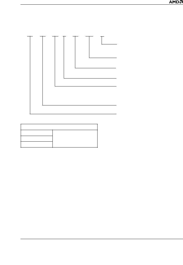
ORDERING INFORMATION
Standard Products
AMD standard products are available in several packages and operating ranges. The order number (Valid Combination) is formed by a combination of the following:
AM |
MC 008 A WP |
-100 |
I |
Valid Combinations
AmMC002AWP
AmMC004AWP |
-100, -100I, -150 |
AmMC008AWP
TEMPERATURE RANGE
Blank = Commercial (0°C to +70°C)
I = Industrial (–40°C to +85°C)
SPEED OPTION
See Valid Combinations below
WRITE PROTECT SWITCH OPTION
WP = Switch installed
REVISION LEVEL
MEMORY CARD DENSITY
002 = 2 Megabyte Card
004 = 4 Megabyte Card
008 = 8 Megabyte Card
MINIATURE CARD
AMD
Valid Combinations
Valid Combinations list configurations planned to be supported in volume for this device. Consult the local AMD sales office to confirm availability of specific valid combinations and to check on newly released combinations.
AmMC0XXA |
7 |

P R E L I M I N A R Y
INTERFACE SIGNAL ASSIGNMENTS
Pad Number |
Signal Name |
Pad Number |
Signal Name |
Pad Number |
Signal Name |
|
|
|
|
|
|
1 |
A18 |
21 |
D12 |
41 |
A4 |
|
|
|
|
|
|
2 |
A16 |
22 |
D10 |
42 |
CEL# |
|
|
|
|
|
|
3 |
A14 |
23 |
D9 |
43 |
A1 |
|
|
|
|
|
|
4 |
NC |
24 |
D0 |
44 |
NC |
|
|
|
|
|
|
5 |
CEH# |
25 |
D2 |
45 |
NC |
|
|
|
|
|
|
6 |
A11 |
26 |
D4 |
46 |
CD# |
|
|
|
|
|
|
7 |
A9 |
27 |
RFU |
47 |
A21 |
|
|
|
|
|
|
8 |
A8 |
28 |
D7 |
48 |
BUSY# |
|
|
|
|
|
|
9 |
A6 |
29 |
NC |
49 |
WE# |
|
|
|
|
|
|
10 |
A5 |
30 |
NC |
50 |
D14 |
|
|
|
|
|
|
11 |
A3 |
31 |
A19 |
51 |
RFU |
|
|
|
|
|
|
12 |
A2 |
32 |
A17 |
52 |
D11 |
|
|
|
|
|
|
13 |
A0 |
33 |
A15 |
53 |
VS2# |
|
|
|
|
|
|
14 |
NC |
34 |
A13 |
54 |
D8 |
|
|
|
|
|
|
15 |
A24 |
35 |
A12 |
55 |
D1 |
|
|
|
|
|
|
16 |
A23 |
36 |
RESET# |
56 |
D3 |
|
|
|
|
|
|
17 |
A22 |
37 |
A10 |
57 |
D5 |
|
|
|
|
|
|
18 |
OE# |
38 |
VS1# |
58 |
D6 |
|
|
|
|
|
|
19 |
D15 |
39 |
A7 |
59 |
RFU |
|
|
|
|
|
|
20 |
D13 |
40 |
BS8# |
60 |
A20 |
|
|
|
|
|
|
Note: NC = No Connect; RFU = Reserved for Future Use.
FLASH MINIATURE CARD OPERATIONS
Voltage Sensing
AMD Miniature Cards provide two voltage sense signals for hosts that support multiple voltages. The multivoltage host can sense the voltage level of the Miniature Card and power up the card at that voltage. See Table 3 for a description of the voltage sense signals.
In addition to the voltage sense pins, there are also mechanical voltage keys on the Miniature Card that
ensure the card can only be inserted into host systems that can supply the proper voltage levels to the card. Refer to Section 4.1.2 in the Miniature Card specification for more information on mechanical keying.
Table 3. Voltage Sense Signals
Miniature Card |
|
|
Power-Up Voltage |
VS1# |
VS2# |
|
|
|
5 Volt-only |
Open |
Open |
|
|
|
8 |
AmMC0XXA |

P R E L I M I N A R Y
Data Accesses
The Miniature Card has a 16-bit data bus that can accommodate word or byte accesses. By individually asserting CEL# and CEH#, a host can access either byte. However, byte swapping (moving the high byte data to the low byte) is not supported.
Figure 2 shows the connections between the host and Miniature Card. The host system address lines range from A0-A25, whereas the Miniature Card address
lines range from A0–A24. On the host, A0 and the byte/word line are sent to a decoder and output to CEL# and CEH# on the Miniature Card. These two bits enable a single device for byte accesses and two devices for word accesses, as shown by the decoder truth table in Figure 2. Again, the Miniature Card address lines do not receive input from host address bit A0. In this document, all address references are card addresses, unless otherwise noted. Table 4 shows the read/write modes for Miniature Cards.
|
|
|
|
|
|
|
|
|
|
|
|
|
|
|
|
|
A0 |
Byte/Word |
|
|
|||||
|
|
|
|
|
|
|
|
|
|
|
|
|
|
|
|
|
|
|
|
|
|
|
|
|
|
|
|
|
|
|
|
|
|
|
|
|
|
|
|
|
|
|
|
|
|
|
|
|
|
|
|
|
|
|
|
|
|
|
|
|
|
|
|
|
|
|
|
|
|
|
Decoder |
|
|
||||
|
|
|
|
|
|
|
|
|
|
|
|
|
|
|
|
|
|
|
Decoder Truth Table |
|
|
||||
|
|
|
|
|
|
|
|
|
|
|
|
|
|
|
|
|
|
Input |
|
Output |
|
||||
|
|
|
|
|
|
|
|
|
|
|
|
|
|
|
|
|
|
|
|
|
|
|
|
|
|
|
|
|
|
|
|
|
|
|
|
|
|
|
|
|
|
|
|
A0 |
B/W |
|
CEL |
|
CEH# |
|
|
|
|
|
|
|
|
|
|
|
|
|
|
|
|
|
|
|
0 |
0 |
|
0 |
|
0 |
|
||
|
|
|
|
|
|
|
|
|
|
|
|
|
|
|
|
|
|
|
|
|
|
|
|
||
|
|
|
|
|
|
|
|
|
|
|
|
|
|
|
|
|
0 |
1 |
|
0 |
|
1 |
|
||
|
|
|
|
|
|
|
|
|
|
|
Host Bus |
|
|
|
|
|
|
|
|
|
|
|
|
||
|
|
|
|
|
|
|
|
|
|
|
|
|
|
|
|
1 |
0 |
|
0 |
|
0 |
|
|||
|
|
|
|
|
|
|
|
|
|
|
|
|
|
|
|
|
|
|
|
|
|
|
|
||
Host |
A25 |
A24 |
A23 |
A22 |
A21 |
A2 |
A1 |
|
1 |
1 |
|
1 |
|
0 |
|
||||||||||
|
|
|
|
|
|
|
|
|
|
||||||||||||||||
|
|
|
|
|
|
|
|
|
|
||||||||||||||||
|
|
|
|
|
|
|
|
|
|
|
|
|
|
|
|
|
|
|
|
|
|
|
|
|
|
|
|
|
|
|
|
|
|
|
|
|
|
|
|
|
|
|
|
|
|
|
|
|
|
|
|
|
|
|
|
|
|
|
|
|
|
60-Pad Connector |
|
|
|
|
|
|
|
|
|
|
|
|
|
|
|
|
|
|
|
|
|
|
|
|
|
|
|
|
|
|
|
|
|
|
|
|
|
|
|
|
|
Card |
|
|
|
|
|
|
|
|
|
|
|
|
|
|
|
|
|
|
|
|
|
|
|
|
|
A24*** |
A23*** |
A22*** |
A21** |
A20* |
A1 |
A0 |
|
CEL# |
CEH# |
|
|
|
|
||||||||||||
20975D-3
Card Bus
*Not connected on 2 Mbyte card
**Not connected on 2 and 4 Mbyte card
***Not connected
Figure 2. Host/Card Address Connections
AmMC0XXA |
9 |

P R E L I M I N A R Y
Table 4. Miniature Card Read/Write Modes
Function |
CEH# |
CEL# |
WE# |
OE# |
D8–D15 |
D0–D7 |
|
|
|
|
|
|
|
Read Mode |
|
|
|
|
|
|
|
|
|
|
|
|
|
Standby |
H |
H |
X |
X |
High-Z |
High-Z |
|
|
|
|
|
|
|
Word Access |
L |
L |
H |
L |
High Byte Data |
Low Byte Data |
|
|
|
|
|
|
|
Low Byte Access |
H |
L |
H |
L |
High-Z |
Low Byte Data |
|
|
|
|
|
|
|
High Byte Access |
L |
H |
H |
L |
High Byte Data |
High-Z |
|
|
|
|
|
|
|
Write Mode |
|
|
|
|
|
|
|
|
|
|
|
|
|
Standby |
H |
H |
X |
X |
High-Z |
High-Z |
|
|
|
|
|
|
|
Word Access |
L |
L |
L |
H |
High Byte Data |
Low Byte Data |
|
|
|
|
|
|
|
Low Byte Access |
H |
L |
L |
H |
High-Z |
Low Byte Data |
|
|
|
|
|
|
|
High Byte Access |
L |
H |
L |
H |
High Byte Data |
High-Z |
|
|
|
|
|
|
|
Notes:
1.Unlisted access combinations are invalid and may return unexpected results.
2.X indicates a Don’t Care value.
Erase Operations
The AMD Flash Miniature Card is organized as an array of individual devices. On the 2 Mbyte Miniature Card, each Am29F080B device contains sixteen 64 Kbyte sectors, for a total of 1 Mbyte of memory space per device. On 4 and 8 Mbyte Miniature Cards, each Am29F017B device contains thirty-two 64 Kbyte sectors, for a total of 2 Mbytes of memory space per device.
Flash technology allows any logical “1” data bit to be programmed to a logical “0”. The only way to reset bits to a logical “1” is to erase that entire memory sector or memory device. Once a memory sector or memory device is erased, any address location may be programmed. Two or more devices may be erased concurrently when additional ICC current is supplied to the card. However, erasing more than two devices concurrently is not typical in battery-powered applications, but may take place during procedures such as card testing.
Since erase commands operate on entire sectors or devices, the host should track the affected memory addresses; for example, by determining the sector size and device size and calculating the corresponding addresses.
Erase operations can be performed in several ways:
■Erase a single sector or multiple sectors in a device
■Erase a sector pair
■Erase multiple device pairs *
■Erase the entire card *
* This operation is only feasible in solutions capable of supplying more than the specified miniature card supply current requirement (150 mA) per system. Each
AMD Flash memory device pair will require a maximum of 120 mA supply current.
The common memory space data contents are altered in a similar manner as writing to individual Flash memory devices. An on-card address decoder activates the appropriate Flash device in the memory array. Each device internally latches address and data during write cycles. Refer to Table 4.
Word-Wide Operations
The AMD Miniature Card provide the flexibility to operate on data in a byte-wide or word-wide format. In word-wide operations, the low bytes are controlled with CEL#. The high bytes are controlled with CEH#. Refer to the block diagram for more information.
Byte-Wide Operations
Byte-wide data is available for read and write operations (CEL# = 0, CEH# = 1). Even and odd bytes are stored in separate memory devices (for example, S0 and S1) and are accessed by controlling CEL# and CEH#. The even byte is the low order byte and the odd byte is the high order byte of a 16-bit word.
Each memory sector or device pair must be addressed separately for erase operations. Refer to the block diagram for more information.
Card Detection
Each CD# (output) pin should be detected by the host system to determine if the memory card is adequately seated in the socket. CD# and CINS# are internally tied to ground. If both bits are not detected, the system should indicate that the card must be re-inserted.
10 |
AmMC0XXA |
P R E L I M I N A R Y
Data Protection
An optional mechanical write protect switch provides user-initiated write protection. When this switch is activated, WE# is internally forced high. The Flash memory command register is disabled from accepting any write commands. This prevents the card from responding to any commands (for example, an Autoselect command). See Figure 3.
Write Enabled
Write Disabled
20975D-4
Figure 3. Write Protect Switch
(Card Right Side View)
In addition to card-level data protection, AMD Flash Miniature Cards offer several device-level data protection features.
Device-Level Data Protection
AMD Flash memory devices offer protection against accidental erasure or programming caused by spurious system level signals that may exist during power transitions. During power up, each device automatically resets the internal state machine to the read mode. The control register architecture allows alteration of the memory contents only occurs after successful completion of specific multi-bus cycle command sequences.
AMD Flash memory devices also incorporate the following features to prevent inadvertent write cycles resulting from VC C power-up and power-down transitions or system noise.
Low VCC Write Inhibit
To avoid initiation of a write cycle during VCC powerup and power-down, the AMD memory devices in the Miniature Card lock out write cycles for VCC < VLKO (see “DC Characteristics” on page 25 for voltages). When VCC < VLKO, the command register is disabled, all internal program/erase circuits are disabled, and the device resets to the read mode. These memory devices ignore all writes until VCC > VLKO. The user must ensure that the control pins
are in the correct logical state when VCC > VLKO to prevent unintentional writes.
Write Pulse “Glitch” Protection
Noise pulses of less than 5 ns (typical) on OE#, CE#, or WE# will neither initiate a write cycle nor change the command registers.
Logical Inhibit
Writing is inhibited by holding any one of OE# = VIL, CE# = VIH, or WE# = VIH. To initiate a write cycle CE# and WE# must be a logical zero while OE# is a logical one.
Power-Up Write Inhibit
Power-up of the device with CE# = WE# = VIL and OE# = VIH will not accept commands on the rising edge of WE#. The internal state machine is automatically reset to the read mode on power-up.
Read Mode
Two Card Enable (CE#) pins are available on the memory card. Both CE# pins must be active low for word-wide read accesses. Only one CE# is required for byte-wide accesses. The CE# pins select and determine when to apply power to the high-byte and lowbyte memory devices. The Output Enable (OE#) controls gating accessed data from the memory device outputs.
The Miniature card automatically powers up in the read/reset state. In this case, a command sequence is not required to read data. Standard microprocessor read cycles will retrieve array data. This default value ensures that no spurious alteration of the memory content occurs during the power transition. Refer to the AC Read Characteristics and Waveforms for the specific timing parameters.
Output Disable
Data outputs from the card are disabled when OE# is at a logic-high level. Under this condition, outputs are in the high-impedance state.
Standby Operations
Byte-wide read accesses only require half of the read/write output buffer (x16) to be active. In addition, only one memory device is active within either the high order or low order bank. Activation of the appropriate half of the output buffer is controlled by the combination of both CE# pins. The CE# pins also control power to the high and low-order banks of memory. Outputs of the memory bank not selected are placed in the high impedance state. The individual memory device is activated by the address decoders. The other memory devices operate in standby. An active memory device continues to draw power until completion of a write or erase operation if the card is de-selected in the process of one of these operations.
AmMC0XXA |
11 |

P R E L I M I N A R Y
Autoselect Operation
A host system or external card reader/writer can determine the on-card manufacturer and device I.D. codes. Codes are available after writing the 90h command to the command register of a memory device, as shown in Tables 5 through 10. When the autoselect command is issued to card address 00000h, the Miniature Card returns the manufacturer I.D. If the autoselect command is issued to card address 00001h, the Miniature Card provides the device I.D.
To ter minate the Auto Select operation, the Read/Reset command sequence must be written to the same device. The Autoselect command operates only if the card is not write protected.
Sector Group Protection
Sector group protection can be used to permanently disable program and erase operations in any combination of sector groups on the Flash memory components used in AMD Miniature Cards. Each sector group consists of four adjacent sectors within each device. The pattern begins at SA0: SA0–3, SA4–7, SA8–11, and so on. This protection must be performed prior to manufacturing the Miniature Cards. None of the sector groups are protected on the standard Miniature Card product offerings.
The host system must compensate for these protected sector groups by determining their locations, then ignoring those locations for reading and writing data. To
determine whether a sector group is protected, the system would write the first three cycles of the Autoselect command, then on the fourth cycle, read at the address (SA)02h, where SA is the sector address (see Tables 11 and 12) within an individual device. A protected sector group produces “01h”, and an unprotected sector group produces “00h”.
Write Operations
Write and erase operations are valid only when VCC is above 4.5 V. This activates the state machine of an addressed memory device. The command register is a latch which saves address, commands, and data information used by the state machine and memory array.
When Write Enable (WE#) and appropriate CE# signals are at a logic-level low, and Output Enable (OE#) is at a logic-high, the command register is enabled for write operations. The falling edge of WE# latches address information and the rising edge latches data/command information.
Write or erase operations are performed by writing appropriate data patterns to the command register of accessed Flash memory devices.
The byte-wide commands are defined in Tables 6, 7, 9, and 10; word-wide commands are defined in Tables 5 and 8. Note that the Erase Suspend (B0h) and Erase Resume (30h) commands are valid only while the Sector Erase operation is in progress.
12 |
AmMC0XXA |
 Loading...