


LE-366
AMD Geode TM
LX800 3.5” Embeded Board
User’s Manual

LE-366 User’s Manual
Copyright
Copyright 2006. All rights reserved. This document is copyrighted and all rights are reserved. The information in this document is subject to change without prior notice to make improvements to the products.
This document contains proprietary information and protected by copyright. No part of this document may be reproduced, copied, or translated in any form or any means without prior written permission of the manufacturer.
All trademarks and/or registered trademarks contains in this document are property of their respective owners.
Disclaimer
The company shall not be liable for any incidental or consequential damages resulting from the performance or use of this product.
The company does not issue a warranty of any kind, express or implied, including without limitation implied warranties of merchantability or fitness for a particular purpose.
The company has the right to revise the manual or include changes in the specifications of the product described within it at any time without notice and without obligation to notify any person of such revision or changes.
Trademark
All trademarks are the property of their respective holders.
Any questions please visit our website at http://wwwUT .commell.com.twTU
-1-

LE-366 User’s Manual
Packing List
Please check the package before you starting setup the system.
Hardware:
LE-366 series motherboard x 1
Cable Kit:
44pin
44pin |
40pin |
Power Cable x 1
44-pin ATA33 IDE Cable x 1
Floppy Cable x 1
DC_IN Power Cable x 1 |
PS2 keyboard & mouse cable |
RS232 Cable x 1 |
USB Cable x 1 |
|
Printed Matters:
User’s Manual x 1
Driver CD x 1
-2-
LE-366 User’s Manual |
|
|
|
Index |
|
Chapter 1 <Introduction>.................................................................... |
6 |
|
1.1 |
<Product Overview> ............................................................................... |
6 |
1.2 |
<Product Specification> ......................................................................... |
7 |
1.3 |
<Mechanical Drawing> ........................................................................... |
9 |
1.4 |
<Block Diagram>................................................................................... |
10 |
2.1<Connector Location> ........................................................................... |
11 |
|
|
2.1.1 <Connector Reference> ............................................................. |
13 |
|
2.1.2 <External Connector>................................................................. |
13 |
2.2 |
<CPU and Memory Setup> ................................................................... |
14 |
|
2.2.1 <CPU Setup> ............................................................................. |
14 |
|
2.2.2 <Memory Setup> ........................................................................ |
14 |
2.3 |
<Enhanced IDE & CF Interface> .......................................................... |
16 |
2.4 |
<Floppy Port> ........................................................................................ |
17 |
|
2.4.1 <Analog VGA Interface> ............................................................ |
18 |
|
2.4.2 <Digital Display>......................................................................... |
19 |
2.5 |
<GPIO Interface> ................................................................................... |
24 |
2.6 |
<Serial Port Jumper Setting >.............................................................. |
25 |
|
2.6.1 <Power Input> ............................................................................ |
26 |
|
2.6.2 <Power Output> ......................................................................... |
26 |
Chapter 3 <BIOS Setup>.................................................................... |
30 |
|
Appendix A <I/O Port Pin Assignment>................................. |
32 |
|
A.1 <IDE Port> ............................................................................................. |
32 |
|
A.2 <Floppy Port>........................................................................................ |
33 |
|
A.3 <Serial Port>.......................................................................................... |
33 |
|
A.4 <CRT Port>............................................................................................ |
34 |
|
A.5 <LAN Port>............................................................................................ |
34 |
|
A.6 < USB Port >.......................................................................................... |
34 |
|
|
-3- |
|
LE-366 User’s Manual |
|
|
A.7 <PS/2 Keyboard & Mouse Port>.......................................................... |
35 |
|
Appendix B <Flash BIOS>................................................................ |
37 |
|
B.1 |
BIOS Auto Flash Tool................................................................ |
37 |
B.2 |
Flash Method.............................................................................. |
37 |
Appendix C <System Resources> ............................................. |
38 |
|
Appendix D <Programming GPIO’s> ....................................... |
42 |
|
Contact Information.............................................................................. |
45 |
|
-4-
LE-366 User’s Manual
(The Page is Left For Blank)
-5-
LE-366 User’s Manual
Chapter 1 <Introduction>
1.1 <Product Overview>
LE-366 is the Mini-ITX motherboard with AMD Geode LX800 platform, with onboard VGA, AC97 audio, GIGA LAN interface. Based on the AMD Geode LX800 processor, the board provides many advanced features for reduced power consumption, fan-less design and high cost/price rate of production.
Low Power Consumption
Based on the AMD Geode LX800@500MHz processor onboard, it only takes up to 3.8W at maximum powering, and is completely suitable for fan-less design. Without any cooling fan onboard, it can avoid the heat problem when the cooler failed in accidence.
Onboard TFT/LVDS LCD interface
Based on the AMD Geode LX800@500Mhz of integrated graphics and 18-bit LVDS interfaces.
Embedded Component
Due to the low profile design, the board provides CF card socket for flash disk with porting embedded OS and up to DDR SDRAM.
Single Voltage Input
The board only requires DC 12V input. User’s can easily connect the board with an adapter without the huge power supply.
-6-

LE-366 User’s Manual
1.2 <Product Specification>
General Specification
Form Factor |
145 mm x 102 mm (5.7” x 4”) |
|
CPU |
Up to AMD Geode LX 800 Processor |
|
Memory |
One So-DIMM slot support DDR 266/333/400 MHz SDRAM up to |
|
|
1GB |
|
Chipset |
AMD Geode CS5536 |
|
BIOS |
Phoenix-Award 4Mb PnP Flash |
|
Green Function |
ACPI 1.0 and APM 1.2 compliant |
|
Watchdog Timer |
PIT (Programmable Interval Timer) with 3 channels |
|
Real Time Clock |
AMD Geode CS5536 built in RTC with Lithium |
|
Enhanced IDE |
UDMA ATA 33 ATA IDE connection |
|
Multi-I/O Port |
|
|
Chipset |
AMD Geode CS5536+Winbond W83627HG |
|
Serial Port |
1 external RS-232 port (COM1) |
|
|
1 internal RS-232/422/485 port (COM2) |
|
USB Port |
2 external USB 2.0 ports |
|
|
2 internal USB 2.0 ports |
|
Floppy Port |
One slim type Floppy port |
|
K/B & Mouse |
1 PS 2 port |
|
GPIO |
One 12-pin Digital I/O connector with 8-bit programmable I/O |
|
|
interface |
|
VGA Display Interface |
|
|
Chipset |
Built in Geode LX Processor High performance 2D graphics |
|
|
controller |
|
Memory |
Shared system memory up to 4MB |
|
Frame Buffer |
Up to 256MB shared with system memory |
|
Display Type |
Support 1920x1440 in CRT mode and 1600x1200 in TFT mode |
|
|
VESA 1.1 and 2.0 VIP/VDA support |
|
Connector |
External DB15 female connector on rear I/O panel |
|
|
Onboard 30-pin LVDS connector |
|
Ethernet Interface |
|
|
Controller |
1 x Realtek RTL8110S-32 Gigabit Ethernet controller |
|
Type |
Triple speed 10/100/1000Base-T |
|
|
Auto-switching Fast Ethernet |
|
|
Full duplex, IEEE802.3U compliant |
|
Connector |
One External RJ45 connector with LED on rear I/O panel |
|
Audio Interface |
|
|
Chipset |
Realtek ® ALC203 AC97 Audio compliance |
|
Interface |
2 channels sound output |
|
|
-7- |
|
|
|
|

LE-366 User’s Manual
Connector External Audio phone jack for Line-out and MIC-in. Onboard audio connector with pin header
Expansive Interface
PCI |
1 |
Mini-PCI slot V2.2 33/66 MHz |
|
1 |
Compact Flash (optional) |
Power and Environment |
||
Power Requirement |
12V DC Jack power connector |
|
Temperature |
Operating temperature with 0 ~60 (32 ~ 140 ) |
|
|
Storage temperature with 20 ~ 80 (-68 ~ 176 ) |
|
Ordering Code |
|
|
LE-366 |
AMD LX800 processor Mini-ITX with onboard VGA, GigaLAN, |
|
|
RS232, USB2.0, Audio, LCD and DDR DIMM |
|
The specifications may be different as the actual production.
For further product information please visit the website at http://wwwTU .commell.com.twUT
-8-

LE-366 User’s Manual
1.3 <Mechanical Drawing>
‘
‘
‘
‘
‘
‘
-9-
LE-366 User’s Manual
1.4 <Block Diagram>
CRT |
16Mbx16 |
|
DDR DIMM |
||
|
||
|
AMD Geode |
|
LVDS |
LX Processor |
|
|
PCI BUS/33Mhz MiniPCI
SLOT
IDE X 1 |
RealTek |
LAN1 |
RTL8110SB |
||
CFD X 1 |
AMD Geode |
|
|
CS5536 |
|
4 x USB2.0 ports |
ALC203 |
AUDIO |
|
|
JACK |
83627HF
Flash
KB & MS BIOS (SST FWH)
Digital I/O
Slim FDD
COM1
COM2
-10-

LE-366 User’s Manual
Chapter 2 <Hardware Setup>
2.1<Connector Location>
|
|
CN1 |
J8 |
CN9 P2 |
CN4 |
USB2 |
|
|||
P1 |
JP3 CN7 |
|
LAN1 |
|||||||
|
|
USB1 |
||||||||
|
|
|
|
|
|
|
|
|
|
|
|
|
|
|
|
|
|
|
|
|
|
|
|
|
|
|
|
|
|
|
|
|
|
|
|
|
|
|
|
|
|
|
|
JP2
FDD1
MPCI1
CN8
CN3
J4
JP1 CN2 |
J7 |
J6 |
MIC1 JSPK1 |
LAN1 |
USB1 |
PS2 |
COM |
VGA |
MIC |
LINE OUT |
-11-
LE-366 User’s Manual
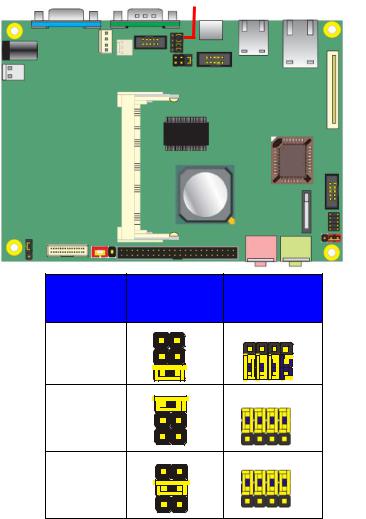
<Jumper Reference>
Jumper |
Function |
JP1 |
LVDS Panel Voltage Selection (+5V / + 3.3V) |
JP2 |
COM2 RS232/422/485 Select |
JP3 |
COM2 RS232/422/485 Select |
J4 |
Clear CMOS Selection |
J7 |
CFD Master/Slave Selection |
JP3
JP2 
J4
JP1 |
J7 |
|
|
|
|
|
|
|
JP2 |
|
JP3 |
|
RS-232 |
5 |
6 |
3 |
12 |
|
|
|
|||
|
|
1 |
2 |
1 |
10 |
|
RS-485 |
|
|
|
|
|
RS-422 |
|
|
|
|
-12-

LE-366 User’s Manual
2.1.1 <Connector Reference>
Connector |
Function |
Remark |
CN1 |
VGA Display / Audio Connector |
Standard |
CN2 |
Front Audio Connector LVDS Connector |
Slim |
CN3 |
Front Panel Connector |
Slim |
CN4 |
COM2 RS-232 / RS-422 / RS-485 Connector |
Standard |
CN7 |
PS2 Keyboard / Mouse Connector |
Standard |
CN8 |
GPIO Connector |
Standard |
CN9 |
SYSTEM Fan Connector |
Standard |
J6 |
EIDE Connector |
Standard |
J8 |
Little 4-Pin Power connector |
Standard |
USB2 |
USB2 Connector |
Standard |
FDD1 |
Slim Floppy Connector |
Standard |
P2 |
COM1 RS-232 Connector |
Standard |
LAN1 |
Gigabit LAN / USB Connector |
Standard |
MPCI1 |
Mini-PCI Slot |
Standard |
CFD1 |
Compact Flash Slot |
Standard |
J1 |
SO-DIMM Slot |
Slim |
P1 |
12V DC Connector |
Standard |
MIC1 |
Microphone Jack |
Standard |
JSPK1 |
Speaker out Jack |
Standard |
2.1.2 <External Connector>
Connector |
|
|
|
Remark |
LAN1 |
|
1 external RJ – 45 ports with LED |
|
Standard |
USB1 |
|
2 external USB 2.0 ports |
|
Standard |
|
|
2 internal USB 2.0 ports |
|
|
PS2 |
1 PS / 2 ports |
|
Standard |
|
COM |
1 external RS – 232 port (COM1) |
|
Standard |
|
|
|
1 internal RS – 232 / 422 / 485 port (COM2) |
|
|
VGA |
1 VGA port |
|
Standard |
|
AUDIO |
2 external jack for MIC – In / Line – Out |
|
Standard |
|
-13-
 Loading...