


RS780

AMD RS780 Series
RS780G+SB700 Chipset
Socket AM2/AM2+ Processor Mainboard
User’s Manual
Rev: 1.0, May 2008
P/N: 88EN780GA0

Disclaimer
The intellectual property of this manual belongs to our company. The ownership of all of the
products, including accessories and software etc. belong to our company. No one is permitted to
copy, change, or translate without our written permission.
We compiled this manual based on our careful attitude, but we can not guarantee the accuracy
of the contents. This manual is purely technical documentation, without any hint or other
meanings, and we won't commit users' misunderstanding of the typesetting error.
Our products are in continuous improvement and updating, Therefore, we retain the right that
we won't give notice to the users in future.
Copyright
All of the trademark in this manual belong to their own registered company.
All of the products name is only for identication, its title belongs to its manufacturer or brand
owner.

Table of Contents
Chapter 1 Introduction ...........................................................................................
1.1 Package Checklist ...............................................................................................................
1.2 Specications ......................................................................................................................
1.3 Mainboard Layout ...............................................................................................................
1.4 Connecting Rear Panel I/O Devices ............................................................................. 6
Chapter 2 Hardware Setup ...................................................................................... 7
2.1 Choosing a Computer Chassis ..............................................................................................
2.2 Installing Mainboard ............................................................................................................
2.3 Installation of the CPU and CPU Cooler................................................................................
2.3.1 Installation of the CPU ............................................................................................................
2.3.2 Installation of the CPU Cooler ..................................................................................................
2.4 Installation of Memory Modules............................................................................................
2.5 Connecting Peripheral Devices............................................................................................. 10
2.5.1 Floppy and IDE Disk Drive Connectors ...................................................................................... 10
2.5.2 Serial ATA Connectors ............................................................................................................. 10
2.5.3 PCI and PCI Express slots ........................................................................................................ 10
8
8
9
Chapter 3 Jumpers & Headers Setup .................................................................... 11
3.1 Checking Jumper Settings .................................................................................................. 11
3.2 CMOS Memory Clearing Header .......................................................................................... 11
3.3 Keyboard Power Function ................................................................................................... 11
3.4 FAN Power Connectors ....................................................................................................... 12
3.5 Front Panel Switches & Indicators Headers ..........................................................................12
3.6 Additional USB Port Headers ...............................................................................................13
3.7 Front Panel Audio Connection Header....................................................................................13
3.8 Serial Port Header(JCOM1)..................................................................................................
3.9 JDVI Jumper....................................................................................................................... 14
3.10 S/PDIF out connection Header............................................................................................15
3.11 ATX Power Input Connectors .............................................................................................15
1
Chapter 4 BIOS Setup Utility ................................................................................. 16
4.1 About BIOS Setup ............................................................................................................. 16
4.2 To Run BIOS Setup ........................................................................................................... 16
4.3 About CMOS...................................................................................................................... 16
4.4 The POST (Power On Self Test)........................................................................................... 16
4.5 BIOS Setup — CMOS Setup Utility.....................................................................................
4.5.1 CMOS Setup Utility ................................................................................................................ 17
4.5.2 Control Keys ........................................................................................................................ 18
4.5.3 Advanced Setting ................................................................................................................. 19
4.5.4 Advanced PCI/PNP Setting..................................................................................................... 22
4.5.5 Boot Setting.......................................................................................................................... 23
4.5.6 Security Setting...................................................................................................................
4.5.7 JUSTw00t! Setting ..............................................................................................................
4.5.8 Power Setting.......................................................................................................................
4.5.9 Exit Options........................................................................................................................... 27
..
17
...
24
...
24
. 26
3
3
4
5
7
7
9
4
Chapter 5 Driver Installation ................................................................................ 30
APPENDIX 1
APPENDIX 2
(About
S/PDIF coaxial output bracket
................................... 32
(AMIBIOS error code for easy reference)......................................... 33

AMD RS780 Series User's Manual
Chapter 1 Introduction
1.1 Package Checklist
Thank you for choosing our product.
Please check the following packing and accessories, if there is any broken or part missing,
please contact with your franchiser.
• Rear I/O Panel X 1
• User's Manual X 1
• Driver/Utility CD X 1
• HDD Cable X 1
• FDD Cable X 1 (Optional)
• Serial ATA Power Cable X 1 (Optional)
• Serial ATA Signal Cable X 1
The items listed above are for reference only, and are subject to change without notice.
- 3 -
AMD RS780 Series User's Manual
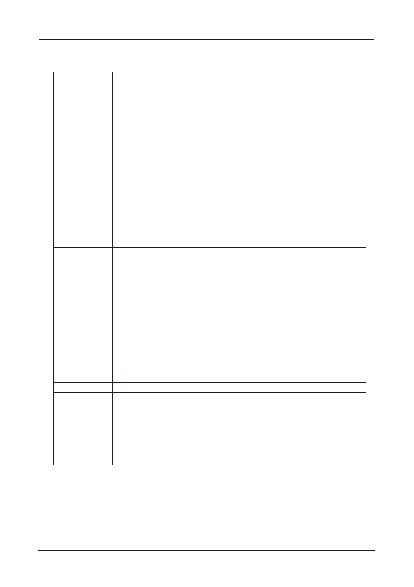
1.2 Specications
-Supports AMD® Socket AM2+/ AM2 processors:
CPU
Main Chipset
Main Memory
BIOS
Integrated Ports
Sound
Onboard LAN - Onboard 10/100/1000Mbps compatible LAN (Optional)
Expansion Slots
Form Factor - Mirco ATX
Remark
-AMD Phenom™ / Athlon™ 64 FX / Athlon™ 64 X2 Dual Core/ Athlon™
64 / Sempron™
-Hyper Transport Bus 5200/2000 MT/s (HT 3.0/1.0)
-Note: 125W TDP processors are not supported by this board
- AMD® 780G + SB700
- Built in Radeon™ HD 3200 Graphics, DirectX® 10 Ready
- Supports 2 x 1.8V DDR2 DIMM sockets supporting up to 4 GB of
system memory
- Supports Dual channel memory architecture
- Onboard side-port DDR2 memory
- Supports for DDR2 1066/800/667 MHz memory modules
- Supports ECC Memory(CPU dependent)
- AMI BIOS,supports Plug&Play
- Supports BIOS ROM Write Protect
- Supports Advanced Power Management ACPI,STR
- Supports 1x SYS FAN, 1x CPU FAN
- CPU temperature, Fan speed, System Voltage monitoring
- 1 x PS/2 Keyboard port
- 1 x DVI port
- 1 x Debug LED (Optional)
- 1 x HDMI port
- 1 x VGA port
- 1 x RJ45 port
- 8 x USB 2.0 ports, USB 1.1 is compliant
- 4 x SATA ports , Maximum Speed to 3GB/s,support for SATA
RAID 0, RAID 1 and RAID 10
- 1 x IDE connector, 2 x IDE devices could be connected,
Supports ATA 133/100/66/33
- 1 x Floppy Drive, supports 360K/720K/1.2M/1.44M/2.88M oppy disk
- Onboard 6-channel/8-channel HD Audio Codec (Optional)
- Front Panel Jumper, provides stereo MIC port on front panel
- 1 x PCI Express x16 slot (PCI Express 2.0)
- 2 x PCI slots
- Support PCI Bus interface v2.2 compliant
-1066 MHz memory support is dependent on the CPU being used
-ECC memory support is dependent on the CPU being used
- 4 -

AMD RS780 Series User's Manual
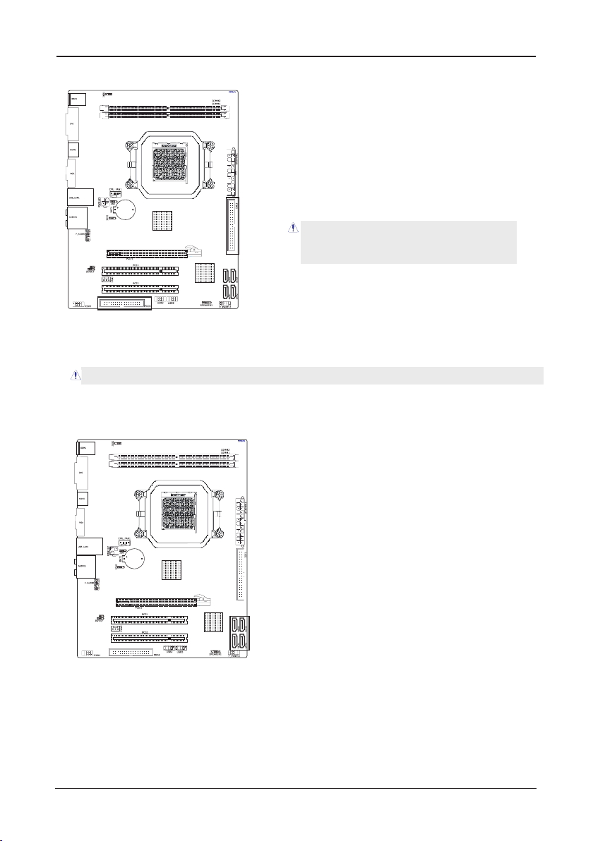
1.3 Mainboard Layout
(This picture is only for reference)
- 5 -
AMD RS780 Series User's Manual
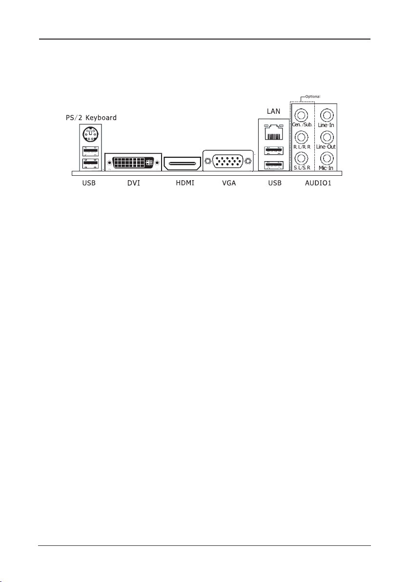
1.4 Connecting Rear Panel I/O Devices
The rear I/O part of these mainboard provides the following I/O ports:
(This picture is only for reference)
• PS/2 Keyboard: Connects to PS/2 keyboard.
• DVI: Connects to monitor input.
• HDMI:Connects to multimedia devices of HDMI protocol.
• VGA: Connects to monitor input.
• LAN: Connects to Local Area Network.
• USB: Connects to USB devices such as scanner, digital speakers, monitor, mouse, keyboard,
hub, digital camera, joystick etc.
• AUDIO1:
Cen./Sub. (Center / Subwoofer): Connects to the center and subwoofer channel in the 7.1
channel audio system. (Optional)
R.L./R.R. (Rear Left / Rear Right): Connects to the rear left and rear right channel in the 7.1
channel audio system. (Optional)
S.L./S.R. (Surround Left / Surround Right): Connects to the surround left and surround right
channel in the 7.1 channel audio system. (Optional)
Line-In: Connects to the line out from external audio sources.
Line-Out: Connects to the front left and front right channel in the 7.1-channel or regular
2-channel audio system.
Mic-In: Connects to the plug from external microphone.
- 6 -
AMD RS780 Series User's Manual
Chapter 2 Hardware Setup
2.1 Choosing a Computer Chassis
The mainboard and its component layouts illustrated in this chapter were
based mainly on model “
• Choose a chassis big enough to install this mainboard.
• As some features for this mainboard are implemented by cabling connectors on the
mainboard to indicators and switches or buttons on the chassis, make sure your chassis
supports all the features required.
• If there is possibility of adopting some more hard drives, make sure your chassis has
sufcient power and space for them.
• Most chassis have alternatives for I/O shield located at the rear panel. Make sure the I/O
shield of the chassis matches the I/O port conguration of this mainboard. You can nd
an I/O shield specically designed for this mainboard in its package.
For JRS780C01_DV1.11 PCB
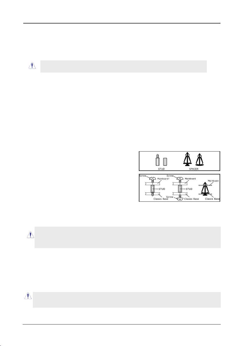
2.2 Installing Mainboard
Most computer chassis have a base with many mounting holes to allow the mainboard to
be securely attached, and at the same time, prevent the system from short circuits. There
are two ways to attach the mainboard to the
chassis base: (1) with studs, or (2) with spacers.
Basically, the best way to attach the board is with
studs. Only if you are unable to do this should you
attach the board with spacers. Line up the holes on
the board with the mounting holes on the chassis.
If the holes line up and there are screw holes, you
can attach the board with studs. If the holes line
up and there are only slots, you can only attach with
spacers. Take the tip of the spacers and insert them
into the slots. After doing this to all the slots, you can slide the board into position aligned
with slots. After the board has been positioned, check to make sure everything is OK before
putting the chassis back on.
”, unless speci cally stated.
Always power off the computer and unplug the AC power cord before adding or removing
any peripheral or component. Failing to do so may cause severe damage to your
mainboard and/or peripherals. Plug in the AC power cord only after you have carefully
checked everything.
To install this mainboard:
1. Locate all the screw holes on the mainboard and the chassis base.
2. Place all the studs or spacers needed on the chassis base and have them tightened.
3. Face the mainboard’s I/O ports toward the chassis’s rear panel.
4. Line up all the mainboard’s screw holes with those studs or spacers on the chassis.
5. Install the mainboard with screws and have them tightened.
To prevent shorting the PCB circuit, please REMOVE the metal studs or spacers if they are
already fastened on the chassis base and are without mounting-holes on the mainboard to
align with.
- 7 -
AMD RS780 Series User's Manual
2.3 Installation of the CPU and CPU Cooler
Before installing the CPU, please comply with the following conditions:
1. Please make sure that the mainboard supports the CPU.
2. Please take note of the one indented corner of the CPU. If you install the CPU in the wrong
direction, the CPU will not insert properly. If this occurs, please change the insert direction
of the CPU.
3. Please add an even layer of heat sink paste between the CPU and CPU cooler.
4. Please make sure the CPU cooler is installed on the CPU prior to system use, otherwise
overheating and permanent damage of the CPU may occur.
5. Please set the CPU host frequency in accordance with the processor specications. It is not
recommended that the system bus frequency be set beyond hardware specications since
it does not meet the required standards for the peripherals. If you wish to set the frequen-
cy beyond the proper specications, please do so according to your hardware
specications including the CPU, graphics card, memory, hard drive, etc.
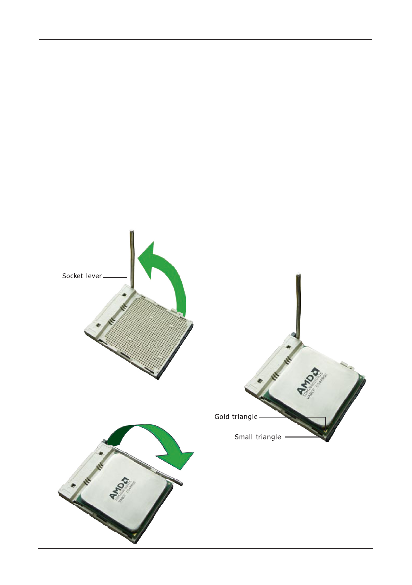
2.3.1 Installation of the CPU
1. Unlock the socket by pressing the
lever sideways, then lift it up to a 90o.
2. Position the CPU above the socket such
that the CPU corner with the gold
triangle matches the socket corner with
a small triangle.
3. Carefully insert the CPU into the socket
until it ts place.
Figure 1
4. When the CPU is in place, push down
the socket lever to secure the CPU.
The lever clicks on the side tab to
indicate that it is locked.
Figure 3
Figure 2
- 8 -

AMD RS780 Series User's Manual
Eje ctor Tab
Not ch K ey
Mou nting No tch
Rib
2.3.2 Installation of the CPU Cooler
For proper installation, please kindly refer to the instruction manuals of your CPU Cooler.
2.4 Installation of Memory Modules
This mainboard provides two 240-pin DDRII (Double Data Rate) DIMM slots, and supports
Dual Channel Memory Technology. For dual channel conguration, you always need to install
two identical (the same brand, speed, size and chip-type) memory modules in the DDRII
DIMM slots to activate Dual Channel Memory Technology. Otherwise, it will operate at single
channel mode.
Static electricity can damage the electronic components of the computer or optional
boards. Before starting these procedures, ensure that you are discharged of static
electricity by touching a grounded metal object briey.
To install system memory:
1. Power off the computer and unplug the
AC power cord before installing or
removing memory modules.
2. Locate the DIMM slot on the board.
3. Hold two edges of the DIMM module
carefully, keep away from touching its
connectors.
4. Align the notch key on the module with
the rib on the slot.
5. Firmly press the module into the slots until the ejector tabs at both sides of the slot
automatically snap into the mounting notch. Do not force the DIMM module in with extra
force as the DIMM module only ts in one direction.
6. To remove the DIMM modules, push the two ejector tabs on the slot outward
simultaneously, and then pull out the DIMM module.
- 9 -
AMD RS780 Series User's Manual
2.5 Connecting Peripheral Devices
2.5.1 Floppy and IDE Disk Drive Connectors
Each of the IDE port connects up to two IDE
drives at Ultra ATA 133/100/66/33 mode by
one 40-pin, 80-conductor,and 3-connector Ultra
ATA/66 ribbon cables.
Connect the single end (blue connector) at the
longer length of ribbon cable to the IDE port of
this board, the other two ends (gray and black
connector) at the shorter length of the ribbon
cable to the connectors of your hard drives.
Make sure to congure the “Master” and “Slave” relation
before connecting two drives by one single ribbon cable.
The red line on the ribbon cable must be aligned with
pin-1 on both the IDE port and the hard-drive connector.
The FDD connector connects up to two oppy drives with a 34-wire, 2-connector oppy
cable.Connect the single end at the longer length of ribbon cable to the FDD on the board,
the two connectors on the other end to the oppy disk drives connector. Generally you need
only one oppy disk drive in your system.
The red line on the ribbon cable must be aligned with pin-1 on both the FDD port and the oppy connector.
2.5.2 Serial ATA Connectors
Each SATA connector serves as one single channel to connect one SATA device by SATA
cable.
2.5.3 PCI and PCI Express slots
Install PCI Express X16 graphics card into slot “PCIE1”.
Install PCI card into slots “PCI1” or “PCI2” .
- 10 -
 Loading...