


 Loading...
Agilent X-Series
Signal Analyzer
This manual provides documentation for the following X-Series Analyzers:
PXA Signal Analyzer N9030A
MXA Signal Analyzer N9020A
EXA Signal Analyzer N9010A
N9061A
Remote Language
Compatibility Guide

Notices
© Agilent Technologies, Inc. 2008, 2009
No part of this manual may be reproduced in any form or by any means (including electronic storage and retrieval or translation into a foreign language) without prior agreement and written consent from Agilent Technologies, Inc. as governed by United States and international copyright laws.
Trademark
Acknowledgements
Microsoft→ is a U.S. registered trademark of Microsoft Corporation.
Windows→ and MS Windows→ are U.S. registered trademarks of Microsoft Corporation.
Adobe Reader→ is a U.S. registered trademark of Adobe System Incorporated.
Java™ is a U.S. trademark of Sun Microsystems, Inc.
MATLAB→ is a U.S. registered trademark of Math Works, Inc.
Norton Ghost™ is a U.S. trademark of Symantec Corporation.
Manual Part Number
N9020-90119
Supersedes: August 2009
Print Date
October 2009
Printed in USA
Agilent Technologies, Inc.
1400 Fountaingrove Parkway
Santa Rosa, CA 95403
Warranty
The material contained in this document is provided “as is,” and is subject to being changed, without notice, in future editions. Further, to the maximum extent permitted by applicable law, Agilent disclaims all warranties, either express or implied, with regard to this manual and any information contained herein, including but not limited to the implied warranties of merchantability and fitness for a particular purpose. Agilent shall not be liable for errors or for incidental or consequential damages in connection with the furnishing, use, or performance of this document or of any information contained herein. Should Agilent and the user have a separate written agreement with warranty terms covering the material in this document that conflict with these terms, the warranty terms in the separate agreement shall control.
Technology Licenses
The hardware and/or software described in this document are furnished under a license and may be used or copied only in accordance with the terms of such license.
Restricted Rights Legend
If software is for use in the performance of a U.S. Government prime contract or subcontract, Software is delivered and
licensed as “Commercial computer software” as defined in DFAR 252.227-7014 (June 1995), or as a “commercial item” as defined in FAR 2.101(a) or as “Restricted computer software” as defined in FAR 52.227-19 (June 1987) or any equivalent agency regulation or contract clause. Use, duplication or disclosure of Software is subject to Agilent Technologies’ standard commercial license terms, and nonDOD Departments and Agencies of the U.S. Government will receive no greater than Restricted Rights as defined in FAR 52.227-19(c)(1-2) (June 1987). U.S. Government users will receive no greater than Limited Rights as defined in FAR 52.22714 (June 1987) or DFAR 252.227-7015 (b)(2) (November 1995), as applicable in any technical data.
Safety Notices
CAUTION
A CAUTION notice denotes a hazard. It calls attention to an operating procedure, practice, or the like that, if not correctly performed or adhered to, could result in damage to the product or loss of important data. Do not proceed beyond a CAUTION notice until the indicated conditions are fully understood and met.
WARNING
A WARNING notice denotes a hazard. It calls attention to an operating procedure, practice, or the like that, if not correctly performed or adhered to, could result in personal injury or death. Do not proceed beyond a WARNING notice until the indicated conditions are fully understood and met.
2

Warranty
This Agilent technologies instrument product is warranted against defects in material and workmanship for a period of one year from the date of shipment. During the warranty period, Agilent Technologies will, at its option, either repair or replace products that prove to be defective.
For warranty service or repair, this product must be returned to a service facility designated by Agilent Technologies. Buyer shall prepay shipping charges to Agilent Technologies and Agilent Technologies shall pay shipping charges to return the product to Buyer. However, Buyer shall pay all shipping charges, duties, and taxes for products returned to Agilent Technologies from another country.
Where to Find the Latest Information
Documentation is updated periodically. For the latest information about this analyzer, including firmware upgrades, application information, and product information, see the following URLs:
http://www.agilent.com/find/pxa
http://www.agilent.com/find/mxa
http://www.agilent.com/find/exa
To receive the latest updates by email, subscribe to Agilent Email Updates:
http://www.agilent.com/find/emailupdates
Information on preventing analyzer damage can be found at:
http://www.agilent.com/find/tips
3

4

Contents
1.Getting Started
N9061A Application Description . . . . . . . . . . . . . . . . . . . . . . . . . . . . . . . . . . . . . . . . . . . . . . . . . . . . . . . . 18 Documentation for the N9061A application . . . . . . . . . . . . . . . . . . . . . . . . . . . . . . . . . . . . . . . . . . . . . . . . 19 N9061A General Rules and Limitations . . . . . . . . . . . . . . . . . . . . . . . . . . . . . . . . . . . . . . . . . . . . . . . . . . . 20 Hardware and Firmware Requirements for N9061A . . . . . . . . . . . . . . . . . . . . . . . . . . . . . . . . . . . . . . . . . . 23 Installing the N9061A application . . . . . . . . . . . . . . . . . . . . . . . . . . . . . . . . . . . . . . . . . . . . . . . . . . . . . . . . 25 Setting up N9061A on the X-Series Analyzer . . . . . . . . . . . . . . . . . . . . . . . . . . . . . . . . . . . . . . . . . . . . . . . 27 Running Software that Requires SCPI Commands . . . . . . . . . . . . . . . . . . . . . . . . . . . . . . . . . . . . . . . . . . . 38 Service and Calibration . . . . . . . . . . . . . . . . . . . . . . . . . . . . . . . . . . . . . . . . . . . . . . . . . . . . . . . . . . . . . . . . 40
2.Legacy Analyzer Command List
Table of All Legacy Analyzer Commands . . . . . . . . . . . . . . . . . . . . . . . . . . . . . . . . . . . . . . . . . . . . . . . . . . 42
3.Hints and Tips
Hints and Tips . . . . . . . . . . . . . . . . . . . . . . . . . . . . . . . . . . . . . . . . . . . . . . . . . . . . . . . . . . . . . . . . . . . . . . . 72
4.Programming Commands
Command Syntax . . . . . . . . . . . . . . . . . . . . . . . . . . . . . . . . . . . . . . . . . . . . . . . . . . . . . . . . . . . . . . . . . . . . . 76 Programming Command Descriptions . . . . . . . . . . . . . . . . . . . . . . . . . . . . . . . . . . . . . . . . . . . . . . . . . . . . . 78 A1 [one]
Clear Write for Trace A . . . . . . . . . . . . . . . . . . . . . . . . . . . . . . . . . . . . . . . . . . . . . . . . . . . . . . . . . . . . . . . . 79 A2 [two]
Maximum Hold for Trace A . . . . . . . . . . . . . . . . . . . . . . . . . . . . . . . . . . . . . . . . . . . . . . . . . . . . . . . . . . . . 80 A3 [three]
View Mode for Trace A . . . . . . . . . . . . . . . . . . . . . . . . . . . . . . . . . . . . . . . . . . . . . . . . . . . . . . . . . . . . . . . . 81 A4 [four]
Blank Trace A . . . . . . . . . . . . . . . . . . . . . . . . . . . . . . . . . . . . . . . . . . . . . . . . . . . . . . . . . . . . . . . . . . . . . . . 82 ACPALPHA
Adjacent Channel Power Alpha Weighting . . . . . . . . . . . . . . . . . . . . . . . . . . . . . . . . . . . . . . . . . . . . . . . . . 83 ACPALTCH
Adjacent Channel Power Alternate Channels . . . . . . . . . . . . . . . . . . . . . . . . . . . . . . . . . . . . . . . . . . . . . . . 84 ACPBRPER
Adjacent Channel Power Burst Period . . . . . . . . . . . . . . . . . . . . . . . . . . . . . . . . . . . . . . . . . . . . . . . . . . . . 85 ACPBRWID
Adjacent Channel Power Burst Width . . . . . . . . . . . . . . . . . . . . . . . . . . . . . . . . . . . . . . . . . . . . . . . . . . . . . 86 ACPBW
Adjacent Channel Power Bandwidth . . . . . . . . . . . . . . . . . . . . . . . . . . . . . . . . . . . . . . . . . . . . . . . . . . . . . . 87 ACPCOMPUTE
Adjacent Channel Power Compute . . . . . . . . . . . . . . . . . . . . . . . . . . . . . . . . . . . . . . . . . . . . . . . . . . . . . . . 88 ACPFRQWT
Adjacent Channel Power Frequency Weighting . . . . . . . . . . . . . . . . . . . . . . . . . . . . . . . . . . . . . . . . . . . . . 89 ACPLOWER
Lower Adjacent Channel Power . . . . . . . . . . . . . . . . . . . . . . . . . . . . . . . . . . . . . . . . . . . . . . . . . . . . . . . . . 90 ACPMAX
Maximum Adjacent Channel Power . . . . . . . . . . . . . . . . . . . . . . . . . . . . . . . . . . . . . . . . . . . . . . . . . . . . . . 91 ACPMEAS
Measure Adjacent Channel Power . . . . . . . . . . . . . . . . . . . . . . . . . . . . . . . . . . . . . . . . . . . . . . . . . . . . . . . . 92 ACPMSTATE
5

Contents
Adjacent Channel Power Measurement State . . . . . . . . . . . . . . . . . . . . . . . . . . . . . . . . . . . . . . . . . . . . . . |
. 93 |
ACPPWRTX |
|
Adjacent Channel Power Total Power Transmitted . . . . . . . . . . . . . . . . . . . . . . . . . . . . . . . . . . . . . . . . . . |
. 94 |
ACPRSLTS |
|
Adjacent Channel Power Measurement Results . . . . . . . . . . . . . . . . . . . . . . . . . . . . . . . . . . . . . . . . . . . . . |
95 |
ACPSP |
|
Adjacent Channel Power Channel Spacing . . . . . . . . . . . . . . . . . . . . . . . . . . . . . . . . . . . . . . . . . . . . . . . . . |
96 |
ACPT |
|
Adjacent Channel Power T Weighting . . . . . . . . . . . . . . . . . . . . . . . . . . . . . . . . . . . . . . . . . . . . . . . . . . . . |
97 |
ACPUPPER |
|
Upper Adjacent Channel Power . . . . . . . . . . . . . . . . . . . . . . . . . . . . . . . . . . . . . . . . . . . . . . . . . . . . . . . . . |
98 |
ADJALL |
|
LO and IF Adjustments . . . . . . . . . . . . . . . . . . . . . . . . . . . . . . . . . . . . . . . . . . . . . . . . . . . . . . . . . . . . . . . . |
99 |
AMB |
|
A minus B into A . . . . . . . . . . . . . . . . . . . . . . . . . . . . . . . . . . . . . . . . . . . . . . . . . . . . . . . . . . . . . . . . . . . . |
100 |
AMBPL |
|
(A minus B) plus Display Line into A . . . . . . . . . . . . . . . . . . . . . . . . . . . . . . . . . . . . . . . . . . . . . . . . . . . . |
101 |
ANNOT |
|
Annotation . . . . . . . . . . . . . . . . . . . . . . . . . . . . . . . . . . . . . . . . . . . . . . . . . . . . . . . . . . . . . . . . . . . . . . . . . |
102 |
APB |
|
Trace A Plus Trace B to A . . . . . . . . . . . . . . . . . . . . . . . . . . . . . . . . . . . . . . . . . . . . . . . . . . . . . . . . . . . . . |
103 |
AT |
|
Input Attenuation . . . . . . . . . . . . . . . . . . . . . . . . . . . . . . . . . . . . . . . . . . . . . . . . . . . . . . . . . . . . . . . . . . . . |
104 |
AUNITS |
|
Absolute Amplitude Units . . . . . . . . . . . . . . . . . . . . . . . . . . . . . . . . . . . . . . . . . . . . . . . . . . . . . . . . . . . . . |
106 |
AUTOCPL |
|
Auto Coupled . . . . . . . . . . . . . . . . . . . . . . . . . . . . . . . . . . . . . . . . . . . . . . . . . . . . . . . . . . . . . . . . . . . . . . . |
108 |
AXB |
|
Exchange Trace A and Trace B . . . . . . . . . . . . . . . . . . . . . . . . . . . . . . . . . . . . . . . . . . . . . . . . . . . . . . . . . |
109 |
B1 [one] |
|
Clear Write for Trace B . . . . . . . . . . . . . . . . . . . . . . . . . . . . . . . . . . . . . . . . . . . . . . . . . . . . . . . . . . . . . . . |
110 |
B2 [two] |
|
Maximum Hold for Trace B . . . . . . . . . . . . . . . . . . . . . . . . . . . . . . . . . . . . . . . . . . . . . . . . . . . . . . . . . . . |
111 |
B3 [three] |
|
View Mode for Trace B . . . . . . . . . . . . . . . . . . . . . . . . . . . . . . . . . . . . . . . . . . . . . . . . . . . . . . . . . . . . . . . |
112 |
B4 [four] |
|
Blank Trace B . . . . . . . . . . . . . . . . . . . . . . . . . . . . . . . . . . . . . . . . . . . . . . . . . . . . . . . . . . . . . . . . . . . . . . |
113 |
BL |
|
Trace B minus Display Line to Trace B . . . . . . . . . . . . . . . . . . . . . . . . . . . . . . . . . . . . . . . . . . . . . . . . . . |
114 |
BLANK |
|
Blank Trace . . . . . . . . . . . . . . . . . . . . . . . . . . . . . . . . . . . . . . . . . . . . . . . . . . . . . . . . . . . . . . . . . . . . . . . . |
115 |
BML |
|
Trace B Minus Display Line . . . . . . . . . . . . . . . . . . . . . . . . . . . . . . . . . . . . . . . . . . . . . . . . . . . . . . . . . . . |
116 |
BTC |
|
Transfer Trace B to Trace C . . . . . . . . . . . . . . . . . . . . . . . . . . . . . . . . . . . . . . . . . . . . . . . . . . . . . . . . . . . |
117 |
BXC |
|
Exchange Trace B and Trace C . . . . . . . . . . . . . . . . . . . . . . . . . . . . . . . . . . . . . . . . . . . . . . . . . . . . . . . . . |
118 |
C1 [one] |
|
Set A Minus B Mode Off . . . . . . . . . . . . . . . . . . . . . . . . . . . . . . . . . . . . . . . . . . . . . . . . . . . . . . . . . . . . . |
119 |
6

Contents
C2 [two]
A Minus B Into A . . . . . . . . . . . . . . . . . . . . . . . . . . . . . . . . . . . . . . . . . . . . . . . . . . . . . . . . . . . . . . . . . . . 120 CA
Couple Attenuation . . . . . . . . . . . . . . . . . . . . . . . . . . . . . . . . . . . . . . . . . . . . . . . . . . . . . . . . . . . . . . . . . . 121 CARROFF
Carrier Off Power . . . . . . . . . . . . . . . . . . . . . . . . . . . . . . . . . . . . . . . . . . . . . . . . . . . . . . . . . . . . . . . . . . . 122 CARRON
Carrier On Power . . . . . . . . . . . . . . . . . . . . . . . . . . . . . . . . . . . . . . . . . . . . . . . . . . . . . . . . . . . . . . . . . . . . 123 CF
Center Frequency . . . . . . . . . . . . . . . . . . . . . . . . . . . . . . . . . . . . . . . . . . . . . . . . . . . . . . . . . . . . . . . . . . . . 124 CHANNEL
Channel Selection . . . . . . . . . . . . . . . . . . . . . . . . . . . . . . . . . . . . . . . . . . . . . . . . . . . . . . . . . . . . . . . . . . . 126 CHANPWR
Channel Power . . . . . . . . . . . . . . . . . . . . . . . . . . . . . . . . . . . . . . . . . . . . . . . . . . . . . . . . . . . . . . . . . . . . . . 127 CHPWRBW
Channel Power Bandwidth . . . . . . . . . . . . . . . . . . . . . . . . . . . . . . . . . . . . . . . . . . . . . . . . . . . . . . . . . . . . 128 CLRAVG
Clear Average . . . . . . . . . . . . . . . . . . . . . . . . . . . . . . . . . . . . . . . . . . . . . . . . . . . . . . . . . . . . . . . . . . . . . . . 129 CLRW
Clear Write . . . . . . . . . . . . . . . . . . . . . . . . . . . . . . . . . . . . . . . . . . . . . . . . . . . . . . . . . . . . . . . . . . . . . . . . . 130 CONTS
Continuous Sweep . . . . . . . . . . . . . . . . . . . . . . . . . . . . . . . . . . . . . . . . . . . . . . . . . . . . . . . . . . . . . . . . . . . 132 COUPLE
Input Coupling . . . . . . . . . . . . . . . . . . . . . . . . . . . . . . . . . . . . . . . . . . . . . . . . . . . . . . . . . . . . . . . . . . . . . . 133 CR
Couple Resolution Bandwidth . . . . . . . . . . . . . . . . . . . . . . . . . . . . . . . . . . . . . . . . . . . . . . . . . . . . . . . . . . 134 CS
Couple Frequency Step Size . . . . . . . . . . . . . . . . . . . . . . . . . . . . . . . . . . . . . . . . . . . . . . . . . . . . . . . . . . . 135 CT
Couple Sweep Time . . . . . . . . . . . . . . . . . . . . . . . . . . . . . . . . . . . . . . . . . . . . . . . . . . . . . . . . . . . . . . . . . . 136 CV
Couple Video Bandwidth . . . . . . . . . . . . . . . . . . . . . . . . . . . . . . . . . . . . . . . . . . . . . . . . . . . . . . . . . . . . . . 137 DA
Display Address . . . . . . . . . . . . . . . . . . . . . . . . . . . . . . . . . . . . . . . . . . . . . . . . . . . . . . . . . . . . . . . . . . . . . 138 DELMKBW
Occupied Power Bandwidth Within Delta Marker . . . . . . . . . . . . . . . . . . . . . . . . . . . . . . . . . . . . . . . . . . 139 DET
Detection Mode . . . . . . . . . . . . . . . . . . . . . . . . . . . . . . . . . . . . . . . . . . . . . . . . . . . . . . . . . . . . . . . . . . . . . 140 DL
Display Line . . . . . . . . . . . . . . . . . . . . . . . . . . . . . . . . . . . . . . . . . . . . . . . . . . . . . . . . . . . . . . . . . . . . . . . . 141 DLE
Display Line Enable . . . . . . . . . . . . . . . . . . . . . . . . . . . . . . . . . . . . . . . . . . . . . . . . . . . . . . . . . . . . . . . . . . 143 DLYSWP
Delay Sweep . . . . . . . . . . . . . . . . . . . . . . . . . . . . . . . . . . . . . . . . . . . . . . . . . . . . . . . . . . . . . . . . . . . . . . . 144 DONE
Done . . . . . . . . . . . . . . . . . . . . . . . . . . . . . . . . . . . . . . . . . . . . . . . . . . . . . . . . . . . . . . . . . . . . . . . . . . . . . . 145 DR
Display Read . . . . . . . . . . . . . . . . . . . . . . . . . . . . . . . . . . . . . . . . . . . . . . . . . . . . . . . . . . . . . . . . . . . . . . . 146 E1[one]
7

Contents
Peak Marker . . . . . . . . . . . . . . . . . . . . . . . . . . . . . . . . . . . . . . . . . . . . . . . . . . . . . . . . . . . . . . . . . . . . . . . . 147 E2 [two]
Marker to Center Frequency . . . . . . . . . . . . . . . . . . . . . . . . . . . . . . . . . . . . . . . . . . . . . . . . . . . . . . . . . . . 148 E3 [three]
Delta Marker Step Size . . . . . . . . . . . . . . . . . . . . . . . . . . . . . . . . . . . . . . . . . . . . . . . . . . . . . . . . . . . . . . . 149 E4 [four]
Marker to Reference Level . . . . . . . . . . . . . . . . . . . . . . . . . . . . . . . . . . . . . . . . . . . . . . . . . . . . . . . . . . . . 150 EDITDONE
Edit Done . . . . . . . . . . . . . . . . . . . . . . . . . . . . . . . . . . . . . . . . . . . . . . . . . . . . . . . . . . . . . . . . . . . . . . . . . . 151 ERR
Error . . . . . . . . . . . . . . . . . . . . . . . . . . . . . . . . . . . . . . . . . . . . . . . . . . . . . . . . . . . . . . . . . . . . . . . . . . . . . . 152 ET
Elapsed Time . . . . . . . . . . . . . . . . . . . . . . . . . . . . . . . . . . . . . . . . . . . . . . . . . . . . . . . . . . . . . . . . . . . . . . . 154 EX
Exchange Trace A and Trace B . . . . . . . . . . . . . . . . . . . . . . . . . . . . . . . . . . . . . . . . . . . . . . . . . . . . . . . . . 155 FA
Start Frequency . . . . . . . . . . . . . . . . . . . . . . . . . . . . . . . . . . . . . . . . . . . . . . . . . . . . . . . . . . . . . . . . . . . . . 156 FB
Stop Frequency . . . . . . . . . . . . . . . . . . . . . . . . . . . . . . . . . . . . . . . . . . . . . . . . . . . . . . . . . . . . . . . . . . . . . 157 FDSP
Frequency Display Off . . . . . . . . . . . . . . . . . . . . . . . . . . . . . . . . . . . . . . . . . . . . . . . . . . . . . . . . . . . . . . . 158 FOFFSET
Frequency Offset . . . . . . . . . . . . . . . . . . . . . . . . . . . . . . . . . . . . . . . . . . . . . . . . . . . . . . . . . . . . . . . . . . . . 159 FPKA
Fast Preselector Peak . . . . . . . . . . . . . . . . . . . . . . . . . . . . . . . . . . . . . . . . . . . . . . . . . . . . . . . . . . . . . . . . . 161 FREF
Frequency Reference . . . . . . . . . . . . . . . . . . . . . . . . . . . . . . . . . . . . . . . . . . . . . . . . . . . . . . . . . . . . . . . . . 162 FS
Full Span . . . . . . . . . . . . . . . . . . . . . . . . . . . . . . . . . . . . . . . . . . . . . . . . . . . . . . . . . . . . . . . . . . . . . . . . . . 163 GATE
Gate . . . . . . . . . . . . . . . . . . . . . . . . . . . . . . . . . . . . . . . . . . . . . . . . . . . . . . . . . . . . . . . . . . . . . . . . . . . . . . 166 GATECTL
Gate Control . . . . . . . . . . . . . . . . . . . . . . . . . . . . . . . . . . . . . . . . . . . . . . . . . . . . . . . . . . . . . . . . . . . . . . . 167 GD
Gate Delay . . . . . . . . . . . . . . . . . . . . . . . . . . . . . . . . . . . . . . . . . . . . . . . . . . . . . . . . . . . . . . . . . . . . . . . . . 168 GL
Gate Length . . . . . . . . . . . . . . . . . . . . . . . . . . . . . . . . . . . . . . . . . . . . . . . . . . . . . . . . . . . . . . . . . . . . . . . . 169 GP
Gate Polarity . . . . . . . . . . . . . . . . . . . . . . . . . . . . . . . . . . . . . . . . . . . . . . . . . . . . . . . . . . . . . . . . . . . . . . . 170 GRAT
Graticule . . . . . . . . . . . . . . . . . . . . . . . . . . . . . . . . . . . . . . . . . . . . . . . . . . . . . . . . . . . . . . . . . . . . . . . . . . 171 HD
Hold Data Entry . . . . . . . . . . . . . . . . . . . . . . . . . . . . . . . . . . . . . . . . . . . . . . . . . . . . . . . . . . . . . . . . . . . . . 172 I1 [one]
Set RF Coupling to DC . . . . . . . . . . . . . . . . . . . . . . . . . . . . . . . . . . . . . . . . . . . . . . . . . . . . . . . . . . . . . . . 173 I2 [two]
Set RF Coupling to AC . . . . . . . . . . . . . . . . . . . . . . . . . . . . . . . . . . . . . . . . . . . . . . . . . . . . . . . . . . . . . . . 175 ID
Identify . . . . . . . . . . . . . . . . . . . . . . . . . . . . . . . . . . . . . . . . . . . . . . . . . . . . . . . . . . . . . . . . . . . . . . . . . . . 177
8

Contents
IP
Instrument Preset . . . . . . . . . . . . . . . . . . . . . . . . . . . . . . . . . . . . . . . . . . . . . . . . . . . . . . . . . . . . . . . . . . . . 178 KS,
Mixer Level . . . . . . . . . . . . . . . . . . . . . . . . . . . . . . . . . . . . . . . . . . . . . . . . . . . . . . . . . . . . . . . . . . . . . . . . 179 KS=
8566A/B: Automatic Preselector Tracking
8568A/B: Marker Counter Resolution . . . . . . . . . . . . . . . . . . . . . . . . . . . . . . . . . . . . . . . . . . . . . . . . . . . . 180 KS(
Lock Registers . . . . . . . . . . . . . . . . . . . . . . . . . . . . . . . . . . . . . . . . . . . . . . . . . . . . . . . . . . . . . . . . . . . . . . 181 KS)
Unlock Registers . . . . . . . . . . . . . . . . . . . . . . . . . . . . . . . . . . . . . . . . . . . . . . . . . . . . . . . . . . . . . . . . . . . . 182 KSA
Amplitude in dBm . . . . . . . . . . . . . . . . . . . . . . . . . . . . . . . . . . . . . . . . . . . . . . . . . . . . . . . . . . . . . . . . . . . 183 KSa
Normal Detection . . . . . . . . . . . . . . . . . . . . . . . . . . . . . . . . . . . . . . . . . . . . . . . . . . . . . . . . . . . . . . . . . . . . 184 KSB
Amplitude in dBmV . . . . . . . . . . . . . . . . . . . . . . . . . . . . . . . . . . . . . . . . . . . . . . . . . . . . . . . . . . . . . . . . . . 185 KSb
Positive Peak Detection . . . . . . . . . . . . . . . . . . . . . . . . . . . . . . . . . . . . . . . . . . . . . . . . . . . . . . . . . . . . . . . 186 KSC
Amplitude in dBuV . . . . . . . . . . . . . . . . . . . . . . . . . . . . . . . . . . . . . . . . . . . . . . . . . . . . . . . . . . . . . . . . . . 187 KSc
A Plus B to A . . . . . . . . . . . . . . . . . . . . . . . . . . . . . . . . . . . . . . . . . . . . . . . . . . . . . . . . . . . . . . . . . . . . . . . 188 KSD
Amplitude in Volts . . . . . . . . . . . . . . . . . . . . . . . . . . . . . . . . . . . . . . . . . . . . . . . . . . . . . . . . . . . . . . . . . . . 189 KSd
Negative Peak Detection . . . . . . . . . . . . . . . . . . . . . . . . . . . . . . . . . . . . . . . . . . . . . . . . . . . . . . . . . . . . . . 190 KSE
Title Mode . . . . . . . . . . . . . . . . . . . . . . . . . . . . . . . . . . . . . . . . . . . . . . . . . . . . . . . . . . . . . . . . . . . . . . . . . 191 KSe
Sample Detection . . . . . . . . . . . . . . . . . . . . . . . . . . . . . . . . . . . . . . . . . . . . . . . . . . . . . . . . . . . . . . . . . . . . 192 KSG
Video Averaging On . . . . . . . . . . . . . . . . . . . . . . . . . . . . . . . . . . . . . . . . . . . . . . . . . . . . . . . . . . . . . . . . . 193 KSg
Display Off . . . . . . . . . . . . . . . . . . . . . . . . . . . . . . . . . . . . . . . . . . . . . . . . . . . . . . . . . . . . . . . . . . . . . . . . . 194 KSH
Video Averaging Off . . . . . . . . . . . . . . . . . . . . . . . . . . . . . . . . . . . . . . . . . . . . . . . . . . . . . . . . . . . . . . . . . 195 KSh
Display On . . . . . . . . . . . . . . . . . . . . . . . . . . . . . . . . . . . . . . . . . . . . . . . . . . . . . . . . . . . . . . . . . . . . . . . . . 196 KSi
Exchange Trace B and Trace C . . . . . . . . . . . . . . . . . . . . . . . . . . . . . . . . . . . . . . . . . . . . . . . . . . . . . . . . . 197 KSj
View Trace C . . . . . . . . . . . . . . . . . . . . . . . . . . . . . . . . . . . . . . . . . . . . . . . . . . . . . . . . . . . . . . . . . . . . . . . 198 KSK
Marker to Next Peak . . . . . . . . . . . . . . . . . . . . . . . . . . . . . . . . . . . . . . . . . . . . . . . . . . . . . . . . . . . . . . . . . 199 KSk
Blank Trace C . . . . . . . . . . . . . . . . . . . . . . . . . . . . . . . . . . . . . . . . . . . . . . . . . . . . . . . . . . . . . . . . . . . . . . 200 KSL
Marker Noise Off . . . . . . . . . . . . . . . . . . . . . . . . . . . . . . . . . . . . . . . . . . . . . . . . . . . . . . . . . . . . . . . . . . . . 201
9

Contents
KSl
Transfer Trace B to Trace C . . . . . . . . . . . . . . . . . . . . . . . . . . . . . . . . . . . . . . . . . . . . . . . . . . . . . . . . . . . 202 KSM
Marker Noise On . . . . . . . . . . . . . . . . . . . . . . . . . . . . . . . . . . . . . . . . . . . . . . . . . . . . . . . . . . . . . . . . . . . . 203 KSm
Graticule Off . . . . . . . . . . . . . . . . . . . . . . . . . . . . . . . . . . . . . . . . . . . . . . . . . . . . . . . . . . . . . . . . . . . . . . . 204 KSN
Marker Minimum . . . . . . . . . . . . . . . . . . . . . . . . . . . . . . . . . . . . . . . . . . . . . . . . . . . . . . . . . . . . . . . . . . . 205 KSn
Graticule On . . . . . . . . . . . . . . . . . . . . . . . . . . . . . . . . . . . . . . . . . . . . . . . . . . . . . . . . . . . . . . . . . . . . . . . 206 KSO
Marker Span . . . . . . . . . . . . . . . . . . . . . . . . . . . . . . . . . . . . . . . . . . . . . . . . . . . . . . . . . . . . . . . . . . . . . . . 207 KSo
Annotation Off . . . . . . . . . . . . . . . . . . . . . . . . . . . . . . . . . . . . . . . . . . . . . . . . . . . . . . . . . . . . . . . . . . . . . . 208 KSp
Annotation On . . . . . . . . . . . . . . . . . . . . . . . . . . . . . . . . . . . . . . . . . . . . . . . . . . . . . . . . . . . . . . . . . . . . . . 209 KST
Fast Preset . . . . . . . . . . . . . . . . . . . . . . . . . . . . . . . . . . . . . . . . . . . . . . . . . . . . . . . . . . . . . . . . . . . . . . . . . 210 KSV
Frequency Offset . . . . . . . . . . . . . . . . . . . . . . . . . . . . . . . . . . . . . . . . . . . . . . . . . . . . . . . . . . . . . . . . . . . . 211 KSx
External Trigger . . . . . . . . . . . . . . . . . . . . . . . . . . . . . . . . . . . . . . . . . . . . . . . . . . . . . . . . . . . . . . . . . . . . . 212 KSy
Video Trigger . . . . . . . . . . . . . . . . . . . . . . . . . . . . . . . . . . . . . . . . . . . . . . . . . . . . . . . . . . . . . . . . . . . . . . . 213 KSZ
Reference Level Offset . . . . . . . . . . . . . . . . . . . . . . . . . . . . . . . . . . . . . . . . . . . . . . . . . . . . . . . . . . . . . . . 214 L0 [zero]
Display Line Off . . . . . . . . . . . . . . . . . . . . . . . . . . . . . . . . . . . . . . . . . . . . . . . . . . . . . . . . . . . . . . . . . . . . 215 LF
Low Frequency Preset . . . . . . . . . . . . . . . . . . . . . . . . . . . . . . . . . . . . . . . . . . . . . . . . . . . . . . . . . . . . . . . . 216 LG
Logarithmic Scale . . . . . . . . . . . . . . . . . . . . . . . . . . . . . . . . . . . . . . . . . . . . . . . . . . . . . . . . . . . . . . . . . . . 217 LIMF
Limit Line Frequency Value . . . . . . . . . . . . . . . . . . . . . . . . . . . . . . . . . . . . . . . . . . . . . . . . . . . . . . . . . . . 219 LIMIFAIL
Limits Failed . . . . . . . . . . . . . . . . . . . . . . . . . . . . . . . . . . . . . . . . . . . . . . . . . . . . . . . . . . . . . . . . . . . . . . . 220 LIMIPURGE
Delete Current Limit Line . . . . . . . . . . . . . . . . . . . . . . . . . . . . . . . . . . . . . . . . . . . . . . . . . . . . . . . . . . . . . 221 LIMIREL
Relative Limit Lines . . . . . . . . . . . . . . . . . . . . . . . . . . . . . . . . . . . . . . . . . . . . . . . . . . . . . . . . . . . . . . . . . 222 LIML
Lower-Limit Amplitude . . . . . . . . . . . . . . . . . . . . . . . . . . . . . . . . . . . . . . . . . . . . . . . . . . . . . . . . . . . . . . 223 LIMTSL
Slope Limit Line . . . . . . . . . . . . . . . . . . . . . . . . . . . . . . . . . . . . . . . . . . . . . . . . . . . . . . . . . . . . . . . . . . . . 224 LIMU
Upper-Limit Amplitude . . . . . . . . . . . . . . . . . . . . . . . . . . . . . . . . . . . . . . . . . . . . . . . . . . . . . . . . . . . . . . . 225 LN
Linear Scale . . . . . . . . . . . . . . . . . . . . . . . . . . . . . . . . . . . . . . . . . . . . . . . . . . . . . . . . . . . . . . . . . . . . . . . . 226 M1 [one]
10
Contents
Marker Off . . . . . . . . . . . . . . . . . . . . . . . . . . . . . . . . . . . . . . . . . . . . . . . . . . . . . . . . . . . . . . . . . . . . . . . . . |
227 |
M2 [two] |
|
Marker Normal . . . . . . . . . . . . . . . . . . . . . . . . . . . . . . . . . . . . . . . . . . . . . . . . . . . . . . . . . . . . . . . . . . . . . |
228 |
M3 [three] |
|
Delta Marker . . . . . . . . . . . . . . . . . . . . . . . . . . . . . . . . . . . . . . . . . . . . . . . . . . . . . . . . . . . . . . . . . . . . . . . |
229 |
M4 [four] |
|
Marker Zoom . . . . . . . . . . . . . . . . . . . . . . . . . . . . . . . . . . . . . . . . . . . . . . . . . . . . . . . . . . . . . . . . . . . . . . . |
230 |
MA |
|
Marker Amplitude Output . . . . . . . . . . . . . . . . . . . . . . . . . . . . . . . . . . . . . . . . . . . . . . . . . . . . . . . . . . . . . |
231 |
MC0 [zero] |
|
Marker Frequency Counter Off . . . . . . . . . . . . . . . . . . . . . . . . . . . . . . . . . . . . . . . . . . . . . . . . . . . . . . . . . |
232 |
MC1 [one] |
|
Marker Frequency Counter On . . . . . . . . . . . . . . . . . . . . . . . . . . . . . . . . . . . . . . . . . . . . . . . . . . . . . . . . . |
233 |
MDS |
|
Measurement Data Size . . . . . . . . . . . . . . . . . . . . . . . . . . . . . . . . . . . . . . . . . . . . . . . . . . . . . . . . . . . . . . |
234 |
MEAN |
|
Trace Mean . . . . . . . . . . . . . . . . . . . . . . . . . . . . . . . . . . . . . . . . . . . . . . . . . . . . . . . . . . . . . . . . . . . . . . . . |
235 |
MEANPWR |
|
Mean Power measurement . . . . . . . . . . . . . . . . . . . . . . . . . . . . . . . . . . . . . . . . . . . . . . . . . . . . . . . . . . . . . |
236 |
MEAS |
|
Meas . . . . . . . . . . . . . . . . . . . . . . . . . . . . . . . . . . . . . . . . . . . . . . . . . . . . . . . . . . . . . . . . . . . . . . . . . . . . . . |
237 |
MF |
|
Marker Frequency Output . . . . . . . . . . . . . . . . . . . . . . . . . . . . . . . . . . . . . . . . . . . . . . . . . . . . . . . . . . . . . |
238 |
MINH |
|
Minimum Hold . . . . . . . . . . . . . . . . . . . . . . . . . . . . . . . . . . . . . . . . . . . . . . . . . . . . . . . . . . . . . . . . . . . . . |
239 |
MINPOS |
|
Minimum X Position . . . . . . . . . . . . . . . . . . . . . . . . . . . . . . . . . . . . . . . . . . . . . . . . . . . . . . . . . . . . . . . . . |
240 |
MKA |
|
Marker Amplitude . . . . . . . . . . . . . . . . . . . . . . . . . . . . . . . . . . . . . . . . . . . . . . . . . . . . . . . . . . . . . . . . . . . |
241 |
MKACT |
|
Activate Marker . . . . . . . . . . . . . . . . . . . . . . . . . . . . . . . . . . . . . . . . . . . . . . . . . . . . . . . . . . . . . . . . . . . . |
242 |
MKBW |
|
Marker Bandwidth . . . . . . . . . . . . . . . . . . . . . . . . . . . . . . . . . . . . . . . . . . . . . . . . . . . . . . . . . . . . . . . . . . . |
243 |
MKCF |
|
Marker to Center Frequency . . . . . . . . . . . . . . . . . . . . . . . . . . . . . . . . . . . . . . . . . . . . . . . . . . . . . . . . . . . |
244 |
MKD |
|
Marker Delta . . . . . . . . . . . . . . . . . . . . . . . . . . . . . . . . . . . . . . . . . . . . . . . . . . . . . . . . . . . . . . . . . . . . . . . |
245 |
MKF |
|
Marker Frequency . . . . . . . . . . . . . . . . . . . . . . . . . . . . . . . . . . . . . . . . . . . . . . . . . . . . . . . . . . . . . . . . . . . |
246 |
MKFC |
|
Marker Counter . . . . . . . . . . . . . . . . . . . . . . . . . . . . . . . . . . . . . . . . . . . . . . . . . . . . . . . . . . . . . . . . . . . . . |
247 |
MKFCR |
|
Marker Counter Resolution . . . . . . . . . . . . . . . . . . . . . . . . . . . . . . . . . . . . . . . . . . . . . . . . . . . . . . . . . . . . |
248 |
MKMIN |
|
Marker Minimum . . . . . . . . . . . . . . . . . . . . . . . . . . . . . . . . . . . . . . . . . . . . . . . . . . . . . . . . . . . . . . . . . . . . |
250 |
MKN |
|
Marker Normal . . . . . . . . . . . . . . . . . . . . . . . . . . . . . . . . . . . . . . . . . . . . . . . . . . . . . . . . . . . . . . . . . . . . . |
251 |
MKNOISE |
|
Marker Noise . . . . . . . . . . . . . . . . . . . . . . . . . . . . . . . . . . . . . . . . . . . . . . . . . . . . . . . . . . . . . . . . . . . . . . . |
252 |
11

Contents
MKOFF |
|
Marker Off . . . . . . . . . . . . . . . . . . . . . . . . . . . . . . . . . . . . . . . . . . . . . . . . . . . . . . . . . . . . . . . . . . . . . . . . . |
253 |
MKP |
|
Marker Position . . . . . . . . . . . . . . . . . . . . . . . . . . . . . . . . . . . . . . . . . . . . . . . . . . . . . . . . . . . . . . . . . . . . . |
254 |
MKPK |
|
Marker Peak . . . . . . . . . . . . . . . . . . . . . . . . . . . . . . . . . . . . . . . . . . . . . . . . . . . . . . . . . . . . . . . . . . . . . . . . |
255 |
MKPT |
|
Marker Threshold . . . . . . . . . . . . . . . . . . . . . . . . . . . . . . . . . . . . . . . . . . . . . . . . . . . . . . . . . . . . . . . . . . . |
256 |
MKPX |
|
Marker Peak Excursion . . . . . . . . . . . . . . . . . . . . . . . . . . . . . . . . . . . . . . . . . . . . . . . . . . . . . . . . . . . . . . . |
257 |
MKREAD |
|
Marker Readout . . . . . . . . . . . . . . . . . . . . . . . . . . . . . . . . . . . . . . . . . . . . . . . . . . . . . . . . . . . . . . . . . . . . |
258 |
MKRL |
|
Marker to Reference Level . . . . . . . . . . . . . . . . . . . . . . . . . . . . . . . . . . . . . . . . . . . . . . . . . . . . . . . . . . . . |
260 |
MKSP |
|
Marker Span . . . . . . . . . . . . . . . . . . . . . . . . . . . . . . . . . . . . . . . . . . . . . . . . . . . . . . . . . . . . . . . . . . . . . . . |
261 |
MKSS |
|
Marker to Step Size . . . . . . . . . . . . . . . . . . . . . . . . . . . . . . . . . . . . . . . . . . . . . . . . . . . . . . . . . . . . . . . . . . |
262 |
MKT |
|
Marker Time . . . . . . . . . . . . . . . . . . . . . . . . . . . . . . . . . . . . . . . . . . . . . . . . . . . . . . . . . . . . . . . . . . . . . . . |
263 |
MKTRACE |
|
Marker Trace . . . . . . . . . . . . . . . . . . . . . . . . . . . . . . . . . . . . . . . . . . . . . . . . . . . . . . . . . . . . . . . . . . . . . . |
264 |
MKTRACK |
|
Marker Track . . . . . . . . . . . . . . . . . . . . . . . . . . . . . . . . . . . . . . . . . . . . . . . . . . . . . . . . . . . . . . . . . . . . . . . |
265 |
MKTYPE |
|
Marker Type . . . . . . . . . . . . . . . . . . . . . . . . . . . . . . . . . . . . . . . . . . . . . . . . . . . . . . . . . . . . . . . . . . . . . . . |
266 |
ML |
|
Mixer Level . . . . . . . . . . . . . . . . . . . . . . . . . . . . . . . . . . . . . . . . . . . . . . . . . . . . . . . . . . . . . . . . . . . . . . . . |
267 |
MT0 [zero] |
|
Marker Track Off . . . . . . . . . . . . . . . . . . . . . . . . . . . . . . . . . . . . . . . . . . . . . . . . . . . . . . . . . . . . . . . . . . . . |
269 |
MT1 [one] |
|
Marker Track On . . . . . . . . . . . . . . . . . . . . . . . . . . . . . . . . . . . . . . . . . . . . . . . . . . . . . . . . . . . . . . . . . . . . |
270 |
MXMH |
|
Maximum Hold . . . . . . . . . . . . . . . . . . . . . . . . . . . . . . . . . . . . . . . . . . . . . . . . . . . . . . . . . . . . . . . . . . . . . |
271 |
NORMLIZE |
|
Normalize Trace Data . . . . . . . . . . . . . . . . . . . . . . . . . . . . . . . . . . . . . . . . . . . . . . . . . . . . . . . . . . . . . . . . |
272 |
NRL |
|
Normalized Reference Level . . . . . . . . . . . . . . . . . . . . . . . . . . . . . . . . . . . . . . . . . . . . . . . . . . . . . . . . . . . |
273 |
NRPOS |
|
Normalized Reference Position . . . . . . . . . . . . . . . . . . . . . . . . . . . . . . . . . . . . . . . . . . . . . . . . . . . . . . . . . |
274 |
O1 [one] |
|
Format - Display Units . . . . . . . . . . . . . . . . . . . . . . . . . . . . . . . . . . . . . . . . . . . . . . . . . . . . . . . . . . . . . . . |
275 |
O2 [two] |
|
Format - Two 8-Bit Bytes . . . . . . . . . . . . . . . . . . . . . . . . . . . . . . . . . . . . . . . . . . . . . . . . . . . . . . . . . . . . . |
276 |
O3 [three] |
|
Format - Real Amplitude Units . . . . . . . . . . . . . . . . . . . . . . . . . . . . . . . . . . . . . . . . . . . . . . . . . . . . . . . . . |
277 |
O4 [four] |
|
Format - One 8-Bit Byte . . . . . . . . . . . . . . . . . . . . . . . . . . . . . . . . . . . . . . . . . . . . . . . . . . . . . . . . . . . . . . |
278 |
OA or ? |
|
12

Contents
Query Active Function . . . . . . . . . . . . . . . . . . . . . . . . . . . . . . . . . . . . . . . . . . . . . . . . . . . . . . . . . . . . . . . . 279 OCCUP
Percent Occupied Power Bandwidth . . . . . . . . . . . . . . . . . . . . . . . . . . . . . . . . . . . . . . . . . . . . . . . . . . . . . 280 OL
Output Learn String . . . . . . . . . . . . . . . . . . . . . . . . . . . . . . . . . . . . . . . . . . . . . . . . . . . . . . . . . . . . . . . . . . 281 OT
Output Trace Annotations . . . . . . . . . . . . . . . . . . . . . . . . . . . . . . . . . . . . . . . . . . . . . . . . . . . . . . . . . . . . . 284 PEAKS
Peaks . . . . . . . . . . . . . . . . . . . . . . . . . . . . . . . . . . . . . . . . . . . . . . . . . . . . . . . . . . . . . . . . . . . . . . . . . . . . . 285 PKPOS
Peak Position . . . . . . . . . . . . . . . . . . . . . . . . . . . . . . . . . . . . . . . . . . . . . . . . . . . . . . . . . . . . . . . . . . . . . . . 286 PLOT
Plot . . . . . . . . . . . . . . . . . . . . . . . . . . . . . . . . . . . . . . . . . . . . . . . . . . . . . . . . . . . . . . . . . . . . . . . . . . . . . . . 287 PP
Preselector Peak . . . . . . . . . . . . . . . . . . . . . . . . . . . . . . . . . . . . . . . . . . . . . . . . . . . . . . . . . . . . . . . . . . . . . 288 PRINT
Print . . . . . . . . . . . . . . . . . . . . . . . . . . . . . . . . . . . . . . . . . . . . . . . . . . . . . . . . . . . . . . . . . . . . . . . . . . . . . . 289 PWRBW
Power Bandwidth . . . . . . . . . . . . . . . . . . . . . . . . . . . . . . . . . . . . . . . . . . . . . . . . . . . . . . . . . . . . . . . . . . . . 290 R1 [one]
Illegal Command SRQ . . . . . . . . . . . . . . . . . . . . . . . . . . . . . . . . . . . . . . . . . . . . . . . . . . . . . . . . . . . . . . . . 291 R2 [two]
End-of-Sweep SRQ . . . . . . . . . . . . . . . . . . . . . . . . . . . . . . . . . . . . . . . . . . . . . . . . . . . . . . . . . . . . . . . . . . 292 R3 [three]
Hardware Broken SRQ . . . . . . . . . . . . . . . . . . . . . . . . . . . . . . . . . . . . . . . . . . . . . . . . . . . . . . . . . . . . . . . 293 R4 [four]
Units-Key-Pressed SRQ . . . . . . . . . . . . . . . . . . . . . . . . . . . . . . . . . . . . . . . . . . . . . . . . . . . . . . . . . . . . . . 294 RB
Resolution Bandwidth . . . . . . . . . . . . . . . . . . . . . . . . . . . . . . . . . . . . . . . . . . . . . . . . . . . . . . . . . . . . . . . . 295 RBR
Resolution Bandwidth to Span Ratio . . . . . . . . . . . . . . . . . . . . . . . . . . . . . . . . . . . . . . . . . . . . . . . . . . . . . 297 RC
Recall State . . . . . . . . . . . . . . . . . . . . . . . . . . . . . . . . . . . . . . . . . . . . . . . . . . . . . . . . . . . . . . . . . . . . . . . . 298 RCLS
Recall State . . . . . . . . . . . . . . . . . . . . . . . . . . . . . . . . . . . . . . . . . . . . . . . . . . . . . . . . . . . . . . . . . . . . . . . . 299 REV
Revision . . . . . . . . . . . . . . . . . . . . . . . . . . . . . . . . . . . . . . . . . . . . . . . . . . . . . . . . . . . . . . . . . . . . . . . . . . . 300 RL
Reference Level . . . . . . . . . . . . . . . . . . . . . . . . . . . . . . . . . . . . . . . . . . . . . . . . . . . . . . . . . . . . . . . . . . . . . 301 RMS
Root Mean Square Value . . . . . . . . . . . . . . . . . . . . . . . . . . . . . . . . . . . . . . . . . . . . . . . . . . . . . . . . . . . . . . 303 ROFFSET
Reference Level Offset . . . . . . . . . . . . . . . . . . . . . . . . . . . . . . . . . . . . . . . . . . . . . . . . . . . . . . . . . . . . . . . 304 RQS
Request Service Conditions . . . . . . . . . . . . . . . . . . . . . . . . . . . . . . . . . . . . . . . . . . . . . . . . . . . . . . . . . . . . 305 S1[one]
Continuous Sweep . . . . . . . . . . . . . . . . . . . . . . . . . . . . . . . . . . . . . . . . . . . . . . . . . . . . . . . . . . . . . . . . . . . 306 S2 [two]
Single Sweep . . . . . . . . . . . . . . . . . . . . . . . . . . . . . . . . . . . . . . . . . . . . . . . . . . . . . . . . . . . . . . . . . . . . . . . 307
13

Contents
SAVES
Save State . . . . . . . . . . . . . . . . . . . . . . . . . . . . . . . . . . . . . . . . . . . . . . . . . . . . . . . . . . . . . . . . . . . . . . . . . 308 SER
Serial Number . . . . . . . . . . . . . . . . . . . . . . . . . . . . . . . . . . . . . . . . . . . . . . . . . . . . . . . . . . . . . . . . . . . . . . 309 SETDATE
Set Date . . . . . . . . . . . . . . . . . . . . . . . . . . . . . . . . . . . . . . . . . . . . . . . . . . . . . . . . . . . . . . . . . . . . . . . . . . . 310 SETTIME
Set Time . . . . . . . . . . . . . . . . . . . . . . . . . . . . . . . . . . . . . . . . . . . . . . . . . . . . . . . . . . . . . . . . . . . . . . . . . . . 311 SMOOTH
Smooth Trace . . . . . . . . . . . . . . . . . . . . . . . . . . . . . . . . . . . . . . . . . . . . . . . . . . . . . . . . . . . . . . . . . . . . . . 312 SNGLS
Single Sweep . . . . . . . . . . . . . . . . . . . . . . . . . . . . . . . . . . . . . . . . . . . . . . . . . . . . . . . . . . . . . . . . . . . . . . . 313 SP
Frequency Span . . . . . . . . . . . . . . . . . . . . . . . . . . . . . . . . . . . . . . . . . . . . . . . . . . . . . . . . . . . . . . . . . . . . . 314 SRQ
Service Request . . . . . . . . . . . . . . . . . . . . . . . . . . . . . . . . . . . . . . . . . . . . . . . . . . . . . . . . . . . . . . . . . . . . . 316 SS
Center Frequency Step Size . . . . . . . . . . . . . . . . . . . . . . . . . . . . . . . . . . . . . . . . . . . . . . . . . . . . . . . . . . . . 317 ST
Sweep Time . . . . . . . . . . . . . . . . . . . . . . . . . . . . . . . . . . . . . . . . . . . . . . . . . . . . . . . . . . . . . . . . . . . . . . . . 318 STB
Status Byte Query . . . . . . . . . . . . . . . . . . . . . . . . . . . . . . . . . . . . . . . . . . . . . . . . . . . . . . . . . . . . . . . . . . . 320 STDEV
Standard Deviation of Trace Amplitudes . . . . . . . . . . . . . . . . . . . . . . . . . . . . . . . . . . . . . . . . . . . . . . . . . 321 SUM
Sum . . . . . . . . . . . . . . . . . . . . . . . . . . . . . . . . . . . . . . . . . . . . . . . . . . . . . . . . . . . . . . . . . . . . . . . . . . . . . . 322 SV
Save State . . . . . . . . . . . . . . . . . . . . . . . . . . . . . . . . . . . . . . . . . . . . . . . . . . . . . . . . . . . . . . . . . . . . . . . . . 324 SWPCPL
Sweep Couple . . . . . . . . . . . . . . . . . . . . . . . . . . . . . . . . . . . . . . . . . . . . . . . . . . . . . . . . . . . . . . . . . . . . . . 325 T1 [one]
Free Run Trigger . . . . . . . . . . . . . . . . . . . . . . . . . . . . . . . . . . . . . . . . . . . . . . . . . . . . . . . . . . . . . . . . . . . . 326 T2 [two]
Line Trigger . . . . . . . . . . . . . . . . . . . . . . . . . . . . . . . . . . . . . . . . . . . . . . . . . . . . . . . . . . . . . . . . . . . . . . . . 327 T3 [three]
External Trigger . . . . . . . . . . . . . . . . . . . . . . . . . . . . . . . . . . . . . . . . . . . . . . . . . . . . . . . . . . . . . . . . . . . . . 328 T4 [four]
Video Trigger . . . . . . . . . . . . . . . . . . . . . . . . . . . . . . . . . . . . . . . . . . . . . . . . . . . . . . . . . . . . . . . . . . . . . . . 329 TA
Trace A . . . . . . . . . . . . . . . . . . . . . . . . . . . . . . . . . . . . . . . . . . . . . . . . . . . . . . . . . . . . . . . . . . . . . . . . . . . 330 TB
Trace B . . . . . . . . . . . . . . . . . . . . . . . . . . . . . . . . . . . . . . . . . . . . . . . . . . . . . . . . . . . . . . . . . . . . . . . . . . . 331 TDF
Trace Data Format . . . . . . . . . . . . . . . . . . . . . . . . . . . . . . . . . . . . . . . . . . . . . . . . . . . . . . . . . . . . . . . . . . . 332 TH
Threshold . . . . . . . . . . . . . . . . . . . . . . . . . . . . . . . . . . . . . . . . . . . . . . . . . . . . . . . . . . . . . . . . . . . . . . . . . . 333 THE
Threshold Enable . . . . . . . . . . . . . . . . . . . . . . . . . . . . . . . . . . . . . . . . . . . . . . . . . . . . . . . . . . . . . . . . . . . . 334 TIMEDATE
14

Contents
Time Date . . . . . . . . . . . . . . . . . . . . . . . . . . . . . . . . . . . . . . . . . . . . . . . . . . . . . . . . . . . . . . . . . . . . . . . . . . 335 TITLE
Title . . . . . . . . . . . . . . . . . . . . . . . . . . . . . . . . . . . . . . . . . . . . . . . . . . . . . . . . . . . . . . . . . . . . . . . . . . . . . . 336 TM
Trigger Mode . . . . . . . . . . . . . . . . . . . . . . . . . . . . . . . . . . . . . . . . . . . . . . . . . . . . . . . . . . . . . . . . . . . . . . . 337 TRA
Trace Data Input and Output . . . . . . . . . . . . . . . . . . . . . . . . . . . . . . . . . . . . . . . . . . . . . . . . . . . . . . . . . . . 338 TRB
Trace Data Input and Output . . . . . . . . . . . . . . . . . . . . . . . . . . . . . . . . . . . . . . . . . . . . . . . . . . . . . . . . . . . 339 TRC
Trace Data Input and Output . . . . . . . . . . . . . . . . . . . . . . . . . . . . . . . . . . . . . . . . . . . . . . . . . . . . . . . . . . . 340 TRDSP
Trace Display . . . . . . . . . . . . . . . . . . . . . . . . . . . . . . . . . . . . . . . . . . . . . . . . . . . . . . . . . . . . . . . . . . . . . . . 341 TRIGPOL
Trigger Polarity . . . . . . . . . . . . . . . . . . . . . . . . . . . . . . . . . . . . . . . . . . . . . . . . . . . . . . . . . . . . . . . . . . . . . 342 TRSTAT
Trace State . . . . . . . . . . . . . . . . . . . . . . . . . . . . . . . . . . . . . . . . . . . . . . . . . . . . . . . . . . . . . . . . . . . . . . . . . 343 TS
Take Sweep . . . . . . . . . . . . . . . . . . . . . . . . . . . . . . . . . . . . . . . . . . . . . . . . . . . . . . . . . . . . . . . . . . . . . . . . 344 VAVG
Video Average . . . . . . . . . . . . . . . . . . . . . . . . . . . . . . . . . . . . . . . . . . . . . . . . . . . . . . . . . . . . . . . . . . . . . . 345 VB
Video Bandwidth . . . . . . . . . . . . . . . . . . . . . . . . . . . . . . . . . . . . . . . . . . . . . . . . . . . . . . . . . . . . . . . . . . . . 347 VBO
Video Bandwidth Coupling Offset . . . . . . . . . . . . . . . . . . . . . . . . . . . . . . . . . . . . . . . . . . . . . . . . . . . . . . . 349 VBR
Video Bandwidth to Resolution Bandwidth Ratio . . . . . . . . . . . . . . . . . . . . . . . . . . . . . . . . . . . . . . . . . . . 350 VIEW
View Trace . . . . . . . . . . . . . . . . . . . . . . . . . . . . . . . . . . . . . . . . . . . . . . . . . . . . . . . . . . . . . . . . . . . . . . . . . 351 VTL
Video Trigger Level . . . . . . . . . . . . . . . . . . . . . . . . . . . . . . . . . . . . . . . . . . . . . . . . . . . . . . . . . . . . . . . . . . 353 XCH
Exchange . . . . . . . . . . . . . . . . . . . . . . . . . . . . . . . . . . . . . . . . . . . . . . . . . . . . . . . . . . . . . . . . . . . . . . . . . . 354
5.A Brief Introduction to the SCPI Language
SCPI Language Basics . . . . . . . . . . . . . . . . . . . . . . . . . . . . . . . . . . . . . . . . . . . . . . . . . . . . . . . . . . . . . . . . 356
15

Contents
16

1 |
Getting Started |
17

Getting Started
N9061A Application Description
N9061A Application Description
The N9061A application is the remote language compatibility suite for the Agilent Technologies X-Series of signal analyzers. It allows the analyzers to be controlled using many of the remote programming commands from the following analyzers:
•8560 E/EC Series Portable Spectrum Analyzers, comprising:
—8560E
—8560EC
—8561E
—8561EC
—8562E
—8562EC
—8563E
—8563EC
—8564E
—8564EC
—8565E
—8565EC
•8566A/B
•8568A/B
NOTE |
The 8566A/B and the 8568A/B are not considered part of the 8560 series of |
|
analyzers. |
The X-Series analyzer with the N9061A application installed is designed to replace these analyzers in many automated systems with minimal or no modification to the currently used measurement software.
There are two options for N9061A. One is N9061A-1FP, 8566A/B and 8568A/B remote language compatibility, the other is N9061A-2FP, 8560 Series remote language compatibility.
18

Getting Started
Documentation for the N9061A application
Documentation for the N9061A application
Signal Analyzers with N9061A
When you purchase your X-Series signal analyzer with the Remote Language Compatibility Suite (N9061A), this manual - the Remote Language Compatibility Guide (N9020-90119) is included on the documentation CD and is installed on the analyzer in the online help.
For information on PXA series analyzers and other related documentation, refer to the PXA web site at http://www.agilent.com/find/pxa.
For information on MXA series analyzers and other related documentation, refer to the MXA web site at http://www.agilent.com/find/mxa/.
For information on EXA series analyzers and other related documentation, refer to the EXA web site at http://www.agilent.com/find/exa/.
This Remote Language Compatibility Guide is not designed to be a comprehensive guide to all legacy commands. It gives brief descriptions of the supported commands, and highlights important functional or behavioral differences that you should be aware of when transferring your existing code to your X-Series analyzer. For a fuller description of these commands, refer to the manuals supplied with your original analyzer.
Signal Analyzer Updates
For the latest information about this instrument, including software upgrades, application information, and product information, please visit the URL below.
http://www.agilent.com/find/pxa/
http://www.agilent.com/find/mxa/
http://www.agilent.com/find/exa/
19

Getting Started
N9061A General Rules and Limitations
N9061A General Rules and Limitations
The N9061A application has been designed to emulate as closely as possible the operation of the specified spectrum analyzers. It is not, however, intended as an absolute direct replacement for these analyzers.
Remote Control
The N9061A application in X-Series signal analyzers supports remote operation through the GPIB interface. It does not support working over LAN, USB or Telnet.
Units
The N9061A application supports all units used in legacy products. The allowed units are HZ, KHZ, MHZ, GHZ, KZ, MZ, GZ, DBM, DBMV, DBUV, MV, UV, V, MW, UW, W, DB, DM, MS, US, SC, and S (case insensitive in 8566/68). A command terminator such as ";" also acts as a unit terminator.
Numeric Ranges
Numeric ranges are limited to that of the X-Series unless otherwise stated, although commands such as FS or IP that go to a default range will use the range of the legacy instrumentation.
Returning Data
The X-Series and legacy instruments have a different approach when returning data to the controller. The X-Series and 8560-series analyzers operate a FIFO buffer for command return values. If a command returns a value that the controller does not read, the returned data is stored until such a time that the controller requires the value. The 8566, 8568, and 8590-series legacy analyzers only store one value at a time. Any value stored is overwritten each time a command returns a value. The N9071A application handles this difference appropriately only within a single command string.
In the case of query string, it returns the query result for the last command in the string. For example, if "CF?MA?FA?" is sent, the result of FA? will be returned. However, this rule does not work if the query is located at both sides of the "TS" command. When the command string "MA;TS;CF?" is sent, the result of CF? will be returned in the next query.
AC/DC Coupling
The 44 GHz and 50 GHz X-Series analyzers only have DC coupling. The X-Series analyzers with a 26.5 GHz frequency range and lower, default to AC coupling on preset. The N9061A application will ensure that DC coupling is the default when the selected instrument is HP8566A, HP8566B, HP8563, HP8564, or HP8565.
When AC coupled, the 8560E/61E/62E have a 100 kHz low frequency limit, while the X-Series analyzers has a 10 MHz limit.
For HP8568A/B compatibility and consistency, the I1 and I2 commands have been supported. These select AC or DC coupling at the RF input. Note tht the HP8568A/B has two RF input ports in comparison with the X-Series, which only has one.
20
Getting Started
N9061A General Rules and Limitations
Markers
The N9071A application emulates the behavior of legacy products. If someone uses a marker state which is not available in the legacy instrument, further marker behavior is undefined until instrument preset.
On systems that supported MKACT, there are 4 completely different marker pairs, each with its own information. The N9061A will store the currently active value of MKACT. If MKACT is 2 then it will use Markers 3 and 4 instead of 1 and 2.
Parsing
For 8566B and 8568B, the N9061A will remember the active function and supports UP, DN, and OA, all of which change the active function. It also supports '?', which does not change the active function.
One difference between N9061A and 8566/68 is that the 8566/68 parses a command for example CF 10.3GZ, immediately when it recognizes a complete command, in this example after the GZ. However the N9061A parses at the end of a line when it sees the line termination sequence.
Couplings
To provide the most optimized use of the X-Series analyzers, the N9061A application uses the auto coupling features of the X-Series analyzers and does not attempt to mimic the exact behavior of coupling in the legacy analyzers. To eliminate the possibilities of "Meas Uncal" errors between auto and manual values, values will default to the X-Series auto settings where applicable (for example resolution bandwidth). There are several exceptions below.
To prevent timeout errors in the legacy code, the resolution bandwidth minimum matches the minimum in the legacy analyzer. Resolution bandwidth steps and resolution, however, will be X-Series values.
The video bandwidth will couple to the resolution bandwidth according to the Video bandwidth coupling offset value, specified by the VBO or VBR command. The X-Series analyzers sets the video bandwidth according to the VBO or VBR setting, but uses the X-Series analyzers available bandwidths to prevent 'Meas Uncal' errors.
Predefined Functions
In the 8566/8568/8560 Series analyzers, a “predefined function” is an analyzer command that returns a number that can be operated on by other analyzer commands. “Predefined variables” follow the same idea, except the value to be passed as a parameter to the next command is stored in a variable.
The N9061A application does not support this type of behavior, so any commands that originally acted as predefined functions or variables, or that allowed predefined functions or variables as arguments in the 8566/8568/8560 Series no longer do so.
User-defined Functions
No user-defined functions, traces, or variables (FUNCDEF, TRDEF or VARDEF) can be used as arguments or commands in programs controlling any analyzer running the N9061A application. In addition, the behavior of certain commands that rely on the “active functions” (UP, DN, etc.) may be slightly different.
21

Getting Started
N9061A General Rules and Limitations
Supported Commands
Only a subset of the 8566/8568/8560 Series commands is supported in this application (through a GPIB interface). The list of supported commands was determined by feedback from our customers combined with technical considerations and constraints.
EP is the enable parameter in the 8560 series that, when used as a secondary keyword after a command, transfers control and allows front panel operator entry. This command is supported in the N9061A application for the same active functions as the 8560 series, but is not displayed in any of the format diagrams for individual commands.
The N9061A application supports the OA parameter that is found in several legacy commands such as AT and CF. OA is the equivalent of a query so that “CF OA” has a return value equivalent to “CF?”.
Device clear is supported by the N9061A application and causes a mode preset of the signal analyzer.
Unsupported Commands and Queries
If a command is valid for legacy products but not supported by the N9061A application, there will be no error message generated, although the Command Log file will note a "Command Not Supported" comment. Note that this logging behavior can be controlled via the preferences menu.
If a query is valid for legacy products but not supported by the N9061A application, it will return a "0" over the GPIB bus to prevent a program from hanging.
22

Getting Started
Hardware and Firmware Requirements for N9061A
Hardware and Firmware Requirements for N9061A
One of the following Agilent signal analyzers is required to run the N9061A application.
Table 1-1 |
Compatible Agilent PXA Series Signal Analyzers |
||
|
|
|
|
Analyzer Model |
|
Upper Frequency Limit |
Firmware |
Number |
|
|
|
|
|
|
|
N9030A-503 |
|
3.6 GHz |
Rev A.04.00 or later |
|
|
|
|
N9030A-508 |
|
8.4 GHz |
Rev A.04.00 or later |
|
|
|
|
N9030A-513 |
|
13.6 GHz |
Rev A.04.00 or later |
|
|
|
|
N9030A-526 |
|
26.5 GHz |
Rev A.04.00 or later |
|
|
|
|
Table 1-2 |
Compatible Agilent MXA Series Signal Analyzers |
||
|
|
|
|
Analyzer Model |
|
Upper Frequency Limit |
Firmware |
Number |
|
|
|
|
|
|
|
N9020A-503 |
|
3.6 GHz |
Rev A.01.64 or later |
|
|
|
|
N9020A-508 |
|
8.4 GHz |
Rev A.01.64 or later |
|
|
|
|
N9020A-513 |
|
13.6 GHz |
Rev A.01.64 or later |
|
|
|
|
N9020A-526 |
|
26.5 GHz |
Rev A.01.64 or later |
|
|
|
|
Table 1-3 |
Compatible Agilent EXA Series Signal Analyzers |
||
|
|
|
|
Analyzer Model |
|
Upper Frequency Limit |
Firmware |
Number |
|
|
|
|
|
|
|
N9010A-503 |
|
3.6 GHz |
Rev A.01.64 or later |
|
|
|
|
N9010A-507 |
|
7 GHz |
Rev A.01.64 or later |
|
|
|
|
N9010A-513 |
|
13.6 GHz |
Rev A.01.64 or later |
|
|
|
|
N9010A-526 |
|
26.5 GHz |
Rev A.01.64 or later |
|
|
|
|
For maximum compatibility, you should select an X-Series analyzer that equals or exceeds the frequency range of the legacy analyzer you are replacing (currently not possible for the 8564E/EC or 8565E/EC). The frequency limits of the legacy instruments are listed below.
Table 1-4 |
Frequency Ranges of the Legacy Analyzers |
||
|
|
|
|
Remote Language |
Start Frequency |
Stop Frequency |
|
|
|
|
|
8560E/EC |
|
30 Hz |
2.9 GHz |
|
|
|
|
8561E/EC |
|
30 Hz |
6.5 GHz |
|
|
|
|
23

Getting Started
Hardware and Firmware Requirements for N9061A
Table 1-4 |
Frequency Ranges of the Legacy Analyzers |
||
|
|
|
|
Remote Language |
Start Frequency |
Stop Frequency |
|
|
|
|
|
8562E/EC |
|
30 Hz |
13.2 GHz |
|
|
|
|
8563E/EC |
|
9 kHz |
26.5 GHz |
|
|
|
|
8564E/EC |
|
9 kHz |
40.0 GHz |
|
|
|
|
8565E/EC |
|
9 kHz |
50.0 GHz |
|
|
|
|
HP8566A |
|
2 GHz |
22 GHz |
|
|
|
|
HP8566B |
|
2 GHz |
22 GHz |
|
|
|
|
HP8568A |
|
0 Hz |
1.5 GHz |
|
|
|
|
HP8568B |
|
0 Hz |
1.5 GHz |
|
|
|
|
24

Getting Started
Installing the N9061A application
Installing the N9061A application
Remote language compatibility for the 8566/8568/8560 Series of analyzers is a licensed application on the X-Series analyzers. The option for 8560 series is N9061A-2FP and the option for 8566/8568 is N9061A-1FP. The application must be installed and licensed on the X-Series analyzer (PXA, MXA, EXA but not CXA) for it to work correctly.
Installation
The license is installed on the X-Series analyzer in one of the following ways:
•If you purchased a new X-Series analyzer with the N9061A application then the product is installed and licensed and ready to use.
•If you have an X-Series analyzer and have subsequently purchased the N9061A application then you can download the N9061A application from the Agilent website. The N9061A application is installed as part of a software upgrade. See the link below for Signal Analyzers software upgrade site. After upgrading your software you should then use your entitlement certificate to license the product (see Licensing below).
The latest revision of the software may be downloaded from:
http://www.agilent.com/find/pxa_software
http://www.agilent.com/find/mxa_software
http://www.agilent.com/find/exa_software
NOTE |
No calibration is required after the N9061A application is installed. |
Licensing
When you order a licensed product, you receive an entitlement certificate. Instructions are provided on your entitlement certificate to direct you to the Web site to redeem your certificate for a license key. You need to provide your instrument product number and serial number, and the entitlement certificate number.
Required Information: |
Front Panel Key Path: |
|
|
Model #: (Ex. N9020A) |
|
|
|
Instrument |
System > Show > System |
Serial Number: |
|
__________________ |
|
|
|
The license is downloaded from the license website onto a USB storage device so that it can be loaded into the instrument.
25

Getting Started
Installing the N9061A application
A license key is usually for one instrument model/serial number combination. The license key can only be installed on that instrument.
License Installation Procedure over USB
1.Redeem the Option Upgrade Entitlement Certificate by following the instructions on the Certificate.
2.After redeeming your Option Upgrade Entitlement Certificate you will receive an e-mail with an attached License File.
3.Locate a USB storage device and save the .lic file to the root directory of the USB storage device.
4.Connect the USB storage device to one of the signal analyzer USB ports. Windows detects the new hardware and may display the configuration menu. This menu may be configured according to your preferences.
5.The signal analyzer automatically consumes the license file. (This may take a few minutes) When the license is consumed the Agilent License Manager displays a “Successful License Installation” message.
6.Alternatively the license file can be manually installed over USB or LAN by placing the license file in the following folder on the signal analyzer.
C:\Program Files\Agilent\licensing
Verify the Installation
1.Press System > Show > System to display the list of installed applications.
2.Verify that the new application appears in the list.
If you require further assistance, please contact the Agilent support team. Online assistance: http://www.agilent.com/find/assist
If you do not have access to the Internet, contact your local Agilent Technologies Sales and Service Office, or if in the United States, call 1-800-829-4444.
26
Getting Started
Setting up N9061A on the X-Series Analyzer
Setting up N9061A on the X-Series Analyzer
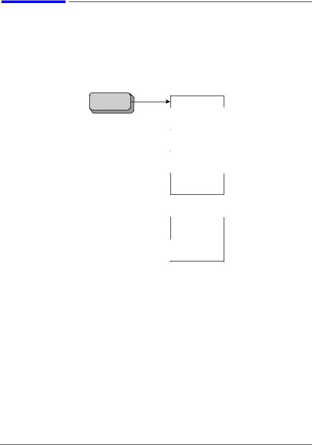
Figure 1-1 is an example mode menu map showing the N9061A (Remote Language Compatibility) application selection on your signal analyzer. To select the N9061A application, press the Mode hardkey on the X-Series analyzer front panel and then select the Remote Language Compatibility mode. If there are more than six modes on the signal analyzer, then use the More button to find the Remote Language Compatibility selection.
Figure 1-1 |
Example Mode Menu Map for X-Series Analyzers |
Mode
Spectrum
Analyzer
IQ Analyzer
(BASIC)
W-CDMA with
HSDPA/PSUPPA
Phase Noise
Remote
Language
Compatibility
27

Getting Started
Setting up N9061A on the X-Series Analyzer
Then, to select the legacy analyzer you wish to emulate, press the Mode Setup hardkey on the front panel. Figure 1-2 shows the menu map that allows you to select the 8560 series analyzer or 8566A/B, 8568A/B and therefore the remote control commands to be used in the X-Series analyzer.
Figure 1-2 |
Mode Setup > Legacy Instrument Selection Menu Map |
Mode Setup
Mode Setup
HP8560 series |
HP8563E/EC |
HP8566/68 |
HP8566B |
Cmd Error
On Off
Logging

Preferences

Restore Mode
Defaults
HP8566/68 |
HP8566A |
HP8566B |
HP8568A |
HP8568B |
Logging
Preferences
HP8560 Series |
HP8560E/EC |
HP8561E/EC |
HP8562E/EC |
HP8563E/EC |
HP8564E/EC |
HP8565E/EC |
The HP8560 series and HP8566A/B, 8568A/B key allow you to select which legacy instrument to emulate. The selected instrument determines the response to the “ID?” command and affects the behavior of commands such as IP. You can use any command offered by any of the legacy instruments regardless of the language setting. However, if the command is not correct for the selected legacy instrument there is no guarantee that the command will work as expected. This does not affect the response to the SCPI command “*IDN?”.
28

Getting Started
Setting up N9061A on the X-Series Analyzer
The legacy instrument selections are as follows:
8560E/EC |
Selects the 8560E/EC remote programming language and sets the response to the |
|
remote programming command ‘ID?’ to HP8560E. It also performs an instrument |
|
preset and sets Span, Trace Points, couplings, VBW/RBW ratio, and Span/RBW ratio |
|
appropriately as shown in Table 1-5. |
8561E/EC |
Selects the 8561E/EC remote programming language and sets the response to the |
|
remote programming command ‘ID?’ to HP8561E. It also performs an instrument |
|
preset and sets Span, Trace Points, couplings, VBW/RBW ratio, and Span/RBW ratio |
|
appropriately as shown in Table 1-5. |
8562E/EC |
Selects the 8562E/EC remote programming language and sets the response to the |
|
remote programming command ‘ID?’ to HP8562E. It also performs an instrument |
|
preset and sets Span, Trace Points, couplings, VBW/RBW ratio, and Span/RBW ratio |
|
appropriately as shown in Table 1-5. |
8563E/EC |
Selects the 8563E/EC remote programming language and sets the response to the |
|
remote programming command ‘ID?’ to HP8563E. It also performs an instrument |
|
preset and sets Span, Trace Points, couplings, VBW/RBW ratio, and Span/RBW ratio |
|
appropriately as shown in Table 1-5. This is the default setting for the N9061A |
|
application. |
8564E/EC |
Selects the 8564E/EC remote programming language and sets the response to the |
|
remote programming command ‘ID?’ to HP8564E. It also performs an instrument |
|
preset and sets Span, Trace Points, couplings, VBW/RBW ratio, and Span/RBW ratio |
|
appropriately as shown in Table 1-5. |
8565E/EC |
Selects the 8565E/EC remote programming language and sets the response to the |
|
remote programming command ‘ID?’ to HP8565E. It also performs an instrument |
|
preset and sets Span, Trace Points, couplings, VBW/RBW ratio, and Span/RBW ratio |
|
appropriately as shown in Table 1-5. |
HP8566A |
Selects the HP8566A remote programming language and sets the response to the |
|
remote programming command ‘ID?’ to HP8566A. It also performs an instrument |
|
preset and sets Span, Trace Points, couplings, VBW/RBW ratio, and Span/RBW ratio |
|
appropriately as shown in Table 1-5 on page 30. |
HP8566B |
Selects the HP8566B remote programming language and sets the response to the |
|
remote programming command ‘ID?’ to HP8566B. It also performs an instrument |
|
preset and sets Span, Trace Points, couplings, VBW/RBW ratio, and Span/RBW ratio |
|
appropriately as shown in Table 1-5 on page 30. |
HP8568A |
Selects the HP8568A remote programming language and sets the response to the |
|
remote programming command ‘ID?’ to HP8568A. It also performs an instrument |
|
preset and sets Span, Trace Points, couplings, VBW/RBW ratio, and Span/RBW ratio |
|
appropriately as shown in Table 1-5 on page 30. |
HP8568B |
Selects the HP8568B remote programming language and sets the response to the |
|
remote programming command ‘ID?’ to HP8568B. It also performs an instrument |
|
preset and sets Span, Trace Points, couplings, VBW/RBW ratio, and Span/RBW ratio |
|
appropriately as shown in Table 1-5 on page 30. |
29

Getting Started
Setting up N9061A on the X-Series Analyzer
NOTE |
Setting the remote language to anything other than ‘SCPI’ does not affect the |
||||||
|
response to the SCPI command ‘*IDN?’ This command will still return the model |
||||||
|
number and firmware version number of the X-Series signal analyzer. |
||||||
Table 1-5 |
Span, Trace Points, Couplings, VBW/RBW Ratio, and Span/RBW Ratio |
||||||
|
Settings |
|
|
|
|
|
|
|
|
|
|
|
|
|
|
Remote |
Start Freq. |
Stop |
Number of |
RF |
VBW/ |
Span/RBW |
|
Language |
|
Freq. |
Trace |
Coupling |
RBW |
Ratio |
|
|
|
|
Points |
|
Ratio |
|
|
|
|
|
|
|
|
|
|
8560E/EC |
30 Hz |
2.9 GHz |
601 |
AC |
1 |
91 |
|
|
|
|
|
|
|
|
|
8561E/EC |
30 Hz |
6.5 GHz |
601 |
AC |
1 |
91 |
|
|
|
|
|
|
|
|
|
8562E/EC |
30 Hz |
13.2 GHz |
601 |
AC |
1 |
91 |
|
|
|
|
|
|
|
|
|
8563E/EC |
30 Hz |
26.5 GHz |
601 |
DC |
1 |
91 |
|
|
|
|
|
|
|
|
|
8564E/EC |
30 Hz |
40 GHz |
601 |
DC |
1 |
91 |
|
|
|
|
|
|
|
|
|
8565E/EC |
30 Hz |
50 GHz |
601 |
DC |
1 |
91 |
|
|
|
|
|
|
|
|
|
HP8566A |
2 GHz |
22 GHz |
1001 |
DC |
3 |
106 |
|
|
|
|
|
|
(VBW |
|
|
|
|
|
|
|
one |
|
|
|
|
|
|
|
step |
|
|
|
|
|
|
|
wider |
|
|
|
|
|
|
|
than |
|
|
|
|
|
|
|
RBW) |
|
|
|
|
|
|
|
|
|
|
HP8566B |
2 GHz |
22 GHz |
1001 |
DC |
3 |
106 |
|
|
|
|
|
|
(VBW |
|
|
|
|
|
|
|
one |
|
|
|
|
|
|
|
step |
|
|
|
|
|
|
|
wider |
|
|
|
|
|
|
|
than |
|
|
|
|
|
|
|
RBW) |
|
|
|
|
|
|
|
|
|
|
HP8568A |
0 Hz |
1.5 GHz |
1001 |
DC |
3 |
106 |
|
|
|
|
|
|
(VBW |
|
|
|
|
|
|
|
one |
|
|
|
|
|
|
|
step |
|
|
|
|
|
|
|
wider |
|
|
|
|
|
|
|
than |
|
|
|
|
|
|
|
RBW) |
|
|
|
|
|
|
|
|
|
|
30
Loading...