


3C16896
Table of contents
 Loading...
http://www.3com.com/
3Com Family Switch 7750
Installation Guide
3C16896 8-slot AC Chassis
3C16897 8-slot DC Chassis
3C16895 7-slot Chassis
3C16894 4-slot Chassis
and associated modules
Part No. 10016428-AB
Published December 2007

3Com Corporation
350 Campus Drive
Marlborough, MA
01752-3064
Copyright © 2005, 2007 3Com Corporation. All rights reserved. No part of this documentation may be
reproduced in any form or by any means or used to make any derivative work (such as translation,
transformation, or adaptation) without written permission from 3Com Corporation.
3Com Corporation reserves the right to revise this documentation and to make changes in content from time
to time without obligation on the part of 3Com Corporation to provide notification of such revision or change.
3Com Corporation provides this documentation without warranty, term, or condition of any kind, either
implied or expressed, including, but not limited to, the implied warranties, terms or conditions of
merchantability, satisfactory quality, and fitness for a particular purpose. 3Com may make improvements or
changes in the product(s) and/or the program(s) described in this documentation at any time.
If there is any software on removable media described in this documentation, it is furnished under a license
agreement included with the product as a separate document, in the hard copy documentation, or on the
removable media in a directory file named LICENSE.TXT or !LICENSE.TXT. If you are unable to locate a copy,
please contact 3Com and a copy will be provided to you.
UNITED STATES GOVERNMENT LEGEND
If you are a United States government agency, then this documentation and the software described herein
are provided to you subject to the following:
All technical data and computer software are commercial in nature and developed solely at private expense.
Software is delivered as “Commercial Computer Software” as defined in DFARS 252.227-7014 (June 1995)
or
as a “commercial item” as defined in FAR 2.101(a) and as such is provided with only such rights as are
provided in 3Com’s standard commercial license for the Software. Technical data is provided with limited
rights only as provided in DFAR 252.227-7015 (Nov
1995) or FAR 52.227-14 (June 1987), whichever is
applicable. You agree not to remove or deface any portion of any legend provided on any licensed program
or documentation contained in, or delivered to you in conjunction with, this User Guide.
Unless otherwise indicated, 3Com registered trademarks are registered in the United States and may or may
not be registered in other countries.
3Com and the 3Com logo are registered trademarks of 3Com Corporation.
Intel and Pentium are registered trademarks of Intel Corporation. Microsoft, MS-DOS, Windows, and
Windows NT are registered trademarks of Microsoft
Corporation. UNIX is a registered trademark in the
United States and other countries, licensed exclusively through X/Open Company, Ltd.
IEEE and 802 are registered trademarks of the Institute of Electrical and Electronics Engineers, Inc.
All other company and product names may be trademarks of the respective companies with which they are
associated.
ENVIRONMENTAL STATEMENT
It is the policy of 3Com Corporation to be environmentally-friendly in all operations. To uphold our policy,
we are committed to:
Establishing environmental performance standards that comply with national legislation and regulations.
Conserving energy, materials and natural resources in all operations.
Reducing the waste generated by all operations. Ensuring that all waste conforms to recognized
environmental standards. Maximizing the recyclable and reusable content of all products.
Ensuring that all products can be recycled, reused and disposed of safely.
Ensuring that all products are labelled according to recognized environmental standards.
Improving our environmental record on a continual basis.
End of Life Statement
3Com processes allow for the recovery, reclamation and safe disposal of all end-of-life electronic components.
Regulated Materials Statement
3Com products do not contain any hazardous or ozone-depleting material.

CONTENTS
ABOUT THIS GUIDE
Conventions 5
Related Documentation 5
SWITCH 7750 COMPONENTS
Switch Chassis 7
Switch Backplane 7
Fabric Module 8
Fabric 32 Submodules 12
I/O Modules 14
Power Module 33
Power Distribution 33
External PoE Power System 33
Fan Assembly 34
Switch 7750 Specifications 35
INSTALLING THE SWITCH 7750
Preparing to Install 37
General Site Requirements 38
Installation Checklist 39
Installing the Chassis 40
Installing the Cabling Rack 40
Installing a Module 41
Installing a Submodule 41
Connecting the Ground Wire 42
Connecting and Configuring Power 42
Installing the Fan Assembly 45
Installing Cables 45
Installing Cabling 47
Post-installation Checklist 48
CONFIGURING THE SWITCH 7750
Configuring the Switch 7750 and a Local Terminal 49
Setting Terminal Parameters 49
Booting the Switch 7750 52

4 CONTENTS
MAINTAINING SOFTWARE
Upgrading Software 55
Lost Passwords 63
Using the BOOT Menu 63
TROUBLESHOOTING
Troubleshooting the Configuration 67
Troubleshooting Power 67
Troubleshooting the Fan 68
Troubleshooting the Modules 68
MAINTAINING HARDWARE
Replacing a Power Module 69
Replacing a Power Supply 70
Replacing I/O Modules 71
Replacing the Fan Assembly 71
OBTAINING SUPPORT FOR YOUR SWITCH
Register Your Product to Gain Service Benefits 73
Purchase Value-Added Services 73
Troubleshoot Online 73
Access Software Downloads 73
Contact Us 74
Telephone Technical Support and Repair 74
SWITCH 7750 CABLES
Console Cable 77
AUX Cable 77
Electrical Port Connector 78
Optical Fiber Cable Connectors 79
ABOUT THIS GUIDE
This guide describes the 3Com
®
Switch 7750 and how to install hardware,
configure and boot software, and maintain software and hardware. This guide
also provides troubleshooting and support information for your switch.
This guide is intended for qualified Service personnel who are responsible for
configuring, using, and managing the switches. It assumes a working knowledge
of local area network (LAN) operations and familiarity with communication
protocols that are used to interconnect LANs.
Always download the Release Notes for your product from the 3Com World Wide
Web site and check for the latest updates to software and product documentation
at
http://www.3com.com.
Conventions Ta bl e 1 lists icon conventions that are used throughout this guide.
Related
Documentation
The following manuals offer additional information necessary for managing your
Switch 7750:
■ Switch 7750 Command Reference Guide — Provides detailed descriptions of
command line interface (CLI) commands, that you require to manage your
Switch 7750.
■ Switch 7750 Configuration Guide— Describes how to configure your Switch
7750 using the supported protocols and CLI commands.
■ Switch 7750 Release Notes — Contains the latest information about your
product. If information in this guide differs from information in the release
notes, use the information in the Release Notes.
These documents are available in Adobe Acrobat Reader Portable Document
Format (PDF) on the 3Com World Wide Web site at
http://www.3com.com/.
Ta bl e 1 Notice Icons
Icon Notice Type Description
Information note Information that describes important features or
instructions.
Caution Information that alerts you to potential loss of data
or potential damage to an application, system, or
device.
Warning Information that alerts you to potential personal
injury.

6 ABOUT THIS GUIDE

1
SWITCH 7750 COMPONENTS
The chapter describes the following Switch 7750 components:
■ Switch Chassis
■ Switch Backplane
■ Fabric Module
■ Fabric 32 Submodules
■ I/O Modules
■ Power Module
■ Power Distribution
■ External PoE Power System
■ Fan Assembly
■ Switch 7750 Specifications
Switch Chassis The Switch 7750 is available with a 4-slot, 7-slot, or 8-slot chassis. Table 2 lists the
hardware features of each model.
Switch Backplane The Switch 7750 backplane is part of the integrated chassis and delivers
high-speed data transfer between the Fabric and I/O modules. The backplane
bandwidth capacity is 96 Gbps.
The backplane supports the following functions:
■ Interconnection of signals between modules
■ Provides communication channels
■ Hot swapping for modules
■ Automatic recognition of slots
■ Distribution of power and management of the power supply for the system
Ta bl e 2 Hardware Features of the Switch 7750 Models
4-Slot Chassis
3C16894
7-Slot Chassis
3C16895
8-Slot Chassis
AC 3C16896
DC 3C16897
Fabric slots 1 1 2
I/O module slots 3 6 6
Fan slot 1 1 2
AC/DC Power module
slots
2 3 3
8 CHAPTER 1: SWITCH 7750 COMPONENTS
Fabric Module There are three Fabric modules for the Switch 7750:
■ Fabric 64 (3C16857 or 3C16857R)
■ Fabric 32 (3C16872)
■ PoE Fabric 96 (3C16886)
The Fabric 64 and Fabric 32 are not interchangeable. You can install the Fabric 32
only in a 4-slot chassis. You can install the Fabric 64 only in the 7-slot or 8-slot
chassis. You can install the PoE Fabric 96 in all three chassis.
The Fabric module is the core of Switch 7750 system. It has the following
functions:
■ Connects the I/O modules through the backplane and forwards Layer 2 and
Layer 3 data
■ Manages and calculates routing
■ Performs the switch’s software upgrade and system reset functions
■ Monitors system power and the fan frame
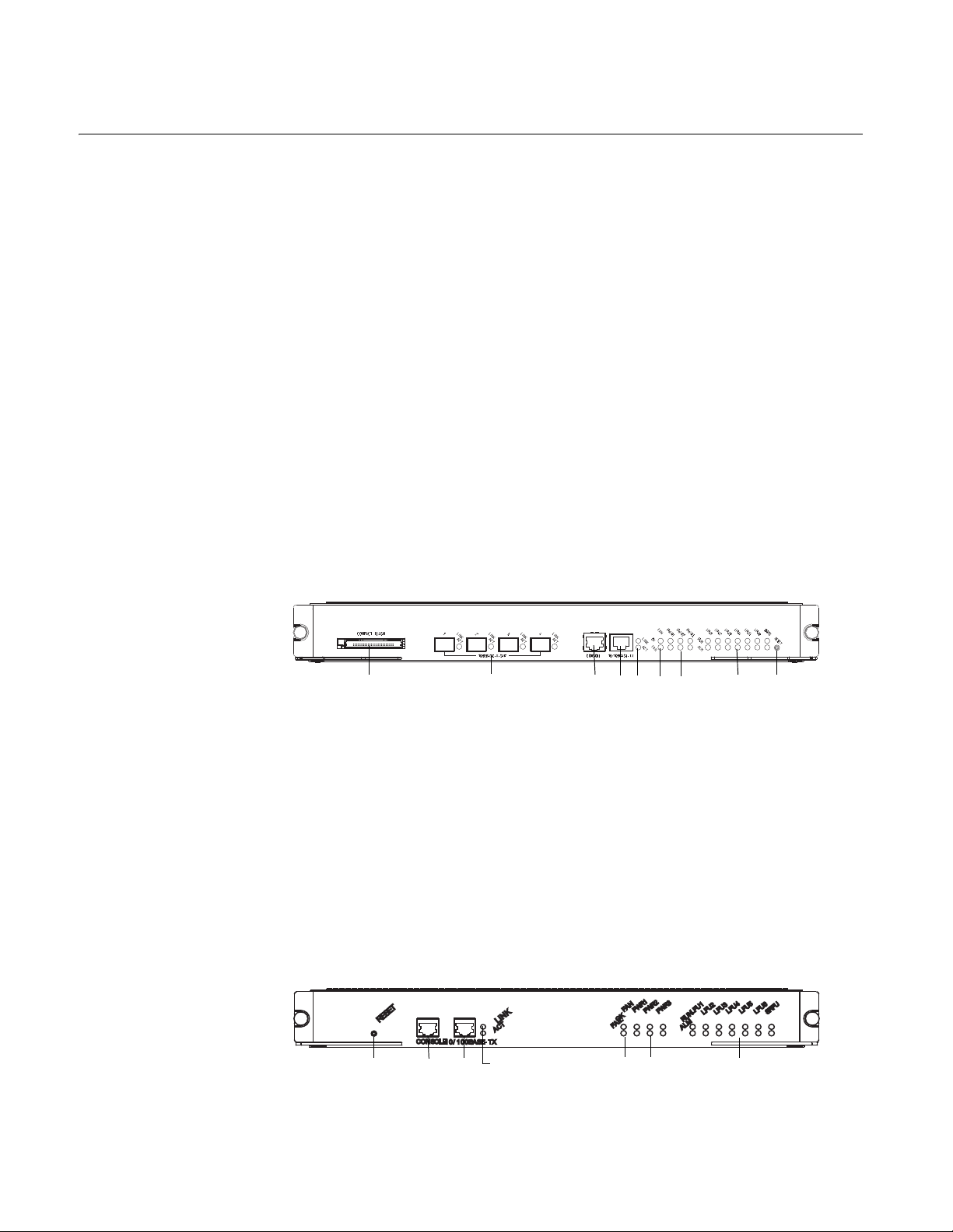
Figure 1 illustrates the front panel of the PoE Fabric 96.
Figure 1 PoE Fabric 96
1 Compact Flash port
2 1000BASE-X-SFP ports
3 Console port
4 Ethernet port
5 Ethernet port LEDs
6 Fan LEDs
7 Power LEDs
8 I/O module LEDs
9 Reset button
Figure 2 illustrates the front panel of the Fabric 64.
Figure 2 Fabric 64
1 Reset button
2 Console port
3 Ethernet port
4 Ethernet port LEDs
3C16886
1
2
3
45 6
7
8
9
3C16857
3C16857
1234
56
7
Fabric Module 9
5 Fan LEDs
6 Power module LEDs
7 I/O module LEDs
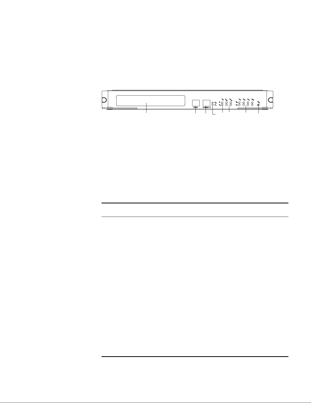
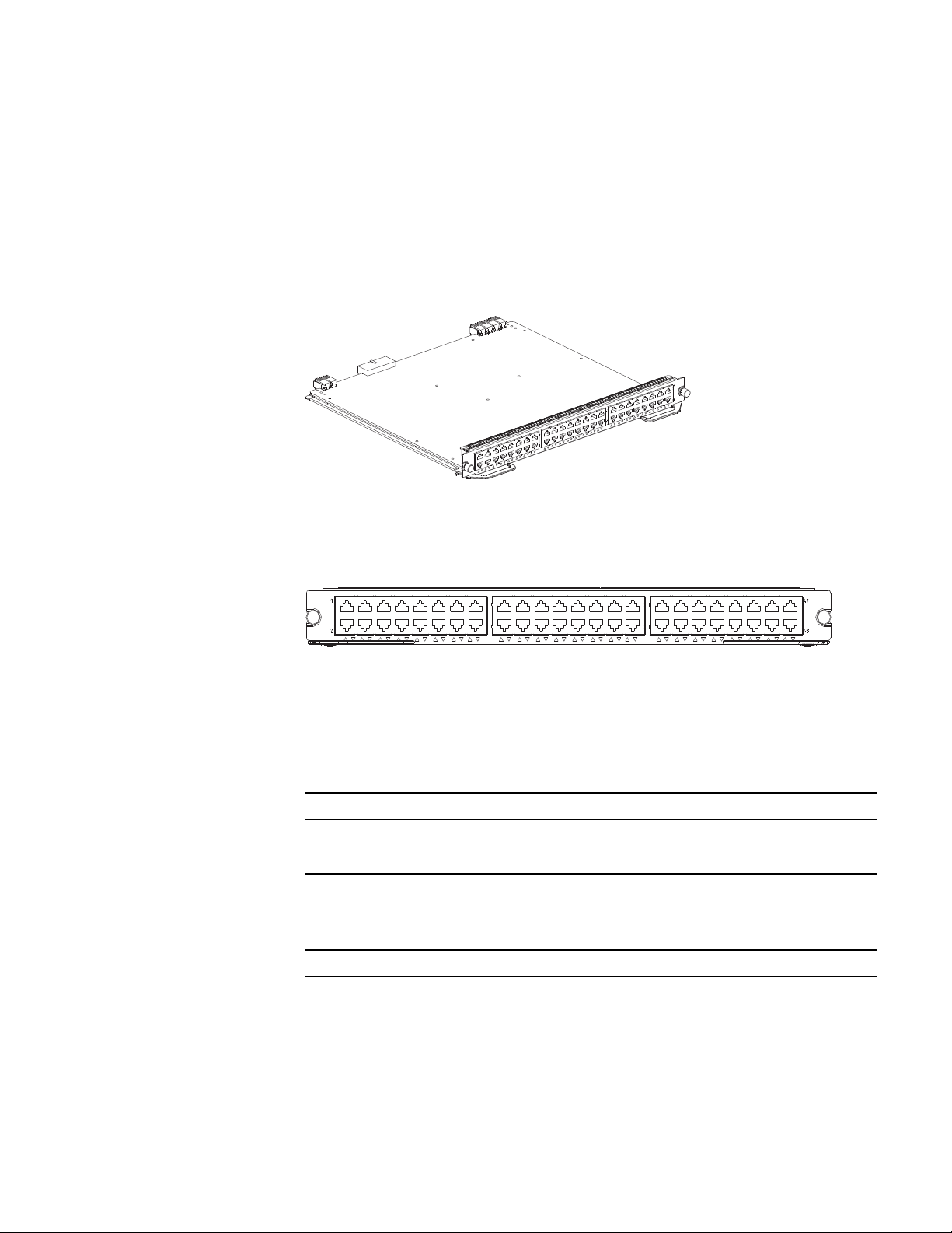
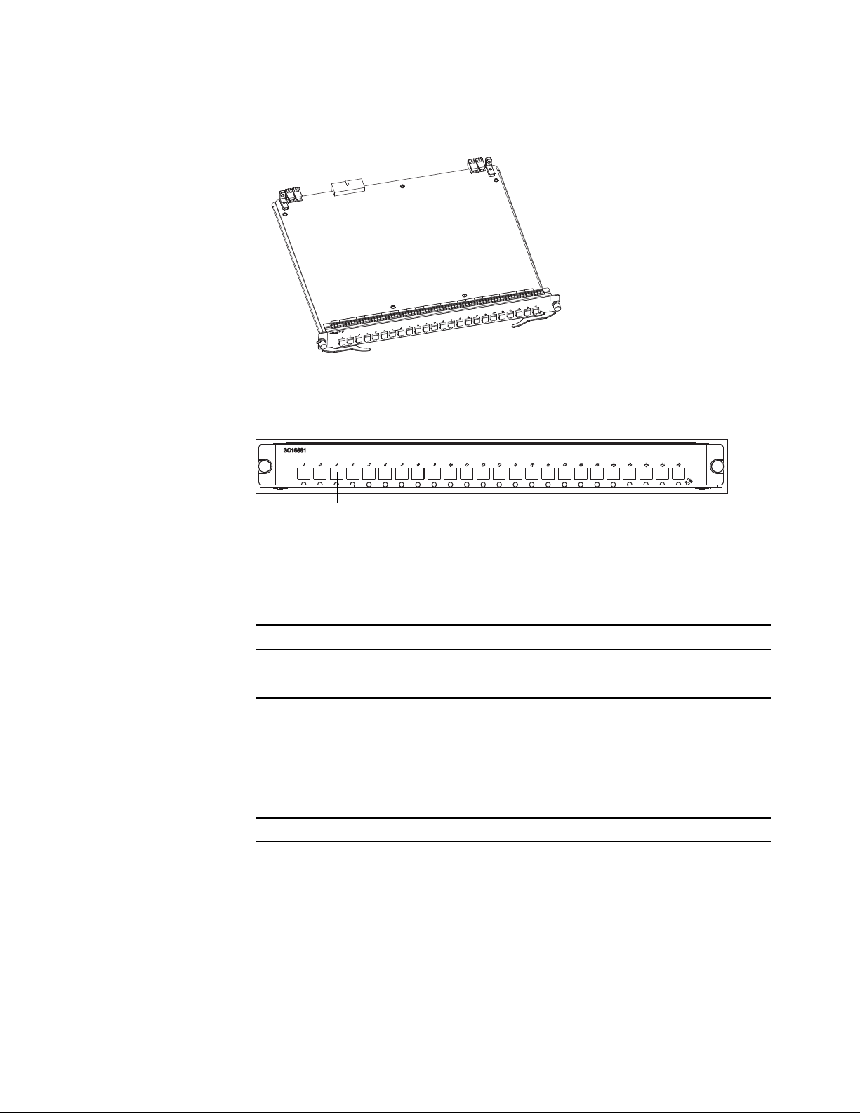
Figure 3 illustrates the front panel of the Fabric 32.
Figure 3 Fabric 32
1 Submodule slot
2 Console port
3 Ethernet port
4 Ethernet port LEDs
5 Fan LEDs
6 Power LEDs
7 I/O module LEDs
8 Reset button
Ta bl e 3 lists Fabric specifications.
Submodule Slot The submodule slot in the Fabric 32 offers extended Ethernet capacity using the
following submodules:
Ta bl e 3 Fabric Specifications
Item
PoE Fabric 96
(3C16886)
Fabric 64 (3C16857
or 3C16857R)
Fabric 32 (3C16872)
Bandwidth 96 Gbps 64 Gbps 32 Gbps
CPU MPC8245 MPC8260 200 Mhz
BootROM 512 KB 1 MB
SDRAM 256 M 256 MB
Flash 32 MB 16 MB
Submodule slot 1
Dimensions (L x W) 366.7 mm x 340 mm (14.5 x 13.5 in)
External ports One console port that supports local and remote dial-up configuration
management of the switch.
One 10BASE-T/100BASE-TX port for upgrade and network
management
One Compact Flash
port for storing log
and host version and
for online software
upgrades
Four 1000BASE-X-SFP
ports
Maximum power
consumption
80 W 80 W 70 W (with
submodule)
3C16872
3C16872
1234567
8

10 CHAPTER 1: SWITCH 7750 COMPONENTS
■ 4-port 1000BASE-X-GBIC submodule
■ 4-port 10/100/1000BASE-T submodule
For more information on these submodules, see “Fabric 32 Submodules”on
page 12.
Fixed Ports The Switch 7750 Fabric modules provide the following fixed ports:
■ Compact Flash (CF) Port
■ 1000BASE-X-SFP (PoE Fabric 96 only)
■ Console Port
■ Ethernet Port
Compact Flash (CF) Port
The Fabric module provides a CF port to accommodate a standard CF card, where
you can save logging information, host version information, alarming and other
diagnostic information. You can also use the CF port to upgrade software online.
1000BASE-X-SFP Ports
The PoE Fabric 96 provides four 1000 Mbps full-duplex SFP ports. Table 4 describes
the SFP cables for these ports.
Ta bl e 8 describes the LEDs of the SFP ports.
Ta bl e 4 Cables for 1000BASE-T-SFP Modules
SFP Module
Central
Wavelength
Connector Matching Cable
Maximum
transmission
distance
1000BASE-SX-SFP 850 nm LC 50/125 µm
multimode
optical fiber
cable
550 m (1804 ft.)
62/125 µm
multimode
optical fiber
cable
275 m (902 ft.)
1000BASE-LX-SFP 1310 nm 9/125 µm single
mode optical
fiber cable
10 km (6 mi.)
1000BASE-LH-SFP 30 km (19 mi.)
1000BASE-ZX-LR-SFP 1550 nm 40 km (25 mi.)
1000BASE-ZX-VR-SFP 70 km (43 mi.)
1000BASE-T-FD-SFP RJ-45 100 m (328 ft.)
Ta bl e 5 SFP Port LEDs
LED Description
LINK/ACT Off — The line is not connected.
Green — The line is connected.
Green flashing — Data is being transmitted or received.

Fabric Module 11
Console Port
The console port is connected to the configuration terminal using an RJ-45
connector. You can use the console port for system debugging, configuration,
maintenance, management, and loading application files.
The console port can also be connected to a modem for functions such as remote
system debugging, configuration, maintenance, and management. You can
configure the baud rate on the console port.
Ta bl e 6 lists console port specifications.
Ethernet Port
The Ethernet port on the Fabric is connected to a computer using an RJ-45
connector. You can use the Ethernet port for system application downloading and
debugging. The Ethernet port can also be connected to devices such as a network
management workstation to manage the system remotely.
Ta bl e 7 lists Ethernet port specifications.
See “Electrical Port Connector” on page 78 for an illustration of the RJ-45
connector and MDI/MDI-X pinout details.
Ta bl e 8 describes the LEDs of the Ethernet port.
Ta bl e 6 Console Port Specifications
Specification Description
Port connector RJ-45
Port standard Asynchronous EIA/TIA-232
Baud rate 9600 bps (by default)
Transmission distance 15 m (45 ft)
Services Connects with character terminal
Connects with local or remote PC serial port and runs terminal
emulation on a PC (a pair of modems are required for a
remote connection)
Ta bl e 7 Ethernet Port Specifications
Specification Description
Port connector RJ-45
Number of port(s) 1
Port speed 10 Mbps, half/full duplex
100 Mbps, half/full duplex
MDI/MDIX auto sensing
Cable and maximum transmission
distance
Category-5 twisted pair for transmission within 100 m
(328 ft)
Port function Switch software upgrade and network management
Ta bl e 8 Ethernet Port LEDs
LED Description
LINK Off — The line is not connected.
Green — The line is connected.

12 CHAPTER 1: SWITCH 7750 COMPONENTS
Module LEDs The module LEDs show the status of the I/O modules, as described in Table 9.
Power LEDs PWR1, PWR2, and PWR3 LEDs show the status of the power modules, as
described in
Ta bl e 10.
Fan LED Fan LEDs show the status of the fan frame, as described in Table 11.
Reset Button The reset button resets the entire system.
Fabric 32 Submodules The Fabric 32 provides a slot for one submodule. The Fabric 32 supports the
following submodules:
■ 4-Port 1000BASE-X-GBIC Submodule (3C16874)
■ 4-Port 10/100/1000BASE-T Submodule (3C16873)
4-Port 1000BASE-X-GBIC
Submodule
The 4-port 1000BASE-X-GBIC submodule provides four GE full-duplex Ethernet
GBIC ports.
Figure 4 illustrates the 4-port 1000BASE-X-GBIC submodule.
ACTIVE Green — No data is being transmitted or received.
Green flashing — Data is being transmitted or received.
Table 8 Ethernet Port LEDs (continued)
LED Description
Ta bl e 9 I/O Module LEDs
LED Status description
RUN Green or off — The module failed or has not been inserted.
Green flashing — The module is working normally.
ALM Off — The module is working normally or has not been
inserted.
Green or green flashing — The module failed or is not
working normally.
Ta bl e 10 Power LEDs
LED Description
OK Green — The corresponding power module is working
normally.
Off — The corresponding power module is not working or
has not been installed.
FAIL Green — The corresponding power module is not working.
Off — The corresponding power module works normally or
has not been installed.
Ta bl e 11 Fan LEDs
LED Description
OK Green — The fan is working normally.
Off — The fan is not working or has not been installed.
FAIL Green — The fan is not working.
Off — The fan is working normally or has not been installed.
Fabric 32 Submodules 13
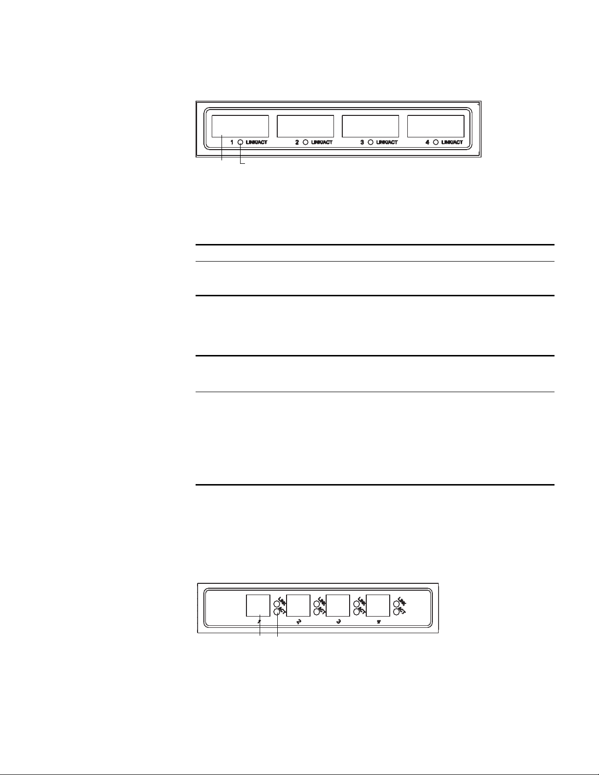
Figure 4 4-Port 1000BASE-X-GBIC Submodule
Ethernet GBIC port
2 Ethernet GBIC port LED
Ta bl e 12 describes the 4-port 1000BASE-X-GBIC submodule LEDs.
Ta bl e 13 lists the specifications for each of the 4-port 1000BASE-X-GBIC
submodule.
4-Port
10/100/1000BASE-T
Submodule
The 4-Port 10/100/1000BASE-T submodule provides four 10/100/1000 Mbps
auto-negotiation service ports.
Figure 5 illustrates the 4-port 10/100/1000BASE-T submodule.
Figure 5 4-Port 10/100/1000BASE-T Submodule
1 Ethernet port
2 Ethernet port LEDs
Ta bl e 12 4-Port 1000BASE-X-GBIC Submodule LEDs
LED Description
LINK/ACT Green — The link is operating normally.
Off — The link is not operating.
Green flashing — Data is being transmitted or received.
Ta bl e 13 4-Port 1000BASE-X-GBIC Submodule Specifications
Optional GBIC
Module
Central
Wavelength
Connector
Type
Interface Fiber
Specifications
Max.
Transmission
Distance
1000BASE-SX-MM
(3CGBIC91)
850 nm SC 50/125 µm
multi-mode fiber
62.5/125 µm
Multi-mode fiber
500 m (1640 ft)
220 m (722 ft)
1000BASE-LX-SM-IR
(3CGBIC92)
1310 nm SC 9/125 µm
Single-mode fiber
10 km (6 mi)
1000BASE-LX-SM
(3CGBIC97)
1550 nm SC 9/125 µm
Single-mode fiber
40 km (25 mi)
70 km (43.5 mi)
3C16874
12
3C16873
3C16873
12

14 CHAPTER 1: SWITCH 7750 COMPONENTS
Ta bl e 14 describes the 4-port 10/100/1000BASE-T submodule LEDs.
Ta bl e 15 lists specifications of the 4-port 10/100/1000BASE-T submodule.
See “Electrical Port Connector” on page 78 for an illustration of the RJ-45
connector and MDI/MDI-X pinout details.
I/O Modules The Switch 7750 provides multiple slots for I/O modules below the Fabric slots.
The following I/O modules are supported:
■ 48-port 10/100BASE-T FE PoE Module (3C16891)
■ 48-port 10/100/1000BASE-T PoE Module (3C16890)
■ 48-port 10/100BASE-TX FE Module (3C16889)
■ 48-port 10/100/1000BASE-T Module (3C16888)
■ 48-port 100BASE-X SFP Module
■ 20-Port 10/100/1000BASE-T Module (3C16863A)
■ 20-Port 1000BASE-X-SFP Module (3C16862A)
■ 12-port 10/100/1000BASE-T and 4-port 1000BASE-X SFP Module (3C168916)
■ 12-port 1000BASE-X SFP and 4-port 10/100/1000BASE-T Module (3C186917)
■ 8-port 1000BASE-X GBIC Module (3C16858)
■ 8-port 10/100/1000BASE-T GE Module (3C16859)
■ 100Base-FX SFP mode (3C16865915)
Consider the following when selecting I/O modules:
■ You can configure several I/O modules of the same type
■ Any combination of I/O modules can be inserted but only PoE I/O modules
provide the features of power over Ethernet.
Ta bl e 14 4-Port 10/100/1000BASE-T Submodule LEDs
LED Description
LINK Off — The link is not operating.
On — The link is operating normally.
ACT Off — No data is being transmitted or received.
Green flashing — Data is being transmitted or received.
Ta bl e 15 4-Port 10/100/1000BASE-T Submodule Specifications
Specification Description
Connector type RJ-45
Number of ports 4
Port speed 1000 Mbps full duplex
100 Mbps half/full duplex
10 Mbps half/full duplex
MDI/MDI-X auto-sensing
Cable and maximum
transmission distance
Category 5 twisted pair up to 100 m (328 ft)
I/O Modules 15
■ You must select I/O module port cables that are compatible with each installed
I/O module
48-port 10/100BASE-T FE
PoE Module
The 48-port 10/100BASE-T FE PoE module provides 48 10/100 Mbps auto-sensing
Ethernet ports that provide a remote power supply to powered devices
Figure 12illustrates the 48-port 10/100BASE-T FE PoE module.
Figure 6 48-port 10/100BASE-T FE PoE Module
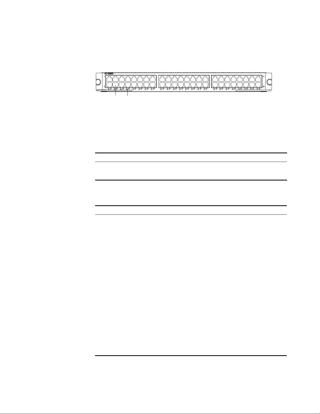
Figure 13 illustrates the front panel and LEDs of the 48-port 10/100BASE-T FE PoE
module.
Figure 7 Front Panel of the 48-port 10/100BASE-T FE PoE Module
1 Ethernet port
2 Ethernet port LED
Ta bl e 22 describes the 48-port 10/100BASE-T FE PoE Module LEDs.
Ta bl e 23 describes the specifications for the 48-port 10/100BASE-T FE PoE module.
Ta bl e 16 module LED
LED Description
LINK/ACT Green — The port is connected.
Off — The port is not connected.
Green flashing — Data is being transmitted or received.
Ta bl e 17 Specifications for the 48-port 10/100BASE-T FE PoE Module
Specification Description
CPU MPC8241
BootROM 512 KB
SDRAM 128 M
Dimensions (L X W) 366.7 x 340 mm (14.4 x 13.4 in.)
Maximum power consumption 35 W
Connector RJ-45
Number of ports 48
3C16891
3C16891
1
2

16 CHAPTER 1: SWITCH 7750 COMPONENTS
48-port
10/100/1000BASE-T PoE
Module
The 48-port 10/100/1000BASE-T PoE module provides 48 10/100/1000 Mbps
auto-sensing Ethernet ports that provide a remote power supply to powered
devices.
Figure 12illustrates the 48-port 10/100/1000BASE-T PoE module.
Figure 8 48-port 10/100/1000BASE-T PoE Module
Figure 13 illustrates the front panel and LEDs of the 48-port 10/100/1000BASE-T
PoE module.
Figure 9 Front Panel of the 48-port 10/100/1000BASE-T PoE Module
1 Ethernet port
2 Ethernet port LED
Port transmission speed 10/100 Mbps half-/full-duplex MDI/MDI-X auto-sensing
Cables and maximum
transmission distance
100 m (328 ft.)
Maximum power each port
provides
15.4 W
Compliance IEEE802.3
IEEE802.3u
IEEE802.3x
IEEE802.3ad
IEEE802.1p
IEEE802.1D
IEEE802.1Q
IEEE802.1X
IEEE802.1s
IEEE802.1w
IEEE802.3af
Table 17 Specifications for the 48-port 10/100BASE-T FE PoE Module (continued)
Specification Description
3C16890
3C16890
12

I/O Modules 17
Ta bl e 22 describes the 48-port 10/100/1000BASE-T PoE module LEDs.
Ta bl e 23 describes the specifications of the 48-port 10/100/1000BASE-T PoE
module.
48-port 10/100BASE-TX
FE Module
The 48-port 10/100BASE-TX FE module provides 48 10/100 Mbps auto-sensing
Ethernet electrical ports.
Figure 10 illustrates the 48-port 10/100BASE-T FE module.
Figure 10 48-port 10/100BASE-T FE Module
Ta bl e 18 48-port 10/100/1000BASE-T PoE Module LED
LED Description
LINK/ACT Green — The port is connected.
Off — The port is not connected.
Green flashing — Data is being transmitted or received.
Ta bl e 19 Specifications for the 48-port 10/100/1000BASE-T PoE Module
Specification Description
CPU MPC8241
BootROM 512 KB
SDRAM 128 M
Dimensions (L X W) 366.7 x 340 mm (14.4 x 13.4 in.)
Maximum power consumption 70 W
Connector RJ-45
Number of ports 48
Port transmission speed 10/100/1000 Mbps half-/full-duplex
MDI/MDIX auto-sensing
Cables and maximum
transmission distance
Category 5 twisted pair with a maximum distance of 100 m
(328 ft.)
Compliance IEEE802.3ab
IEEE802.3
IEEE802.3i
IEEE802.3x
IEEE802.1p
IEEE802.1D
IEEE802.1Q
IEEE802.1X
IEEE802.1s
IEEE802.1w
18 CHAPTER 1: SWITCH 7750 COMPONENTS
Figure 11 illustrates the front panel and LEDs of the 48-port 10/100BASE-TX FE
module.
Figure 11 Front Panel of the 48-Port 10/100BASE-TX FE module
1 Ethernet port
2 Ethernet port LED
Each 100 Mbps Ethernet port has a green LED, indicating LINK/ACTIVE status.
Ta bl e 20 describes the 48-port 10/100BASE-TX FE module LED.
Ta bl e 21 describes the specifications of the 48-port 10/100BASE-TX FE module.
See “Electrical Port Connector” on page 78 for an illustration of the RJ-45
connector and MDI/MDI-X pinout details.
Ta bl e 20 48-Port 10/100BASE-TX FE module LED
LED Description
LINK/ACT Green — The port is connected.
Off — The port is not connected.
Green flashing — Data is being transmitted or received.
Ta bl e 21 Specifications for the 48-Port 10/100BASE-TX FE Module
Specification Description
CPU MPC850
BootROM 512 KB
SDRAM 64 MB
Dimensions (L X W) 366.7 x 340 mm (14.5 x 13.4 in)
Maximum power
consumption
75 W
Connector RJ-45
Number of ports 48
Port transmission
speed
10/100 Mbps half/full duplex
MDI/MDIX auto-sensing
Cables and maximum
transmission distance
Cables are 2 100-ohm Category-5 twisted pairs up to 100 m (300 ft).
Compliance IEEE802.3
IEEE802.3u
IEEE802.3x
IEEE802.3ad
IEEE802.1p
IEEE802.1D
IEEE802.1Q
IEEE802.1X
IEEE802.1s
IEEE802.1w
12
I/O Modules 19
48-port
10/100/1000BASE-T
Module
The 48-port 10/100/1000BASE-T module provides 48 10/100/1000 Mbps
auto-sensing Ethernet electrical ports.
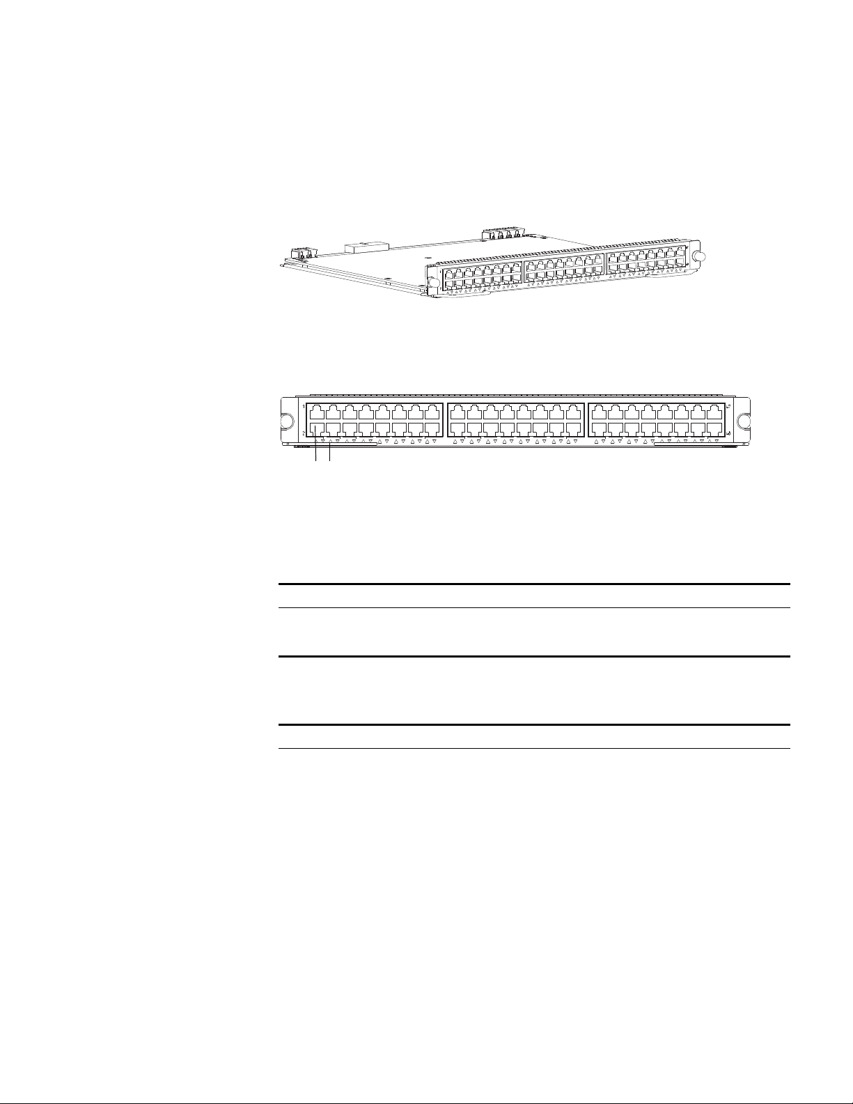
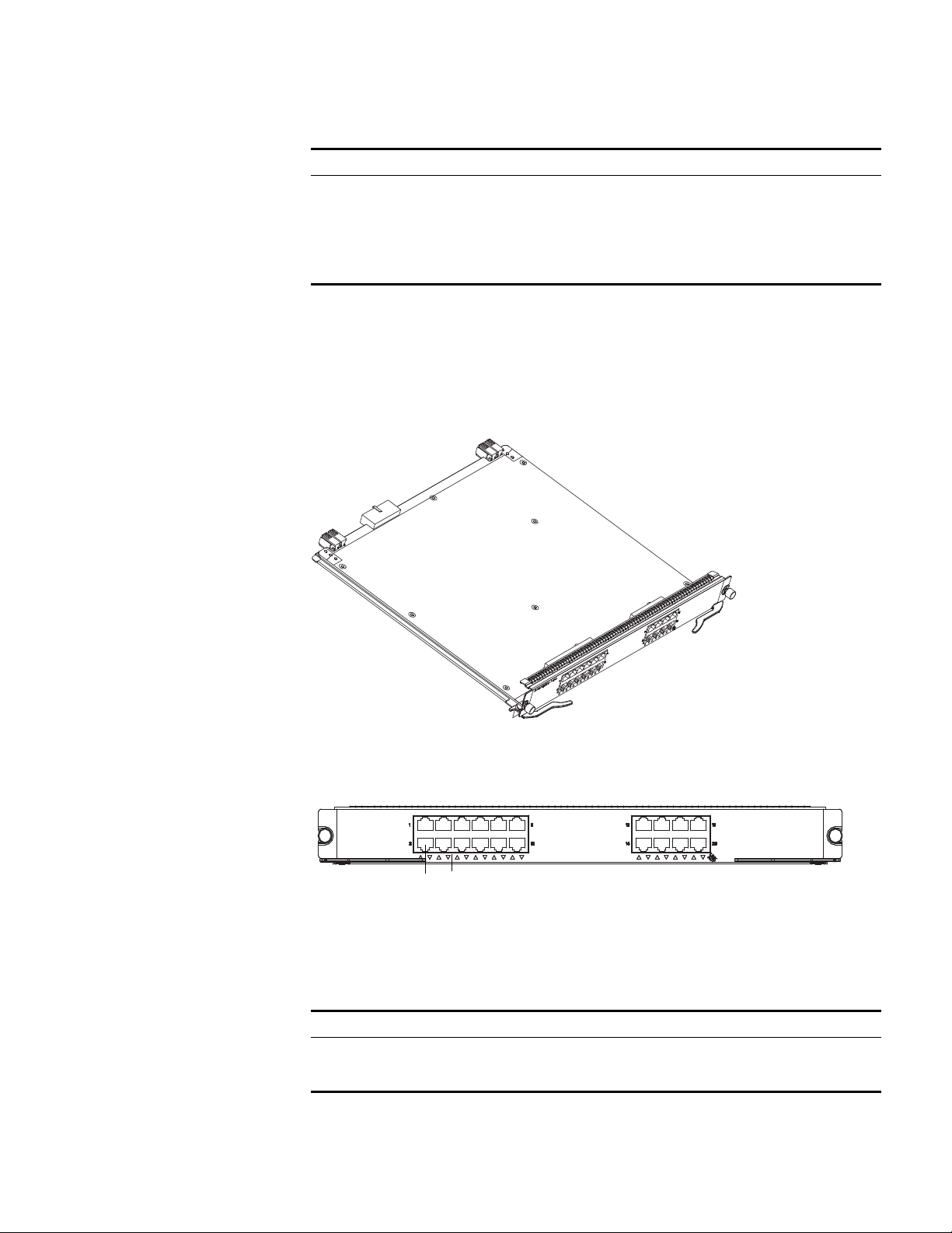
Figure 12 illustrates the 48-port 10/100/1000BASE-T module.
Figure 12 48-port 10/100/1000BASE-T Module
Figure 13 illustrates the front panel and LEDs of the 48-port 10/100/1000BASE-T
module.
Figure 13 Front Panel of the 48-port 10/100/1000BASE-T Module
1 Ethernet port
2 Ethernet port LED
Ta bl e 22 describes the 48-port 10/100/1000BASE-T module LEDs.
Ta bl e 23 describes the specifications of the 48-port 10/100/1000BASE-T module.
Ta bl e 22 48-port 10/100/1000BASE-T Module LED
LED Description
LINK/ACT Green — The port is connected.
Off — The port is not connected.
Green flashing — Data is being transmitted or received.
Ta bl e 23 Specifications for the 48-port 10/100/1000BASE-T Module
Specification Description
CPU MPC8241
BootROM 512 KB
SDRAM 128 M
Dimensions (L X W) 366.7 x 340 mm (14.4 x 13.4 in.)
Maximum power consumption 70 W
Connector RJ-45
Number of ports 48
Port transmission speed 10/100/1000 Mbps half-/full-duplex MDI/MDI-X
auto-sensing
Cables and maximum
transmission distance
Category 5 twisted pair with a maximum transmission
distance of 100 m (328 ft.)
3C16888
12
3C16888
20 CHAPTER 1: SWITCH 7750 COMPONENTS
48-port 100BASE-X SFP
Module
The 48-port 100BASE-X SFP module provides 48 100 Mbps full-duplex Ethernet
optical ports.
Figure 14 illustrates the 48-port 100BASE-X SFP module.
Figure 14 48-port 48-port 100BASE-X SFP Module
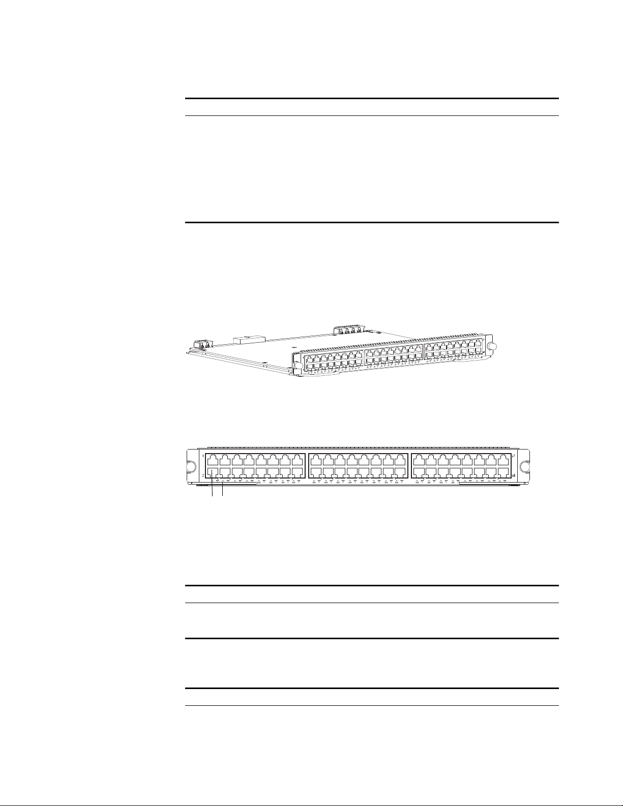
Figure 15 illustrates the front panel and LEDs of the 48-port 100BASE-X SFP
module.
Figure 15 Front Panel of the 48-port 48-port 100BASE-X SFP Module
1 Ethernet port
2 Ethernet port LED
Ta bl e 24 describes the 48-port 100BASE-X SFP module LEDs.
Ta bl e 25 describes the specifications of the 48-port 100BASE-X SFP module.
Compliance 1EEE 802.3ab
1EEE 802.3
1EEE 802.3u
1EEE 802.3x
1EEE 802.1p
1EEE 802.1D
1EEE 802.1Q
1EEE 802.1X
1EEE 802.1s
1EEE 802.1w
Table 23 Specifications for the 48-port 10/100/1000BASE-T Module (continued)
Specification Description
Ta bl e 24 48-port 100BASE-X SFP Module LED
LED Description
LINK/ACT Green — The port is connected.
Off — The port is not connected.
Green flashing — Data is being transmitted or received.
Ta bl e 25 Specifications for the 48-port 100BASE-X SFP Module
Specification Description
CPU MPC8241
BootROM 512 KB
SDRAM 128 M
3C16888
12
3C16888

I/O Modules 21
Ta bl e 26 lists the cables for the 48-port 100BASE-X (SFP) ports
24-port 100BASE-FX
MMF FE Module
The 24-port 100BASE-FX MMF FE module provides 24 100 Mbps multi-mode
Ethernet optical port service channels.
Figure 16 illustrates the 24-port 100BASE-FX MMF FE module.
Dimensions (L X W) 366.7 x 340 mm (14.4 x 13.4 in.)
Maximum power consumption 36.5 W
Connector LC
Number of ports 48
SFP module 100BASE-FX-MM-SFP
100BASE-FX-SM-SFP
100BASE-FX-SM-LR-SFP
100BASE-FX-SM-VR-SFP
Port transmission speed 100 Mbps full-duplex
Compliance 1EEE 802.3
1EEE 802.3u
1EEE 802.3x
1EEE 802.3ad
1EEE 802.1p
1EEE 802.1D
1EEE 802.1Q
1EEE 802.1X
1EEE 802.1s
1EEE 802.1w
Ta bl e 26 Cables for the 48-port 100BASE-X SFP Module
SFP module
Central
wave-
length Connector Matching cable
Maximum
transmission
distance
100BASE-FX-MM-SFP 1310nm LC multimode optical fiber
cable
2 km (1.2 mi)
100BASE-FX-SM-SFP 1310nm 15 km (9.3 mi)
100BASE-FX-SM-LR-S
FP
1310nm 9/125 µm single mode
optical fiber cable
40 km (24.9 mi)
100BASE-FX-SM-VR-S
FP
1550nm 70km (43 mi)
Table 25 Specifications for the 48-port 100BASE-X SFP Module (continued)
Specification Description
22 CHAPTER 1: SWITCH 7750 COMPONENTS
Figure 16 24-Port 100BASE-FX MMF FE Module
Each 100 Mbps optical port has a green LED, as shown in Figure 17.
Figure 17 Front Panel of the 24-Port 100BASE-FX MMF FE Module
1 Ethernet port
2 Ethernet port LED
Ta bl e 27 describes the status of the 24-port 100BASE-FX MMF FE module LEDs.
The 24-port 100BASE-FX MMF FE module requires a 62.5/125 µm multi-mode
optical fiber cable with an MT-RJ connector and a central wavelength of 1300 nm.
Ta bl e 28 describes the specifications of the 24-port 100BASE-FX MMF FE module.
Ta bl e 27 24-Port 100BASE-FX MMF FE Module LEDs
LED Description
LINK/ACT Green — The port is connected.
Off — The port is not connected.
Green flashing — Data is being transmitted or received.
Ta bl e 28 Specifications for the 24-Port 100BASE-FX MMF FE Module
Specification Description
CPU MPC850
BootROM 512 KB
SDRAM 64 MB
Dimensions (L x W) 366.7 x 340 mm (14.5 x 13.4 in)
Maximum power
consumption
55 W
Connector type MT-RJ
Number of ports 24
Port transmission speed 100 Mbps, full-duplex
1
2
I/O Modules 23
20-Port
10/100/1000BASE-T
Module
The 20-Port 10/100/1000BASE-T module provides 20 10/100/1000BASE-T
auto-sensing Ethernet ports.
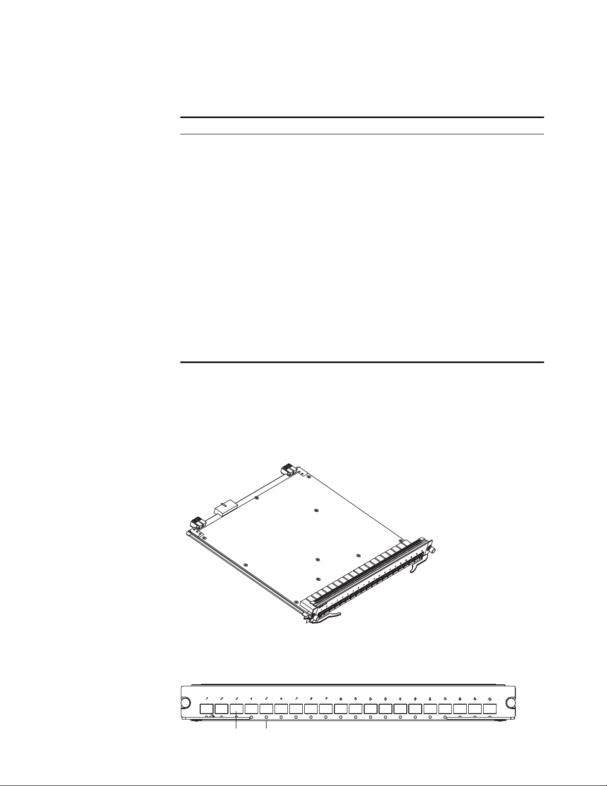
Figure 18 illustrates the 20-Port 10/100/1000BASE-T Module.
Figure 18 20-Port 10/100/1000BASE-T Module
Figure 19 illustrates the front panel of the 20-port 10/100/1000BASE-T module.
Figure 19 Front Panel of the 20-Port 10/100/1000BASE-T Module
1 Ethernet port
2 Ethernet port LED
Ta bl e 29 describes the 20-port 10/100/1000BASE-T module LEDs.
Cables and maximum
transmission distance
62.5/125 µm multi-mode optical fiber up to 2 km (1.3 mi)
Compliance IEEE 802.3
IEEE 802.3i
IEEE 802.3u
IEEE 802.3x
Table 28 Specifications for the 24-Port 100BASE-FX MMF FE Module (continued)
Specification Description
Ta bl e 29 20-Port 10/100/1000BASE-T Module LEDs
LED Description
LINK/ACT Off — The port is not operating.
On — The port is operating.
Green flashing — The port is transmitting or receiving data
3C16863
3C16863
12
24 CHAPTER 1: SWITCH 7750 COMPONENTS
Ta bl e 30 lists specifications of the 20-port 10/100/1000BASE-T module.
20-Port 1000BASE-X-SFP
Module
The 20-port 1000BASE-X-SFP module provides 20 1000 BASE-X full duplex ports
and uses an SFP cable.
Figure 20 illustrates the 20-port 1000BASE-X-SFP module.
Figure 20 20-Port 1000BASE-X-SFP Module
Figure 21 illustrates the front panel of the 20-port 1000BASE-X-SFP module.
Figure 21 Front Panel of the 20-Port 1000BASE-X-SFP Module
Ta bl e 30 Specifications for the 20-Port 10/100/1000BASE-T Module
Specification Description
CPU MPC8241LZU200
BootROM 512 KB
SDRAM 64 MB
Dimensions (L x W) 366.7 x 340 mm (14.5 x 13.4 in)
Power consumption 45 W
Connector RJ-45
Number of ports 20
Transmission rate 10 Mbps half/full duplex
100 Mbps half/full duplex
1000 Mbps full duplex
Cable and maximum
transmission distance
Category-5 twisted pair
100 m (300 ft)
Compliance IEEE 802.3ab
IEEE 802.3
IEEE 802.3u
IEEE 802.3x
IEEE 802.1D
IEEE 802.1Q
3C168623C16862
12
Loading...