


 Loading...
3Com® Switch 4200G Family
Getting Started Guide
4200G 12-Port (3CR17660-91)
4200G 24-Port (3CR17661-91)
4200G 48-Port (3CR17662-91)
www.3Com.com
Part No. 10014914 Rev. AA
Published July 2006
3Com Corporation
350 Campus Drive
Marlborough,
MA 01752-3064
Copyright © 2006, 3Com Corporation. All rights reserved. No part of this documentation may be reproduced in any form or by any means or used to make any derivative work (such as translation, transformation, or adaptation) without written permission from 3Com Corporation.
3Com Corporation reserves the right to revise this documentation and to make changes in content from time to time without obligation on the part of 3Com Corporation to provide notification of such revision or change.
3Com Corporation provides this documentation without warranty, term, or condition of any kind, either implied or expressed, including, but not limited to, the implied warranties, terms or conditions of merchantability, satisfactory quality, and fitness for a particular purpose. 3Com may make improvements or changes in the product(s) and/or the program(s) described in this documentation at any time.
If there is any software on removable media described in this documentation, it is furnished under a license agreement included with the product as a separate document, in the hard copy documentation, or on the removable media in a directory file named LICENSE.TXT or !LICENSE.TXT. If you are unable to locate a copy, please contact 3Com and a copy will be provided to you.
UNITED STATES GOVERNMENT LEGEND
If you are a United States government agency, then this documentation and the software described herein are provided to you subject to the following:
All technical data and computer software are commercial in nature and developed solely at private expense. Software is delivered as “Commercial Computer Software” as defined in DFARS 252.227-7014 (June 1995) or as a “commercial item” as defined in FAR 2.101(a) and as such is provided with only such rights as are provided in 3Com’s standard commercial license for the Software. Technical data is provided with limited rights only as provided in DFAR 252.227-7015 (Nov 1995) or FAR 52.227-14 (June 1987), whichever is applicable. You agree not to remove or deface any portion of any legend provided on any licensed program or documentation contained in, or delivered to you in conjunction with, this User Guide.
Unless otherwise indicated, 3Com registered trademarks are registered in the United States and may or may not be registered in other countries.
3Com and the 3Com logo are registered trademarks of 3Com Corporation.
ntel and Pentium are registered trademarks of Intel Corporation. Microsoft, MS-DOS, Windows, and Windows NT are registered trademarks of Microsoft Corporation. Novell and NetWare are registered trademarks of Novell, Inc. UNIX is a registered trademark in the United States and other countries, licensed exclusively through X/Open Company, Ltd.
IEEE and 802 are registered trademarks of the Institute of Electrical and Electronics Engineers, Inc.
All other company and product names may be trademarks of the respective companies with which they are associated.
ENVIRONMENTAL STATEMENT
It is the policy of 3Com Corporation to be environmentally friendly in all operations. To uphold our policy, we are committed to:
Establishing environmental performance standards that comply with national legislation and regulations.
Conserving energy, materials and natural resources in all operations.
Reducing the waste generated by all operations. Ensuring that all waste conforms to recognized environmental standards. Maximizing the recyclable and reusable content of all products.
Ensuring that all products can be recycled, reused and disposed of safely.
Ensuring that all products are labelled according to recognized environmental standards.
Improving our environmental record on a continual basis.
End of Life Statement
3Com processes allow for the recovery, reclamation and safe disposal of all end-of-life electronic components.
Regulated Materials Statement
3Com products do not contain any hazardous or ozone-depleting material.
Environmental Statement about the Documentation
The documentation for this product is printed on paper that comes from sustainable, managed forests; it is fully biodegradable and recyclable, and is completely chlorine-free. The varnish is environmentally friendly, and the inks are vegetable-based with a low heavy-metal content.
DOWNLOAD THE LATEST
SOFTWARE AND DOCUMENTATION
FOR YOUR 3COM SWITCH
Thank you for purchasing a 3Com Switch 4200G Family switch. As part of our commitment to bringing you the most capable and dependable network equipment, 3Com offers free software maintenance updates and documentation updates on our website.
To obtain the most up-to-date operating software and user documentation for the Switch 4200G, point your web browser to: www.3Com.com/4200G and select the “Support and Registration” link.
Please note that you must register your 3Com switch to receive the software upgrade. To register, point your web browser to eSupport.3Com.com.

CONTENTS
DOWNLOAD THE LATEST SOFTWARE AND DOCUMENTATION
FOR YOUR 3COM SWITCH
ABOUT THIS GUIDE
|
Before You Start |
9 |
|
|
|
|
Release Notes |
9 |
|
|
|
|
About Your CD-ROM |
|
9 |
|
|
|
Conventions 10 |
|
|
|
|
|
Related Documentation |
11 |
|
||
|
Accessing Online Documentation |
11 |
|||
|
Documentation Comments |
12 |
|
||
|
|
||||
1 INTRODUCING THE SWITCH 4200G FAMILY |
|||||
|
About the Switch 4200G |
|
14 |
|
|
|
Summary of Hardware Features |
14 |
|||
|
Switch 4200G—Front View Detail |
15 |
|||
|
10/100/1000BASE-T Ports 16 |
|
|||
|
1000BASE-X SFP Ports |
17 |
|
||
|
Console Port |
17 |
|
|
|
|
Unit Status Display |
17 |
|
||
|
LEDs 18 |
|
|
|
|
|
Switch 4200G — Rear View Detail |
19 |
|||
|
Power Socket |
19 |
|
|
|
|
10 Gbps Interface Slots |
19 |
|
||
|
Default Settings |
20 |
|
|
|

6 CONTENTS
2 INSTALLING THE SWITCH
|
Package Contents |
22 |
|
|
|
|
|
|
|
|
|
Choosing a Suitable Site |
22 |
|
|
|
|
|
|
||
|
Rack-mounting |
23 |
|
|
|
|
|
|
|
|
|
Placing Units On Top of Each Other |
25 |
|
|
|
|
||||
|
The Power-up Sequence |
25 |
|
|
|
|
|
|
||
|
Powering-up the Switch 4200G |
25 |
|
|
|
|
||||
|
Checking for Correct Operation of LEDs |
25 |
|
|
||||||
|
SFP Operation |
26 |
|
|
|
|
|
|
|
|
|
Approved SFP Transceivers |
26 |
|
|
|
|
|
|||
|
Inserting an SFP Transceiver |
26 |
|
|
|
|
|
|||
|
Removing an SFP Transceiver |
28 |
|
|
|
|
||||
|
Choosing the Correct Cables |
28 |
|
|
|
|
|
|||
|
Choosing the Correct Cables for the Switch 4200G |
29 |
||||||||
|
|
|
|
|
|
|||||
3 SETTING UP FOR MANAGEMENT |
|
|
|
|
||||||
|
Methods of Managing a Switch |
32 |
|
|
|
|
||||
|
Command Line Interface Management |
32 |
|
|
||||||
|
Command Line Interface Management using SSH |
33 |
||||||||
|
Web Interface Management |
33 |
|
|
|
|
||||
|
SNMP Management 33 |
|
|
|
|
|
|
|||
|
Setting Up Overview |
34 |
|
|
|
|
|
|
|
|
|
IP Configuration |
36 |
|
|
|
|
|
|
|
|
|
Preparing for Management |
37 |
|
|
|
|
|
|||
|
Manually Configuring IP Information |
37 |
|
|
|
|||||
|
Connecting to the Console Port |
38 |
|
|
|
|
||||
|
Connecting to a Front Panel Port |
41 |
|
|
|
|
||||
|
Viewing Automatically Configured IP Information |
44 |
|
|||||||
|
Using 3Com Network Director |
44 |
|
|
|
|
||||
|
Connecting to the Console Port |
45 |
|
|
|
|
||||
|
Setting Up Command Line Interface Management |
46 |
|
|||||||
|
User Interface Overview |
46 |
|
|
|
|
|
|||
|
CLI Management using the Console Port |
46 |
|
|
||||||
|
CLI Management over the Network |
46 |
|
|
|
|||||
|
Setting Up Command Line Interface Management using SSH 47 |
|||||||||
|
Setting Up Web Interface Management |
48 |
|
|
|
|||||

CONTENTS 7
|
Prerequisites |
48 |
|
|
|
|
|
Web Management Over the Network |
49 |
||||
|
Setting Up SNMP Management V1 or V2 |
50 |
||||
|
Prerequisites |
50 |
|
|
|
|
|
Default Users and Passwords |
50 |
|
|
||
|
Configuration Conversion Utility |
51 |
|
|||
|
|
|
|
|
|
|
4 |
PROBLEM SOLVING |
|
|
|
|
|
|
Solving Problems Indicated by LEDs |
54 |
|
|||
|
Solving Hardware Problems |
55 |
|
|
||
|
Solving Communication Problems |
57 |
|
|||
|
|
|
|
|
||
5 |
UPGRADING SOFTWARE |
|
|
|
||
|
Upgrade methods |
59 |
|
|
|
|
|
Upgrading from the Command Line Interface 60 |
|||||
|
Check Flash Space Available 60 |
|
||||
|
Backup Switch Software |
61 |
|
|
||
|
Upgrade Using TFTP |
61 |
|
|
|
|
Upgrade Using FTP (via network port) 63
XModem (using the console cable) |
65 |
|||
Upgrading from the Bootrom Interface |
66 |
|||
Introduction |
66 |
|
|
|
TFTP |
68 |
|
|
|
FTP |
68 |
|
|
|
XModem |
69 |
|
|
|
Upgrading the Bootrom 70 |
|
|
||
Bootrom Upgrade using TFTP |
71 |
|
||
Bootrom Upgrade using FTP |
71 |
|
||
Bootrom Upgrade using XModem |
72 |
|||

8 CONTENTS
A |
SAFETY INFORMATION |
|
|
||
|
Power Cord Set—Japan |
76 |
|
|
|
|
Important Safety Information |
76 |
|
||
|
L’information de Sécurité Importante |
78 |
|||
|
Wichtige Sicherheitsinformationen 81 |
||||
|
Información de Seguridad Importante |
82 |
|||
|
Importanti Informazioni di Sicurezza |
84 |
|||
|
Ważne informacje o zabezpieczeniach |
86 |
|||
|
|
|
|
|
|
B |
PIN-OUTS |
|
|
|
|
|
Null Modem Cable |
89 |
|
|
|
|
PC-AT Serial Cable |
89 |
|
|
|
|
Modem Cable 90 |
|
|
|
|
|
Ethernet Port RJ-45 Pin Assignments |
90 |
|||
|
|
|
|||
C |
TECHNICAL SPECIFICATIONS |
|
|||
|
Switch 4200G 12-Port |
93 |
|
|
|
|
Switch 4200G 24-Port |
94 |
|
|
|
|
Switch 4200G (48-Port) |
95 |
|
|
|
|
|
||||
D |
OBTAINING SUPPORT FOR YOUR PRODUCT |
||||
|
Register Your Product |
|
97 |
|
|
|
Purchase Value-Added Services |
97 |
|
||
|
Troubleshoot Online |
98 |
|
|
|
|
Access Software Downloads |
98 |
|
||
Telephone Technical Support and Repair 98
Contact Us 99
INDEX
REGULATORY NOTICES

ABOUT THIS GUIDE
This guide provides all the information you need to install and use the 3Com® Switch 4200G Family.
The guide is intended for use by network administrators who are responsible for installing and setting up network equipment; consequently, it assumes a basic working knowledge of LANs (Local Area Networks).
Before You Start This section contains information about the documents and CD-ROM that accompany your Switch 4200G.
Release Notes The Release Notes provide important information about the current software release, including new features, modifications, and known problems. You should read the Release Notes before installing the Switch in your network.
If the information in the Release Notes differ from the information in this guide, follow the instructions in the Release Notes.
About Your CD-ROM The CD-ROM contains the following:
■Online documentation for the Switch 4200G—refer to Related Documentation on page 11 for details.
■A link to 3Com Network Director software.
■A number of other useful links.
Most user guides and Release Notes are available in Adobe Acrobat
Reader Portable Document Format (PDF) or HTML on the 3Com
World Wide Web site:
http://www.3com.com/
10 ABOUT THIS GUIDE
Conventions |
Table 1 and Table 2 list conventions that are used throughout this guide. |
||||
|
Table 1 |
Notice Icons |
|
|
|
|
|
|
|
|
|
|
Icon |
Notice Type |
Description |
||
|
|
|
|
||
|
|
Information note Information that describes important features or |
|||
|
|
|
|
instructions |
|
|
|
Caution |
|
Information that alerts you to potential loss of data or |
|
|
|
|
|
potential damage to an application, system, or device |
|
|
|
Warning |
|
Information that alerts you to potential personal injury |
|
|
|
|
|
||
|
Table 2 |
Text Conventions |
|||
|
|
|
|
||
|
Convention |
Description |
|||
|
|
|
|||
|
Screen displays |
This typeface represents information as it appears on the |
|
||
|
|
|
screen. |
||
|
Syntax |
|
The word “syntax” means that you must evaluate the syntax |
||
|
|
|
provided and then supply the appropriate values for the |
||
|
|
|
placeholders that appear in angle brackets. Example: |
||
|
|
|
To change your password, use the following syntax: |
||
|
|
|
|
system password <password> |
|
|
|
|
In this example, you must supply a password for <password>. |
||
|
Commands |
The word “command” means that you must enter the |
|||
|
|
|
command exactly as shown and then press Return or Enter. |
||
|
|
|
Commands appear in bold. Example: |
||
|
|
|
To display IP information, enter the following command: |
||
|
|
|
|
display ip interface br |
|
|
|
|
|||
|
The words “enter” |
When you see the word “enter” in this guide, you must type |
|
||
|
and “type” |
something, and then press Return or Enter. Do not press |
|||
|
|
|
Return or Enter when an instruction simply says “type.” |
||
|
Keyboard key names |
If you must press two or more keys simultaneously, the key |
|||
|
|
|
names are linked with a plus sign (+). Example: |
||
|
|
|
|
Press Ctrl+Alt+Del |
|
|
Words in italics |
Italics are used to: |
|||
|
|
|
■ |
Emphasize a point. |
|
|
|
|
■ Denote a new term at the place where it is defined in the |
||
|
|
|
|
text. |
|
■ Identify menu names, menu commands, and software button names. Examples:
From the Help menu, select Contents.
Click OK.
Related Documentation |
11 |
Related |
In addition to this guide, Switch 4200G documentation set includes the |
Documentation |
following: |
|
■ Switch 4200G Configuration Guide |
|
This guide contains information on the features supported by your |
|
Switch and how they can be used to optimize your network. It is |
|
supplied in PDF format on the CD-ROM that accompanies the Switch. |
|
■ Switch 4200G Quick Reference Guide |
|
This guide contains: |
|
■ a list of the features supported by the Switch. |
|
■ a summary of the command line interface commands for the |
|
Switch. This guide is also available under the Help button on the |
|
web interface. |
|
■ Switch 4200G Command Reference Guide |
|
This guide provides detailed information about the web interface and |
|
command line interface that enable you to manage the Switch. It is |
|
supplied in PDF format on the CD-ROM that accompanies the Switch. |
|
■ Release Notes |
|
These notes provide information about the current software release, |
|
including new features, modifications, and known problems. The |
|
Release Notes are supplied in hard copy with your Switch. |
Accessing Online To access the documentation on the CD-ROM supplied with your Switch, |
|
Documentation |
do the following: |
1Insert the CD-ROM into your CD-ROM drive. If your PC has auto-run enabled, a splash screen will be displayed automatically.
2Select the Documentation section from the contents page.
If the online documentation is to be accessed from a local drive or server, you will need to access the CD-ROM contents using the root directory and copy the files from the CD-ROM to a suitable directory.
■The PDF Command Reference Guide is stored in the Docs directory on the CD-ROM.
■The PDF Configuration Guide is stored in the Docs directory of the CD-ROM.

12 ABOUT THIS GUIDE
Documentation |
Your suggestions are very important to us. They will help make our |
Comments |
documentation more useful to you. Please e-mail comments about this |
|
document to 3Com at: |
|
pddtechpubs_comments@3com.com |
|
Please include the following information when commenting: |
|
■ Document title |
|
■ Document part number (on the title page) |
|
■ Page number (if appropriate) |
|
Example: |
|
Part Number 10014914AA |
|
Switch 4200G Family Getting Started Guide |
|
Page 21 |
|
Please note that we can only respond to comments and questions about |
|
3Com product documentation at this e-mail address. Questions related to |
|
technical support or sales should be directed in the first instance to your |
|
network supplier. |
1 |
INTRODUCING THE |
|
SWITCH 4200G FAMILY |
This chapter contains introductory information about the Switch 4200G and how it can be used in your network. It covers summaries of hardware and software features and also the following topics:
■About the Switch 4200G
■Switch 4200G—Front View Detail
■Switch 4200G — Rear View Detail
■Default Settings

14 CHAPTER 1: INTRODUCING THE SWITCH 4200G FAMILY
About the Switch 4200G
The Switch 4200G Family are mixed media devices which consist of:
■12, 24 or 48 10/100/1000BASE-T ports
■Four 1000BASE-X SFP ports
■One option module slot for a 10 Gigabit Ethernet port module on the Switch 4200G 12-Port. Requires an optional XFP.
■Two option module slots for a 10 Gigabit Ethernet port module on the Switch 4200G 24-Port and the Switch 4200G 48-Port. Requires an optional XFP.
■One RJ-45 connector for serial management
The Switch 4200G Family provides high-performance workgroups with a backbone to server connection. You can also add the Switch 4200G Family to any SuperStack® system as your network grows.
For information about using the software features of the Switch, refer to the “Command Reference Guide” and the “Configuration Guide” on the CD-ROM that accompanies the Switch.
Summary of Table 3 summarizes the hardware features that are supported by the
Hardware Features Switch 4200G.
Table 3 Hardware Features
Feature |
Switch 4200G |
|
|
Addresses |
Up to 8,000 supported |
Auto-negotiation |
Supported on all ports |
Forwarding Modes |
Store and Forward |
Duplex Modes |
Half and full duplex on all front panel ports |
Auto MDI/MDIX |
Supported on all ports. If fiber SFP transceivers are used, |
|
Auto MDIX is not supported. |
Flow Control |
In full duplex operation all ports are supported |
Traffic Prioritization |
Supported (using the IEEE Std 802.ID, 1998 Edition): |
|
Eight traffic queues per port |
Ethernet, Fast |
Auto-negotiating 10/100/1000BASE-T ports |
Ethernet, and Gigabit |
|
Ethernet Ports |
|
SFP Ethernet Ports |
Supports fiber Gigabit Ethernet long-wave (LX), |
|
long-haul (LH70) and copper (T) transceivers in any |
|
combination. |

Switch 4200G—Front View Detail 15
Table 3 Hardware Features (continued)
Feature |
Switch 4200G |
|
|
Mounting |
19-inch rack or standalone mounting |
Clustering |
Up to 16 units can be linked together (15 members and |
|
1 commander) |
|
|
Switch 4200G—Front View
Detail |
Figure 1 Switch 4200G 12-Port—front view |
|
|
|
|
|
Unit Status |
|
|
|
|
Display |
|
|
Port Status LEDs |
SFP Status Console |
Power LED |
||
|
||||
|
LEDs |
Port |
||
|
|
|
||
|
|
|
PWR |
|
|
|
Mode |
MOD 1 |
|
|
|
Green=Speed |
|
|
|
|
Yellow=Duplex |
|
|
|
|
|
MOD 2 |
|
10/100/1000BASE-T |
|
|
|
|
10/100/1000BASE-T Ports |
Gigabit SFP Ports |
Mode |
Mode LED |
10Gbps |
|
|
Switch |
|
Interface Slot |
LEDs
Figure 2 Switch 4200G 24-Port—front view
Unit Status
Display
Port Status LEDs |
SFP Status |
Console |
Power LED |
|
LEDs |
Port |
|
Speed: (100Base-TX) Green = 100Mbps Yellow = 10Mbps |
Duplex: Green = Full Duplex, Yellow = Half Duplex |
Power: Green = Delivering Power, Yellow = Fault, Flashing Green = Over Budget |
|
|
|
|
|
|
25 |
26 |
27/25 |
28/26 |
PWR |
|
|
|
||||
|
|
|
|
|
Mode |
MOD 1 |
|
|
|
|
|
Green=Speed |
|
|
|
|
|
|
Yellow=Duplex |
|
|
|
|
|
|
|
MOD 2 |
|
10/100/1000BASE-T |
|
|
|
|
|
10/100/1000BASE-T Ports |
Gigabit SFP Ports |
Mode |
Mode LED |
10Gbps |
|
|
Switch |
|
Interface Slot |
|
|
|
|
LEDs |
16 CHAPTER 1: INTRODUCING THE SWITCH 4200G FAMILY
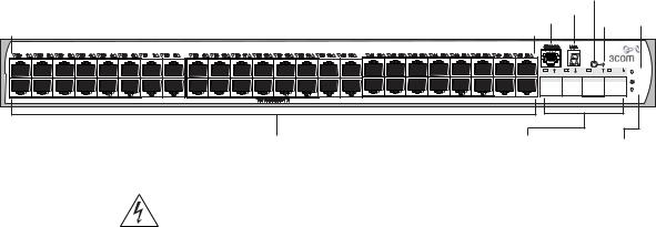
Figure 3 Switch 4200G 48-Port—front view
|
|
|
Unit Status |
|
||||
|
|
|
|
Display |
|
|||
|
|
|
|
|
|
|
Mode |
|
|
|
|
|
|
|
|
|
|
|
Console Port |
|
|
|
|
Switch |
|
|
Port Status LEDs |
|
|
|
|
|
Mode |
Power |
|
|
|
|
|
|
LED |
LED |
||
|
|
|
|
|
|
|
|
|
Speed:Green = 100Mbps, Yellow = 10Mbps |
Duplex:Green = Full Duplex, Yellow = Half Duplex |
Power:Green = Deliverng Power. Yellow=Fault, Flashing Green=Over Budget |
|
Mode |
|
|
Green=Speed |
|
|||
|
|
|
|
Yellow=Duplex |
|
|
|
49 |
50 |
51/49 |
52/50 |
|
|
|
|
|
PWR |
|
|
|
|
|
MOD1 |
|
|
|
|
|
MOD1 |
10/100/1000BASE-T Ports |
Gigabit SFP |
10Gbps |
|
Ports |
Interface Slot |
|
|
LEDs |
WARNING: RJ-45 Ports. These are shielded RJ-45 data sockets. They cannot be used as standard traditional telephone sockets, or to connect the unit to a traditional PBX or public telephone network. Only connect RJ-45 data connectors, network telephony systems, or network telephones to these sockets.
Either shielded or unshielded data cables with shielded or unshielded jacks can be connected to these data sockets.
10/100/1000BASE-T The Switch 4200G has 12, 24 or 48 auto-negotiating
Ports 10BASE-T/100BASE-TX ports configured as Auto MDIX (crossover). When auto-negotiation is enabled these ports automatically operate in MDI or MDIX mode as needed. These ports provide 10/100/1000 Mbps full-duplex connections to other Gigabit Ethernet devices. Full-duplex allows packets to be transmitted and received simultaneously which effectively doubles the potential throughput of a link.
These ports require either straight-through or cross-over Category 5 cables with RJ-45 connectors at each end. The maximum UTP cable length is 100 m (328 ft) over Category 5 cable.
The 10/100/1000BASE-T ports will auto-negotiate the appropriate speed.

Switch 4200G—Front View Detail 17
1000BASE-X SFP Ports SFP (Small Form Factor Pluggable) ports support fiber Gigabit Ethernet long-wave (LX), long-haul (LH70) and copper (T) SFP Transceivers in any combination. This offers you the flexibility of using SFP transceivers to provide connectivity between the Switch and remote 1000 Mbps workgroups or to create a high capacity aggregated link backbone connection.
The default state for these ports is auto-negotiation enabled, where the speed, duplex and flow control modes are negotiated. As the speed and duplex modes are fixed by the media type, only the flow control is negotiated with the link partner. Alternatively, auto-negotiation can be disabled (except 1000BASE-T which auto-negotiation is mandatory) and the flow control setting can be manually configured.
Console Port The console port allows you to connect a terminal and perform remote or local out-of-band management. As the console port on the Switch is an RJ-45 port, you will need to connect an RJ-45 to DB9 converter cable to a standard null modem cable in order to connect a terminal.
Unit Status Display The Status Display is a seven segment display visible on the front of the Switch. The Status Display indicates switch status conditions such as the unit number, POST test ID, and software upgrade information. In the unlikely event of a hardware fault occurring, the Status Display may be used to help diagnose the problem. For information on using the Status Display for problem solving, see “Solving Problems Indicated by LEDs” on page 54.
Table 4 Status Display
Display |
Mode LED Color |
Description |
|
|
|
|
|
Digit (1–9) |
Mode LED flashing green |
POST (power-on startup tests) running. |
|
|
|
|
|
Digit (0–8) |
Mode LED flashing red |
POST failure. Digit indicates ID of failed test. |
|
|
|
|
|
|
|
0 |
POST test OK |
|
|
|
|
|
|
1 |
CPU error |
|
|
|
|
|
|
2 |
Switch chip error |
|
|
|
|
|
|
3 |
RAM error |
|
|
|
|
|
|
4 |
Flash error |
|
|
|
|
|
|
5 |
Port error |
|
|
|
|
|
|
6 |
PHY error |
|
|
|
|
|
|
7 |
Packet memory error |
|
|
|
|
|
|
8 |
CPLD error |

18 CHAPTER 1: INTRODUCING THE SWITCH 4200G FAMILY
Table 4 Status Display (continued)
Display |
Mode LED Color |
Description |
|
|
|
Rotating bar segment |
Mode LED flashing green |
Software download in progress. |
|
|
|
Flashing “F” |
Mode LED steady red |
Fan failure detected. |
|
|
|
Flashing “t” |
Mode LED flashing red |
Switch is too hot; temperature is critical. |
|
|
|
“C” |
Mode LED green or yellow |
Switch is clustered Commander unit. |
|
|
|
“c” |
Mode LED green or yellow |
Switch is clustered Candidate unit. |
|
|
|
“S” |
Mode LED green or yellow |
Switch is clustered Slave unit. |
|
|
|
“1” |
Mode LED green or yellow |
Switch is un-clustered. |
|
|
|
LEDs Table 5 lists LEDs visible on the front of the Switch, and how to read their status. For information on using the LEDs for problem solving, see “Solving Problems Indicated by LEDs” on page 54.
Table 5 LED Behavior
LED |
Color |
Indicates |
|
|
|
PWR LED |
|
|
|
Green |
The Switch is powered-up and operating normally. |
|
Green flashing |
Self Test (POST) or Software Download is in progress. |
|
Yellow flashing |
One or more ports have failed POST. |
|
Red |
The Switch has failed its Power On Self Test. |
|
Off |
The Switch is not receiving power or there is a fault with the |
|
|
Power Supply Unit. |
Mode LED |
|
|
Speed |
Green |
10/100 Port Speed and Activity, Gigabit SFP Status and |
|
|
Activity, or Stack Status and Activity. |
Duplex Yellow |
10/100 Duplex and Activity, Gigabit SFP Duplex and |
|
|
|
Activity, or Stack Activity. |
10/100/1000BASE-T Port LEDs |
||
Speed |
Green |
A high speed (1000 Mbps) link is present, blinking off for |
|
|
every packet received or transmitted. |
|
Yellow |
A low speed link is present, blinking off for every packet |
|
|
received or transmitted. |
|
Yellow Flashing |
The port has failed POST. |
|
Off |
No link is present. |
Switch 4200G — Rear View Detail 19
Table 5 LED Behavior (continued)
LED |
Color |
Indicates |
|
|
|
Duplex Green |
Full duplex, blinking off for every packet received or |
|
|
|
transmitted. |
|
Yellow |
Half duplex, blinking off for every packet received or |
|
|
transmitted. |
|
Yellow flashing |
The port has failed POST. |
|
Off |
No link is present. |
1000BASE-X Port SFP Port LEDs |
||
Speed |
Green |
A high speed (1000 Mbps) link is present. |
|
Yellow Flashing |
Port failed POST. |
|
Off |
No link is present. |
Duplex Green |
Full duplex packets are being transmitted/received on the |
|
|
|
port. |
|
Yellow |
Half duplex packets are being transmitted/received on the |
|
|
port. |
|
Yellow flashing |
Port failed POST. |
|
Off |
No link is present. |
|
|
|
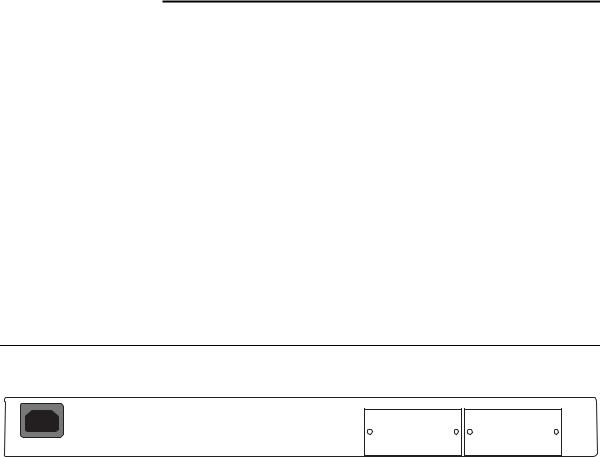
Switch 4200G — Figure 4 Switch 4200G—rear view
Rear View Detail
MOD 1 |
MOD 2 |
|
|
|
|
|
|
|
|
|
|
|
|
|
|
|
|
|
|
|
|
|
|
|
|
|
|
|
|
|
|
|
|
|
|
|
|
|
|
|
|
|
|
|
|
|
|
|
|
|
|
|
|
|
|
|
|
AC Power Input |
10Gbps Interface |
10Gbps Interface |
|||||
|
|
|
|
Slot 1 |
Slot 2 |
||
Power Socket The Switch automatically adjusts its power setting to any supply voltage in the range 100–240 VAC.
10 Gbps Interface The MOD 1 and MOD 2 interface slots accept the 10 Gbps SFP modules.
Slots

20 CHAPTER 1: INTRODUCING THE SWITCH 4200G FAMILY
Default Settings Table 6 shows the default settings for the Switch 4200G Family.
Table 6 Default Settings
Feature |
Switch 4200G |
|
|
Automatic IP Configuration |
Enabled |
Port Status |
Enabled |
Port Speed |
Auto-negotiated |
Duplex Mode |
Auto-negotiated |
Flow Control |
Auto-negotiated |
Broadcast Storm Control |
Enabled |
Virtual LANs (VLANs) |
All ports belong to the untagged Default VLAN |
|
(VLAN 1) with IEEE Std 802.1Q-1998 learning |
|
operational |
Management VLAN |
Fixed as VLAN 1 on 4200G units. Can be any |
|
VLAN for 4200G units. |
Link Aggregation Control |
Disabled per port |
Protocol (LACP) |
|
IP Multicast Filtering |
Filtering enabled |
Rapid Spanning Tree Protocol |
Enabled |
Fast Start |
Enabled on front panel ports |
RMON Alarm |
Enabled |
Traffic Prioritization |
All ports prioritize NBX VoIP traffic (LAN and IP). |
|
All ports set to “best effort” for all other traffic. |
Port Security |
Disabled per port |
Configuration Save and |
Disabled |
Restore |
|
|
|
2 |
INSTALLING THE SWITCH |
This chapter contains the information you need to install and set up the
Switch 4200G. It covers the following topics:
■Package Contents
■Choosing a Suitable Site
■Rack-mounting
■Placing Units On Top of Each Other
■The Power-up Sequence
■SFP Operation
■Choosing the Correct Cables
WARNING: Safety Information. Before installing or removing any components from the Switch 4200G or carrying out any maintenance procedures, you must read the safety information provided in Appendix A of this guide.
AVERTISSEMENT: Consignes de sécurité. Avant d'installer ou d'enlever tout composant du Switch 4200G ou d'entamer une procédure de maintenance, lisez les informations relatives à la sécurité qui se trouvent dans l'Appendice A de ce guide.
VORSICHT: Sicherheitsinformationen. Bevor Sie Komponenten aus dem Switch 4200G entfernen oder dem Switch 4200G hinzufuegen oder Instandhaltungsarbeiten verrichten, lesen Sie die Sicherheitsanweisungen, die in Appendix A (Anhang A) in diesem Handbuch aufgefuehrt sind.
ADVERTENCIA: Información de seguridad. Antes de instalar o extraer cualquier componente del Switch 4200G o de realizar tareas de mantenimiento, debe leer la información de seguridad facilitada en el Apéndice A de esta guía del usuario.
22 CHAPTER 2: INSTALLING THE SWITCH
AVVERTENZA: Informazioni di sicurezza. Prima di installare o rimuovere qualsiasi componente dal Switch 4200G o di eseguire qualsiasi procedura di manutenzione, leggere le informazioni di sicurezza riportate nell'Appendice A della presente guida per l'utente.
OSTRZEŻENIE: Informacje o zabezpieczeniach. Przed instalacją lub usunięciem jakichkolwiek elementów z product lub przeprowadzeniem prac konserwacyjnych należy zapoznać się z informacjami o bezpieczeństwie zawartymi w Załączniku A niniejszego podręcznika.
Package Contents |
■ |
Switch unit |
|
■ CD-ROM (includes documentation related to your Switch) |
|
|
■ Getting Started Guide (this guide) |
|
|
■ |
Release Notes |
|
■ |
Unit Information Labels |
|
■ |
Warranty Information |
|
■ |
Power Cord |
|
■ Console Cable (RJ-45) |
|
|
■ 2 x Mounting brackets |
|
|
■ |
4 x Screws |
|
■ 4 x Rubber feet |
|
|
|
|
Choosing a Suitable |
The Switch is suited for use either free standing on a desktop, or |
|
Site |
mounted in a standard 19-inch equipment rack (for example, in a wiring |
|
|
closet or equipment room). A rack-mounting kit containing two |
|
|
mounting brackets is supplied with the Switch. |
|
CAUTION: Ensure that the ventilation holes are not obstructed.
When deciding where to position the Switch, ensure that:
■Cabling is located away from:
■sources of electrical noise such as radios, transmitters and broadband amplifiers.
■power lines and fluorescent lighting fixtures
■The Switch is accessible and cables can be connected easily.

Rack-mounting 23
■ Water or moisture cannot enter the case of the Switch.
■ Air flow is not restricted around the Switch or through the vents in the side of the Switch. 3Com recommends that you provide a minimum of 25mm (1in.) clearance.
■ Air temperature around the Switch does not exceed 40 °C (104 °F).
If the Switch is installed in a 19-inch rack or closed assembly its local air temperature may be greater than room ambient temperature.
■ The air is as free from dust as possible.
■ The unit is installed in a clean, air conditioned environment.
■ No more than four Switch units are placed on top of one another, if the units are free-standing.
|
■ The Switch is situated away from sources of conductive (electrical) |
|
dust, for example laser printers. |
|
■ The AC supply used by the Switch is separate to that used by units |
|
that generate high levels of AC noise, for example air conditioning |
|
units and laser printers. |
|
|
Rack-mounting |
The Switch 4200G is 1 rack unit (1U) high and will fit in most standard |
|
19-inch racks. |
|
CAUTION: Disconnect all cables from the Switch before continuing. |
|
Remove all self adhesive pads from the underside of the Switch if they |
|
have been fitted. |
|
To rack-mount your Switch: |
|
1 Place the Switch the right way up on a hard flat surface, with the front |
|
facing towards you. |
|
2 Locate a mounting bracket over the mounting holes on one side of the |
|
front of the Switch, as shown in Figure 5. |
You can also rack mount your Switch using the mounting holes at the rear of the Switch.
24 CHAPTER 2: INSTALLING THE SWITCH
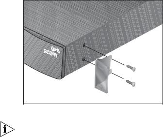
Figure 5 Fitting a Bracket for Rack-Mounting
3Insert the two screws and tighten with a suitable screwdriver.
You must use the screws supplied with the mounting brackets. Damage caused to the unit by using incorrect screws invalidates your warranty.
4Repeat step 2 and step 3 for the other side of the Switch.
5Insert the Switch into the 19-inch rack and secure with suitable screws (not provided). Ensure that ventilation holes are not obstructed.
6Connect network cabling.
7Finally place a unit information label on the unit in an easily accessible position. The unit information label shows the following:
■3Com product name of the Switch
■3Com 3C number of the Switch
■Unique MAC address (Ethernet address) of the Switch
■Serial number of the Switch
You may need this information if you contact 3Com Technical Support.

Placing Units On Top of Each Other 25
Placing Units On If the Switch units are free-standing, up to four units can be placed one Top of Each Other on top of the other. If you are mixing a variety of 3Com equipment, the smaller units must be positioned at the top.
If you are placing Switch units one on top of the other, you must use the self-adhesive rubber feet supplied. Apply the feet to the underside of each Switch, sticking one in the marked area at each corner. Place the Switch units on top of each other, ensuring that the feet of the upper unit sit fully on the lower unit.
The Power-up |
The following sections describe how to get your Switch 4200G |
Sequence |
powered-up and ready for operation. |
Powering-up the Use the following sequence of steps to power-up the Switch.
Switch 4200G
1Plug the power cord into the power socket at the rear of the Switch.
2Plug the other end of the power cord into your power outlet.
The Switch powers-up and runs through its Power On Self Test (POST), which takes approximately one minute.
Checking for Correct During the Power On Self Test, all ports on the Switch are disabled and Operation of LEDs the LEDs light. The PWR LED will flash green during the POST.
When the POST has completed, check the PWR LED to make sure that your Switch is operating correctly. Table 7 shows possible colors for the LED.
Table 7 PWR LED Colors
Color |
State |
|
|
Green |
The Switch is powered-up and operating normally. |
Red |
The Switch has failed its Power On Self Test (POST). |
Yellow flashing |
Some ports have failed POST* |
Off |
The Switch is not receiving power. |
*In this event you can still use the Switch using the remaining ports that have passed the POST.
26 CHAPTER 2: INSTALLING THE SWITCH
|
If there is evidence of a problem, see “Solving Problems Indicated by |
|
LEDs” on page 54 for a list of suggested solutions. |
|
CAUTION: The Switch has no ON/OFF switch; the only method of |
|
connecting or disconnecting mains power is by connecting or |
|
disconnecting the power cord. |
|
|
SFP Operation |
The following section describes how to insert an SFP transceiver into an |
|
SFP port. |
|
SFP transceivers are hot-insertable and hot-swappable. You can remove |
|
them from and insert them into any SFP port without having to power |
|
down the Switch. |
Approved SFP The following list of approved Gigabit Ethernet SFP transceivers is correct Transceivers at the time of publication.
■3CSFP92 SFP (1000BASE-LX)
■3CSFP97 SFP (1000BASE-LH70)
■3CSFP93 SFP (1000BASE-T)
To access the latest list of approved SFP transceivers for the Switch on the 3Com Corporation World Wide Web site, enter this URL into your internet browser:
http://www.3com.com
Inserting an SFP To be recognized as valid, the SFP transceiver must have the following Transceiver characteristics:
■1000BASE-LX SFP transceiver
Use this transceiver to connect Gigabit Ethernet SFP ports on the Switch directly to a single-mode fiber-optic cable or to multimode fiber using a conditioned launch cable.
■1000BASE-LH70 SFP transceiver
Use this transceiver to connect Gigabit Ethernet SFP ports on the Switch directly to a single-mode fiber-optic cable.

SFP Operation 27
■1000BASE-T SFP transceiver
This transceiver uses Category 5 copper cabling with RJ-45 connectors and supports segment lengths of up to 100 m (328 ft).
If the SFP transceiver is faulty, it will not operate within the Switch. See
“Solving Hardware Problems” on page 55.
3Com recommends that you only use SFPs supplied by 3Com. If the SFP transceiver is invalid it will not be recognized by the Switch.
Use the following sequence of steps to activate the SFP ports:
1The SFP transceiver is keyed and there is only one way in which it can be installed correctly. It is not necessary to power-down your Switch.
2Hold the transceiver so that the connector is toward you and the product label is visible. Ensure the wire release lever is closed (in the upright position).
3Gently slide the transceiver into the SFP port until it clicks. If the transceiver does not click into place, remove it, turn it over and re-insert.
4Remove the plastic protective cover if fitted.
Figure 6 Inserting an SFP Transceiver
Product label
Suitable port on host Switch
5Use and appropriate cable to connect the transceiver to a suitable device.
6Check the LEDs on the front of the Switch to ensure that it is operating correctly. Refer to “LEDs” on page 18 for more information.

28 CHAPTER 2: INSTALLING THE SWITCH
Removing an SFP |
If you wish to remove the transceiver (it is not necessary to power-down |
Transceiver |
your Switch): |
1Disconnect the cable from the transceiver.
2Move the wire release lever downwards until it is pointing toward you.
3Pull the wire release lever toward you to release the catch mechanism; the transceiver will then easily slide out.
Choosing the |
All of the ports on the Switch are Auto-MDIX, that is they have a |
Correct Cables |
cross-over capability. These ports can automatically detect whether to |
|
operate in MDI or MDIX mode. Therefore you can make a connection to |
|
one of the ports with a straight-through (MDI) or a cross-over cable |
|
(MDIX). |
|
The Auto-MDIX feature only operates when auto-negotiation is enabled. |
|
If auto-negotiation is disabled, all the Switch ports are configured as |
|
MDIX (cross-over). If you want to make a connection to another MDIX |
|
port, you need a cross-over cable. Many ports on workstations and |
|
servers are configured as MDI (straight-through). If you want to make a |
|
connection to an MDI port, you need to use a standard straight-through |
|
cable. See Table 8. |
|
3Com recommends that you use at least Category 5 twisted pair |
|
cable—the maximum segment length for this type of cable is 100 m (328 |
|
ft.). |
Table 8 Cables required to connect the Switch to other devices if auto-negotiation is disabled
Cross-over Cable |
Straight-through Cable |
Switch to Switch (MDIX to MDIX)
Switch to Hub (MDIX to MDIX)
Switch to PC (NIC) (MDIX to MDI)

Choosing the Correct Cables |
29 |
CAUTION: If you want to install the Switch using a Category 5E or Category 6 cable, 3Com recommends that you briefly connect the cable to a grounded port before connecting network equipment. If you do not, the cable’s Electrostatic Discharge (ESD) may damage the Switch's port.
You can create a grounded port by connecting all wires at one end of a UTP cable to an earth ground point, and the other end to a female RJ-45 connector located, for example, on a Switch rack or patch panel. The RJ-45 connector is now a grounded port.
3Com recommends that you use Category 5 twisted pair cable—the maximum segment length for this type of cable is 100 m (328 ft).
Choosing the Correct All of the ports on the front of the Switch 4200G 28-Port are Cables for the 100BASE-FX MT-RJ multi-mode ports. The MT-RJ port is a small form
Switch 4200G factor fiber-optic port with the transmit and receive fibers in the same cable. Unlike many fiber-optic systems, only one MT-RJ cable is needed to connect two MT-RJ ports together.
To connect a front panel port to another 100BASE-FX MT-RJ multi-mode port, or to a patch panel, a single MT-RJ multi-mode pinless jumper cable is required. Since standard MT-RJ cables are cross-over cables, no Auto-MDIX sensing is required. The maximum cable length is 2 kilometers (1.24 miles).
CAUTION: Do not connect pinned MT-RJ connectors into any port on the Switch 4200G as this may damage the unit. The ports have locator pins fitted and are designed for standard (pinless) connectors.
To connect a front panel port to a 100BASE-FX single mode port, or to a port that does not have an MT-RJ connector, an adaptor will be required. It is not possible to connect a front panel port to a 1000BASE-FX port.
30 CHAPTER 2: INSTALLING THE SWITCH
Loading...