


3CBLSG16
Table of contents
 Loading...
3Com® Baseline Switch 2916-SFP Plus
and Baseline Switch 2924-SFP Plus
User Guide
3CBLSG16 / 3CBLSG24
www.3Com.com
Part Number 10016143 Rev. AA
Published May 2007

3Com Corporation
350 Campus Drive
Marlborough,
MA 01752-3064
Copyright © 2007, 3Com Corporation. All rights reserved. No part of this documentation may be reproduced
in any form or by any means or used to make any derivative work (such as translation, transformation, or
adaptation) without written permission from 3Com Corporation.
3Com Corporation reserves the right to revise this documentation and to make changes in content from time
to time without obligation on the part of 3Com Corporation to provide notification of such revision or change.
3Com Corporation provides this documentation without warranty, term, or condition of any kind, either
implied or expressed, including, but not limited to, the implied warranties, terms or conditions of
merchantability, satisfactory quality, and fitness for a particular purpose. 3Com may make improvements or
changes in the product(s) and/or the program(s) described in this documentation at any time.
If there is any software on removable media described in this documentation, it is furnished under a license
agreement included with the product as a separate document, in the hard copy documentation, or on the
removable media in a directory file named LICENSE.TXT or !LICENSE.TXT. If you are unable to locate a copy,
please contact 3Com and a copy will be provided to you.
UNITED STATES GOVERNMENT LEGEND
If you are a United States government agency, then this documentation and the software described herein are
provided to you subject to the following:
All technical data and computer software are commercial in nature and developed solely at private expense.
Software is delivered as “Commercial Computer Software” as defined in DFARS 252.227-7014 (June 1995) or
as a “commercial item” as defined in FAR 2.101(a) and as such is provided with only such rights as are
provided in 3Com’s standard commercial license for the Software. Technical data is provided with limited
rights only as provided in DFAR 252.227-7015 (Nov 1995) or FAR 52.227-14 (June 1987), whichever is
applicable. You agree not to remove or deface any portion of any legend provided on any licensed program or
documentation contained in, or delivered to you in conjunction with, this User Guide.
Unless otherwise indicated, 3Com registered trademarks are registered in the United States and may or may not
be registered in other countries.
3Com and the 3Com logo are registered trademarks of 3Com Corporation.
Intel and Pentium are registered trademarks of Intel Corporation. Microsoft, MS-DOS, Windows, and Windows
NT are registered trademarks of Microsoft Corporation. Novell and NetWare are registered trademarks of
Novell, Inc. UNIX is a registered trademark in the United States and other countries, licensed exclusively
through X/Open Company, Ltd.
IEEE and 802 are registered trademarks of the Institute of Electrical and Electronics Engineers, Inc.
All other company and product names may be trademarks of the respective companies with which they are
associated.
ENVIRONMENTAL STATEMENT
It is the policy of 3Com Corporation to be environmentally friendly in all operations. To uphold our policy, we
are committed to:
Establishing environmental performance standards that comply with national legislation and regulations.
Conserving energy, materials and natural resources in all operations.
Reducing the waste generated by all operations. Ensuring that all waste conforms to recognized
environmental standards. Maximizing the recyclable and reusable content of all products.
Ensuring that all products can be recycled, reused and disposed of safely.
Ensuring that all products are labelled according to recognized environmental standards.
Improving our environmental record on a continual basis.
End of Life Statement
3Com processes allow for the recovery, reclamation and safe disposal of all end-of-life electronic components.
Regulated Materials Statement
3Com products do not contain any hazardous or ozone-depleting material.
Environmental Statement about the Documentation
The documentation for this product is printed on paper that comes from sustainable, managed forests; it is
fully biodegradable and recyclable, and is completely chlorine-free. The varnish is environmentally friendly, and
the inks are vegetable-based with a low heavy-metal content.

ABOUT THIS GUIDE
This guide provides information about the Web user interface for the
3Com® Baseline Switch 2916-SFP Plus and Baseline Switch 2924-SFP
Plus. The Web interface is a network management system that allows you
to configure, monitor, and troubleshoot your switch from a remote web
browser. The Web interface web pages are easy-to-use and
easy-to-navigate.
User Guide Overview
This section provides an overview to the User Guide. The User Guide
provides the following sections:
■ Getting Started — Provides introductory information about the
Switch 2916 and 2924 and how they can be used in your network. It
covers summaries of hardware and software features.
■ Using the 3Com Web Interface — Provides information for using
the Web interface including adding, editing, and deleting device
configuration information.
■ Viewing Basic Settings — provides information for viewing and
configuring essential information required for setting up and
maintaining device settings.
■ Managing Device Security — Provides information for configuring
both system and network security, including traffic control, ACLs, and
device access methods.
■ General System Information — Provides information for
configuring general system information including the user-defined
system name, the user-defined system location, and the system
contact person.
■ Configuring Ports — Provides information for configuring port
settings.

4 ABOUT THIS GUIDE
■ Aggregating Ports — Provides information for configuring Link
Aggregation which optimizes port usage by linking a group of ports
together to form a single LAG.
■ Configuring VLANs — Provides information for configuring VLANs.
VLANs are logical subgroups with a Local Area Network (LAN) which
combine user stations and network devices into a single virtual LAN
segment, regardless of the physical LAN segment to which they are
attached.
■ Configuring IP and MAC Address Information — Provides
information for configuring IP addresses, DHCP and ARP.
■ Configuring IGMP Snooping — Provides information for
configuring IGMP Snooping.
■ Configuring Spanning Tree — Provides information for configuring
Classic and Rapid Spanning Tree.
■ Configuring SNMP — Provides information for configuring the
Simple Network Management Protocol (SNMP) which provides a
method for managing network devices.
■ Configuring Quality of Service — Provides information defining
Quality of Service, including DSCP and CoS mapping, policies, and
configuring Trust mode.
■ Managing System Files — Provides information for defining file
maintenance.
■ Managing System Logs — Provides information for viewing system
logs, and configuring device log servers.
■ Viewing Statistics — Provides information for viewing RMON and
interface statistics.
■ Managing Device Diagnostics — Provides information for
managing device diagnostics.
Intended Audience 5
Intended Audience This guide is intended for network administrators familiar with IT
concepts and terminology.
If release notes are shipped with your product and the information there
differs from the information in this guide, follow the instructions in the
release notes.
Most user guides and release notes are available in Adobe Acrobat
Reader Portable Document Format (PDF) or HTML on the 3Com Web site:
■ http://www.3Com.com
Conventions Table 1 lists conventions that are used throughout this guide.
Tab le 1 Notice Icons
Icon Notice Type Description
Information
note
Information that describes important features or
instructions.
Related Documentation
Caution Information that alerts you to potential loss of data
or potential damage to an application, system, or
device.
Warning Information that alerts you to potential personal
injury.
In addition to this guide, other documentation available for the 3Com
Baseline Switch 2916-SFP Plus/2924-SFP Plus include the following:
■ Safety and Support Information: Provides installation, set-up, and
regulatory compliance information.

CONTENTS
ABOUT THIS GUIDE
User Guide Overview ................................................................................. 3
Intended Audience..................................................................................... 5
Conventions .............................................................................................. 5
Related Documentation ............................................................................. 5
GETTING STARTED
1
About the Switch 2916 and 2924............................................................ 12
Front Panel Detail..................................................................................... 13
LED Status Indicators................................................................................ 14
System Specifications ............................................................................... 15
Installing the Switch................................................................................. 16
Setting Up for Management .................................................................... 17
Methods of Managing a Switch ............................................................... 17
Switch Setup Overview ............................................................................ 18
Using the Command Line Interface (CLI) .................................................. 21
Setting Up Web Interface Management ................................................... 25
Setting Up SNMP Management V1 or V2 ................................................. 26
Default Users and Passwords.................................................................... 27
Upgrading Software using the CLI............................................................ 27
USING THE 3COM WEB INTERFACE
2
Starting the 3Com Web Interface............................................................. 28
Understanding the 3Com Web Interface .................................................. 30
Using Screen and Table Options ............................................................... 33
Saving the Configuration ......................................................................... 37
Resetting the Device ................................................................................ 38
Restoring Factory Defaults........................................................................ 39
Logging Off the Device ............................................................................ 40

VIEWING BASIC SETTINGS
3
Viewing Device Settings ...........................................................................41
Viewing Color Keys ..................................................................................43
MANAGING DEVICE SECURITY
4
Configuring System Access.......................................................................45
Defining RADIUS Clients ...........................................................................50
Defining Port-Based Authentication (802.1X)............................................52
Defining Access Control Lists ....................................................................57
Enabling Broadcast Storm.........................................................................78
GENERAL SYSTEM INFORMATION
5
Viewing System Description......................................................................80
Configuring System Name Information .....................................................82
Configuring System Time .........................................................................83
CONFIGURING PORTS
6
Viewing Port Settings ...............................................................................85
Defining Port Settings...............................................................................88
Viewing Port Details .................................................................................90
AGGREGATING PORTS
7
Viewing Link Aggregation ........................................................................93
Configuring Link Aggregation ..................................................................93
Modifying Link Aggregation .....................................................................95
Removing Link Aggregation......................................................................96
Viewing LACP ..........................................................................................97
Modifying LACP .......................................................................................98
CONFIGURING VLANS
8
Viewing VLAN Details.............................................................................102
Viewing VLAN Port Details......................................................................103
Creating VLANs......................................................................................104

Modifying VLAN Settings ....................................................................... 105
Modifying Port VLAN Settings ................................................................ 107
Removing VLANs ................................................................................... 108
CONFIGURING IP AND MAC ADDRESS INFORMATION
9
Defining IP Addressing ........................................................................... 109
Configuring ARP Settings....................................................................... 110
Configuring Address Tables.................................................................... 114
10
11
12
13
CONFIGURING IGMP SNOOPING
Introduction........................................................................................... 123
Defining IGMP Snooping........................................................................ 124
CONFIGURING SPANNING TREE
Viewing Spanning Tree .......................................................................... 127
Defining Spanning Tree.......................................................................... 130
Modifying Spanning Tree ....................................................................... 133
CONFIGURING SNMP
Defining SNMP Communities ................................................................. 136
Removing SNMP Communities............................................................... 138
Defining SNMP Traps ............................................................................. 139
Removing SNMP Traps ........................................................................... 140
CONFIGURING QUALITY OF SERVICE
Viewing CoS Settings............................................................................. 143
Defining CoS ......................................................................................... 144
Viewing CoS to Queue .......................................................................... 145
Defining CoS to Queue .......................................................................... 145
Viewing DSCP to Queue ........................................................................ 147
Configuring DSCP Queue....................................................................... 148
Configuring Trust Settings...................................................................... 149
Viewing Bandwidth Settings .................................................................. 150

Defining Bandwidth Settings ..................................................................151
Defining Voice VLAN ..............................................................................153
14
15
16
17
A
MANAGING SYSTEM FILES
Backing Up System Files .........................................................................163
Restoring Files ........................................................................................164
Upgrade the Firmware Image .................................................................165
Activating Image Files.............................................................................166
MANAGING SYSTEM LOGS
Viewing Logs..........................................................................................168
Configuring Logging ..............................................................................169
VIEWING STATISTICS
Viewing Port Statistics ............................................................................172
MANAGING DEVICE DIAGNOSTICS
Configuring Port Mirroring .....................................................................175
Viewing Cable Diagnostics .....................................................................178
3COM NETWORK MANAGEMENT
3Com Network Supervisor......................................................................181
3Com Network Director .........................................................................182
3Com Network Access Manager ............................................................182
3Com Enterprise Management Suite ......................................................183
Integration Kit with HP OpenView Network Node Manager ....................183
DEVICE SPECIFICATIONS AND FEATURES
B
Related Standards ..................................................................................184
Environmental ........................................................................................184
Physical ..................................................................................................184
Electrical.................................................................................................185
Switch Features ......................................................................................185

PIN-OUTS
C
Console Cable ....................................................................................... 189
Null Modem Cable................................................................................. 190
PC-AT Serial Cable ................................................................................. 190
Modem Cable........................................................................................ 190
Ethernet Port RJ-45 Pin Assignments...................................................... 191
TROUBLESHOOTING
D
Problem Management ........................................................................... 192
Troubleshooting Solutions...................................................................... 192
3COM CLI REFERENCE GUIDE
E
Getting Started with the Command Line Interface ................................. 195
CLI Commands ...................................................................................... 196
GLOSSARY
F
............................................................................................................. 206
OBTAINING SUPPORT FOR YOUR 3COM PRODUCTS
G
Register Your Product to Gain Service Benefits ....................................... 212
Solve Problems Online............................................................................ 212
Purchase Extended Warranty and Professional Services........................... 212
Access Software Downloads .................................................................. 213
Contact Us............................................................................................. 213
REGULATORY NOTICES

1
GETTING STARTED
This chapter contains introductory information about the 3Com® Baseline
Switch 2916-SFP Plus and the Baseline Switch 2924-SFP Plus and how
they can be used in your network. It covers summaries of hardware and
software features and also the following topics:
■ About the Switch 2916 and 2924
■ Front Panel Detail
■ LED Status Indicators
■ System Specifications
■ Installing the Switch
■ Setting Up for Management
■ Methods of Managing a Switch
■ Switch Setup Overview
■ Using the Command Line Interface (CLI)
■ Setting Up Web Interface Management
■ Setting Up SNMP Management V1 or V2
■ Default Users and Passwords
■ Upgrading Software using the CLI

12 CHAPTER 1: GETTING STARTED
About the Switch 2916 and 2924
Summary of
Hardware Features
The Switch 2916 and Switch 2924 are Gigabit Ethernet switching
products that deliver flexible three-speed performance (10/100/1000) and
advanced voice-optimized features such as auto-QoS and auto-voice
VLAN. This makes the switches ideal for medium businesses and small
enterprises seeking to build a secure converged network.
The Switch 2916 and 2924 includes the following models:
■ Baseline Switch 2916-SFP Plus 16-Port
■ Baseline Switch 2924-SFP Plus 24-Port
The Switch 2916 and 2924 feature the following advantages:
■ Full Gigabit speed access ports
■ Jumbo frames
■ Port security
■ Link aggregation control protocol (LACP)
■ Up to 256 VLANs
■ Access control lists (ACLs)
■ Port-based mirroring
Table 1 summarizes the hardware features supported by the Switch 2916
and 2924.
Tab le 1 Hardware Features
Feature Switch 2916 and 2924
Addresses Up to 8,000 supported
Auto-negotiation Supported on all ports
Forwarding Modes Store and Forward
Duplex Modes Half and full duplex on all front panel ports
Auto MDI/MDIX Supported on all ports. If fiber SFP transceivers are used,
Auto MDIX is not supported.
Flow Control In full duplex operation all ports are supported.
The Switch 2916 and 2924 ports are capable of
receiving, but not sending pause frames.
Traffic Prioritization Supported (using the IEEE Std 802.ID, 1998 Edition):
Eight traffic queues per port
Front Panel Detail 13
Tab le 1 Hardware Features (continued)
Feature Switch 2916 and 2924
Ethernet, Fast Ethernet,
Auto-negotiating 10/100/1000BASE-T ports
and Gigabit Ethernet Ports
SFP Ethernet Ports Supports fiber Gigabit Ethernet long-wave (LX), and
fiber Gigabit Ethernet short-wave (SX) transceivers in
any combination.
Mounting 19-inch rack or standalone mounting
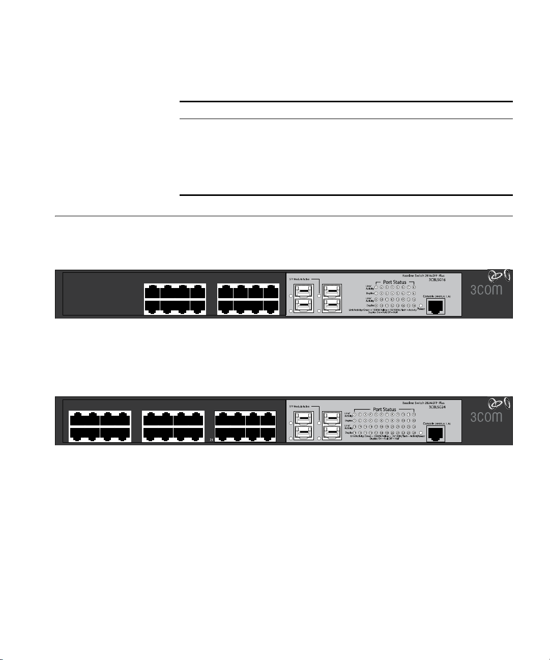
Front Panel Detail Figure 1 shows the front panel of the Switch 2916-SFP Plus 16-Port unit.
Figure 1 Switch 2916 SFP 16-Port—front panel
1
9
4
5
13
12
8
14
16
15
16
16
Figure 2 shows the front panel of the Switch 2924-SFP Plus 24-Port unit.
Figure 2 Switch 2924 SFP Plus 24-Port—front panel
1
13
4
5
16
17
9
8
20
12
22
24
21
24
23

14 CHAPTER 1: GETTING STARTED
LED Status Indicators
The 2916-SFP Plus 16-Port and 24-Port Ethernet switches provide LED
indicators on the front panel for your convenience to monitor the switch.
Table 2 describes the meanings of the LEDs.
Tab le 2 Description on the LEDs of the Switch 2916 and 2924
LED Label Status Description
Power Power Green The switch starts normally. The LED flashes
when the system is performing power-on self
test (POST).
Yellow The system has failed the POST.
OFF The switch is powered off.
10/100/1000
BASE-T
Ethernet port
status
Duplex mode Duplex Yellow The port is in full duplex mode.
1000Base SFP
port status
Link/
Activity
SFP
Module
Active
Green The port works at the rate of 1000 Mbps; the
LED flashes quickly when the port is sending
or receiving data.
Yellow The port works at the rate of 10/100 Mbps;
the LED flashes quickly when the port is
sending or receiving data.
OFF The port is not connected.
OFF The port is not connected, or is in half duplex
mode.
Green The SFP module is inserted.
OFF The SFP module is not inserted or is not
recognized.

System Specifications 15
System Specifications
Table 3 contains the system specifications of the Switch 2916 and 2924
series switches.
Tab le 3 System specifications of the Switch 2916 and 2924 series switches
Specification
Physical dimensions
(H×W×D)
Weight 2.0 kg (4.4 lb)
Console port One Console port
Gigabit Ethernet ports on
the front panel
AC Input voltage Rated voltage range: 100–240 VAC, 50/60 Hz
Power consumption
(full load)
Operating temperature 0 to 40 °C (32 to 113 °F)
Relative humidity 10 to 90% noncondensing
Switch 2916-SFP Plus
16-Port 3CBLSG16
44×440×173 mm (1.73 17.3 6.81 in.)
16 × 10/100/100 Mbps
Ethernet ports
Four Gigabit SFP Combo
ports
58 W 84 W
Switch 2924-SFP Plus
24-Port 3CBLSG24
24 × 10/100/100 Mbps
Ethernet ports
Four Gigabit SFP Combo
ports
Additional specifications can be found in Appendix B “Device
Specifications and Features”.
16 CHAPTER 1: GETTING STARTED
Installing the Switch
This section contains information that you need to install and set up your
3Com switch.
WARNING: Safety Information. Before you install or remove any
components from the Switch or carry out any maintenance procedures,
you must read the 3Com Switch Family Safety and Regulatory
Information document enclosed.
AVERTISSEMENT: Consignes de securite. Avant d'installer ou d'enlever
tout composant de Switch ou d'entamer une procedure de maintenance,
lisez les informations relatives a la securite qui se trouvent dans 3Com
Switch Family Safety and Regulatory Information.
VORSICHT: Sicherheitsinformationen. Bevor Sie Komponenten aus
dem Switch entfernen oder den Switch hinzufugen oder
Instandhaltungsarbeiten verrichten, lesen Sie die 3Com Switch Family
Safety and Regulatory Information.
ADVERTENCIA: Informacion de seguridad. Antes de instalar o extraer
cualquier componente del Switch o de realizar tareas de mantenimiento,
debe leer la informacion de seguridad facilitada en el 3Com Switch Family
Safety and Regulatory Information.
AVVERTENZA: Informazioni di sicurezza. Prima di installare o
rimuovere qualsiasi componente dal Switch o di eseguire qualsiasi
procedura di manutenzione, leggere le informazioni di sicurezza riportate
3Com Switch Family Safety and Regulatory Information.
OSTRZEŻENIE: Informacje o zabezpieczeniach. Przed instalacją
lub usunięciem jakichkolwiek elementów z product lub
przeprowadzeniem prac konserwacyjnych należy zapoznać się z
informacjami o bezpieczeństwie zawartymi w 3Com Switch Family
Safety and Regulatory Information.
CAUTION: Opening the switch or tampering with the warranty sticker
can void your warranty.

Setting Up for Management 17
Setting Up for Management
Methods of Managing a Switch
To make full use of the features offered by your switch, and to change
and monitor the way it works, you have to access the management
software that resides on the switch. This is known as managing the
switch. Managing the switch can help you to improve the efficiency of
the switch and therefore the overall performance of your network.
This section explains the initial set up of the switch and the different
methods of accessing the management software to manage a switch. It
covers the following topics:
■ Methods of Managing a Switch
■ Switch Setup Overview
■ Manually set the IP Address using the Console Port
■ Viewing IP Information using the Console Port
■ Setting Up Web Interface Management
■ Setting Up SNMP Management V1 or V2
■ Default Users and Passwords
To manage your switch you can use one of the following methods:
■ Web Interface Management
Web Interface
Management
■ SNMP Management
In addition, you can use the Command Line Interface through the
Console port for basic operations of the switch including setting and
viewing the IP address, configuring user accounts, upgrading switch
firmware, and more. Refer to “3Com CLI Reference Guide” on page 195.
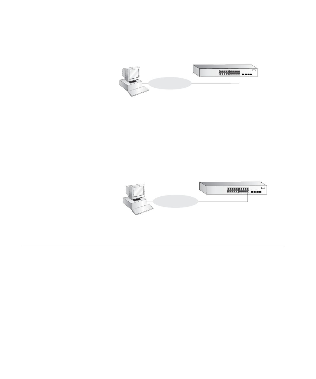
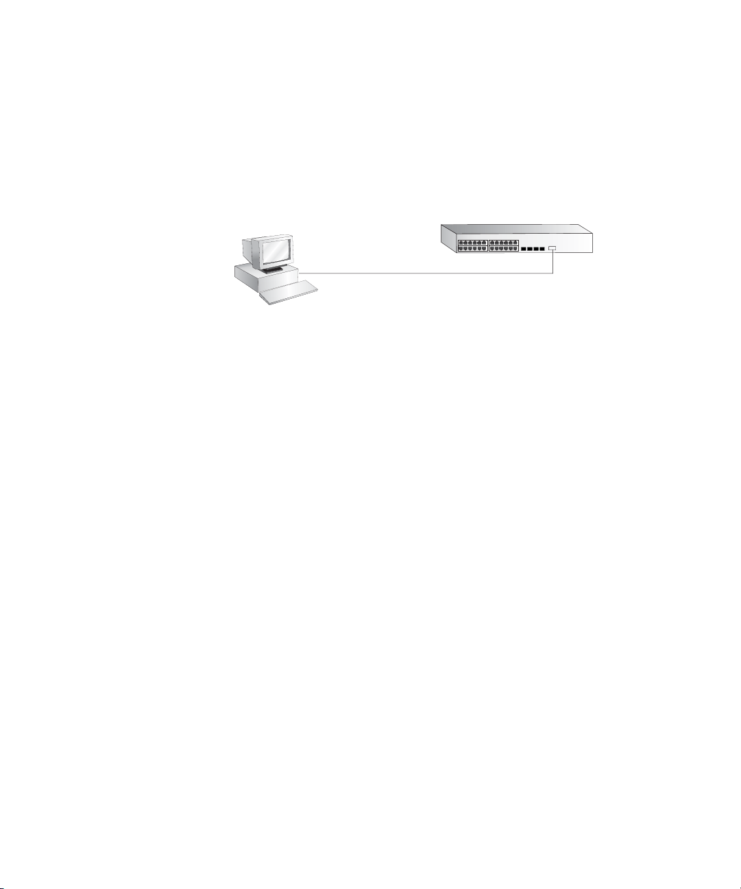
Each switch has an internal set of web pages that allow you to manage
the switch using a Web browser remotely over an IP network (see
Figure 3).
18 CHAPTER 1: GETTING STARTED
Figure 3 Web Interface Management over the Network
Workstation
Connect over Network
via web browser
Switch
Refer to “Setting Up Web Interface Management” on page 25.
SNMP Management You can manage a switch using any network management workstation
running the Simple Network Management Protocol (SNMP) as shown in
Figure 4. For example, you can use the 3Com Network Director software,
available from the 3Com website.
Figure 4 SNMP Management over the Network
Switch Setup Overview
SNMP Network Management
Workstation
Connect over Network
using SNMP
Switch
Refer to “Setting Up SNMP Management V1 or V2” on page 26.
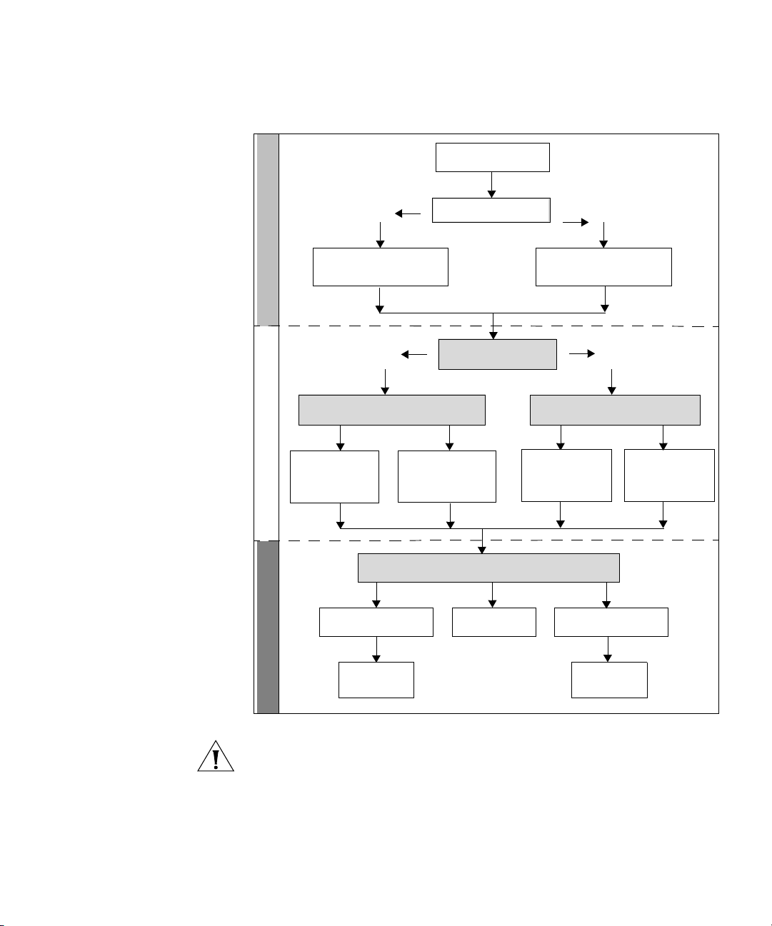
This section gives an overview of what you need to do to get your switch
set up and ready for management when it is in its default state. The
whole setup process is summarized in Figure 5. Detailed procedural steps
are contained in the sections that follow. In brief, you need to:
■ Configure IP information manually for your switch or view the
automatically configured IP information
■ Prepare for your chosen method of management
Switch Setup Overview 19
Figure 5 Initial Switch Setup and Management Flow Diagram
Power Up the Switch.
Plug and Play Setup
Connect to the
console port and use
the Command Line
Initial IP Information Setup
Yes
IP Information is automatically
configured using DHCP
See page 20
Yes
How do you want to connect to the Switch?
Connect to a front panel
port and use the Web
Interface.
Interface.
See page 21
Command Line Interface
(basic setup only)
See page 25
How do you want to manage your Switch? See page 17
Is a DHCP server present?
Do you want to manually
configure the IP information?
Refer to the label on
the rear of the switch
which details the
default IP address.
SNMP
See page 26
No
The switch uses its default IP
information
See page 20
No
How do you want to view the automatically
configured IP information?
Connect to the
console port and use
the Command Line
Interface.
See page 23
Web Interface
Feature Management
Connect using the
console port.
See page 21
Connect over the
network.
See page 26
CAUTION: To protect your switch from unauthorized access, you must
change the default password as soon as possible, even if you do not
intend to actively manage your switch. For more information on default
users and changing default passwords, see “Default Users and
Passwords” on page 27.

20 CHAPTER 1: GETTING STARTED
IP Configuration The switch’s IP configuration is determined automatically using DHCP, or
manually using values you assign.
Automatic IP Configuration using DHCP
By default the switch tries to configure its IP Information without
requesting user intervention. It tries to obtain an IP address from a DHCP
server on the network.
Default IP Address If no DHCP server is detected, the switch will use
its default IP information. The default IP address is 169.254.x.y, where x
and y are the last two bytes of its MAC address.
Note: The switch’s default IP address is listed on a label located on the
rear of the switch.
If you use automatic IP configuration it is important that the IP address of
the switch is static, otherwise the DHCP server can change the switch’s IP
addresses and it will be difficult to manage. Most DHCP servers allow
static IP addresses to be configured so that you know what IP address will
be allocated to the switch. Refer to the documentation that accompanies
your DHCP server.
You should use the automatic IP configuration method if:
■ your network uses DHCP to allocate IP information, or
■ flexibility is needed. If the switch is deployed onto a different subnet, it
will automatically reconfigure itself with an appropriate IP address,
instead of you having to manually reconfigure the switch.
If you use the automatic IP configuration method, you need to discover
the automatically allocated IP information before you can begin
management. Work through the “Viewing IP Information using the
Console Port” on page 23.
Manual IP Configuration
When you configure the IP information manually, the switch remembers
the information that you enter until you change it again.
You should use the Manual IP configuration method if:
■ You do not have a DHCP server on your network, or
■ You want to remove the risk of the IP address ever changing, or
Using the Command Line Interface (CLI) 21
■ Your DHCP server does not allow you to allocate static IP addresses.
(Static IP addresses are necessary to ensure that the switch is always
allocated the same IP information.)
For most installations, 3Com recommends that you configure the switch
IP information manually. This makes management simpler and more
reliable as it is not dependent on a DHCP server, and eliminates the risk of
the IP address changing.
To manually enter IP information for your switch, work through the
“Manually set the IP Address using the Console Port” on page 22.
Using the Command Line Interface (CLI)
Connecting to the
Console Port
You can access the switch through the Console port to manually set the
IP address, or to view the IP address that was assigned automatically (for
example, by a DHCP server).
For more information about the CLI, refer to “3Com CLI Reference Guide”
on page 195.
This section describes how to connect to your switch through the
Console port.
Prerequisites
■ A workstation with terminal emulation software installed, such as
Microsoft Hyperterminal. This software allows you to communicate
with the switch using the console port directly.
■ Documentation supplied with the terminal emulation software.
■ The console cable (RJ-45) supplied with your switch.
You can find pin-out diagrams for the cable in Appendix C on page 189.
22 CHAPTER 1: GETTING STARTED
Connecting the Workstation to the Switch
1 Connect the workstation to the console port using the console cable as
shown in Figure 6.
Figure 6 Connecting a Workstation to the Switch using the Console Port
To connect the cable:
a Attach the cable’s RJ-45 connector to the Console port of the switch.
b Attach the other end of the cable to the workstation.
2 Open your terminal emulation software and configure the COM port
settings to which you have connected the cable. The settings must be set
to match the default settings for the switch, which are:
■ 38,400 baud (bits per second)
Workstation
(with terminal emulation
software installed)
Console Cable
Switch
Console Port
Connection
Manually set the IP
Address using the
Console Port
■ 8 data bits
■ no parity
■ 1 stop bit
■ no hardware flow control
Refer to the documentation that accompanies the terminal emulation
software for more information.
3 Power up the switch. The Power on Self Test (POST) will be performed.
The Switch 2916 and 2924 takes approximately one minute to boot.
You are now ready to manually set up the switch with IP information
using the command line interface.
■ You need to have the following information:
■ IP address
■ subnet mask
■ default gateway

Using the Command Line Interface (CLI) 23
1 Connect to the switch Console port as described in “Connecting to the
Console Port” page 21.
2 The command line interface login sequence begins as soon as the switch
detects a connection to its console port. When the process completes,
the Login prompt displays.
Viewing IP
Information using the
Console Port
3 At the login prompt, enter
admin as your user name and press Return.
The Password prompt displays.
4 Press Return. If you have logged on correctly, Select menu option#
should be displayed.
5 Enter the IP address and subnet mask for the switch as follows:
ipSetup xxx.xxx.xxx.xxx mmm.mmm.mmm.mmm
and then press Enter.
(Note: xxx.xxx.xxx.xxx is the IP address and mmm.mmm.mmm.mmm is
the subnet mask of the switch.)
6 Enter the logout command to terminate the CLI session.
The initial setup of your switch is now complete and the switch is ready
for you to set up your chosen management method. See “Methods of
Managing a Switch” on page 17.
This section describes how to view the automatically allocated IP
information using the command line interface. The automatic IP
configuration process usually completes within one minute after the
switch is connected to the network and powered up.
1 Connect to the switch Console port as described in “Connecting to the
Console Port” page 21.
The automatic IP configuration process usually completes within one
minute.
2 The command line interface login sequence begins as soon as the switch
detects a connection to its console port.
3 At the login prompt, enter
admin as your user name and press Return.
4 At the password prompt, press Return.If you have logged on correctly,
Select menu option# is displayed.

24 CHAPTER 1: GETTING STARTED
5 Enter Summary to view a summary of allocated IP addresses. The
following is an example of the display from the Summary command.
Select menu option# summary
IP Method: default
IP address: 169.254.99.51
Subnet mask: 255.255.0.0
Runtime version: 00_00_38 (date 01-Apr-2007 time 15:31:29)
Bootcode version: 1.0.0.12 (date 01-Apr-2007 time 17:44:52)
Select menu option#
The initial set up of your switch is now complete and the switch is ready
for you to set up your chosen management method. See “Methods of
Managing a Switch” on page 17.
For more information about the CLI, refer to “3Com CLI Reference Guide”
on page 195.
If you do not intend to use the command line interface using the console
port to manage the switch, you can logout, disconnect the serial cable
and close the terminal emulator software.

Setting Up Web Interface Management 25
Setting Up Web Interface Management
This section describes how you can set up web interface management
over the network.
Prerequisites
■ Ensure you have already set up the switch with IP information as
described in “Methods of Managing a Switch” on page 17.
■ Ensure that the switch is connected to the network using a Category 5
twisted pair Ethernet cable with RJ-45 connectors.
■ A suitable Web browser.
Choosing a Browser
To display the web interface correctly, use one of the following Web
browser and platform combinations:
Tab le 4 Supported Web Browsers and Platforms
Platform
Browser
Internet Explorer 6 Yes Yes Yes
Internet Explorer 7 Yes Yes Yes
Firefox 1.5 Yes Yes Yes
Firefox 2 Yes Yes Yes
Netscape 8 Yes Yes Yes
Windows 2000 Windows XP Windows Vista
For the browser to operate the web interface correctly, JavaScript and
Cascading Style Sheets must be enabled on your browser. These features
are enabled on a browser by default. You will only need to enable them if
you have changed your browser settings.
The switch’s Web interface supports both secure (HTTPS) and non-secure
(HTTP) connections.

26 CHAPTER 1: GETTING STARTED
Web Management
Over the Network
To manage a switch using the web interface over an IP network:
1 Be sure that you know your switch’s IP address. See “IP Configuration”
on page 20, and “Viewing IP Information using the Console Port” on
page 23.
2 Check that your management workstation is on the same subnet as your
switch.
3 Check you can communicate with the switch by entering a ping
command at the DOS or CMD prompt in the following format:
c:\ ping xxx.xxx.xxx.xxx
(where xxx.xxx.xxx.xxx is the IP address of the switch)
If you get an error message, check that your IP information has been
entered correctly and the switch is powered up.
4 Open your web browser and enter the IP address of the switch that you
wish to manage in the URL locator, for example, in the following format:
http://xxx.xxx.xxx.xxx
5 At the login and password prompts, enter admin as your user name and
press Return at the password prompt (or the password of your choice if
you have already modified the default passwords).
The main Web interface page is displayed.
Setting Up SNMP Management V1 or V2
You can use any network management application running the Simple
Network Management Protocol (SNMP) to manage the switch. 3Com
offers a range of network management applications to address networks
of all sizes and complexity. See “3Com Network Management” on
page 181.
Be sure the management workstation is connected to the switch using a
port in VLAN 1 (the Default VLAN). By default, all ports on the switch are
in VLAN 1.
To display and configure SNMP management parameters, refer to
“Configuring SNMP” on page 135.
Default Users and Passwords 27
Default Users and Passwords
Upgrading Software using the CLI
If you intend to manage the switch or to change the default passwords,
you must log in with a valid user name and password. The switch has one
default user name. The default user is listed in Table 5.
Tab le 5 Default Users
User Name
admin (no password) Management — The user can access and change
Default
Password
Access Level
all manageable parameters
Use the admin default user name (no password) to login and carry out
initial switch setup.
This section describes how to upgrade software to your Switch from the
Command Line Interface (CLI).
Note: You can also upgrade the software using the switch Web user
interface. See “Upgrade the Firmware Image” page 165. Bootcode can
only be upgraded using the CLI.
1 To download the runtime application file, enter:
upgrade aaa.aaa.aaa.aaa rrr runtime
where aaa.aaa.aaa.aaa is the IP address of the TFTP server and rrr is the
source runtime filename.
2 To download the bootcode file, enter:
upgrade aaa.aaa.aaa.aaa bbb bootcode
where aaa.aaa.aaa.aaa is the IP address of the TFTP server and bbb is the
source bootcode filename.
The bootcode firmware may not require upgrading for every software
upgrade, therefore there may not be a new bootcode file to download.
3 To set the switch to boot from the new software you have downloaded,
enter the following:
reboot
The following prompt displays:
Are you sure you want to reboot the system (yes, no):
4 Enter yes and press Return. The system reboots the switch.

2
USING THE 3COM WEB INTERFACE
This section provides an introduction to the user interface, and includes
the following topics:
■ Starting the 3Com Web Interface
■ Understanding the 3Com Web Interface
■ Saving the Configuration
■ Resetting the Device
■ Restoring Factory Defaults
■ Logging Off the Device
Starting the 3Com Web Interface
Multi-Session Web
Connections
This section includes the following topics:
■ Multi-Session Web Connections
■ Accessing the 3Com Web Interface
The Multi-Session web connections feature enables 10 users to be
created and access the switch concurrently. Access levels provide read or
read/write permissions to users for configuring the switch. Users and
access levels are described in Configuring System Access Section. Login
information is always handled in the local database. A unique password is
required of each user. Two access levels exist on the 3Com Web Interface:
■ Management access level — Provides the user with read/write
access. There is always one management level user configured for the
switch. The factory default is be username: admin with no Password.
■ Monitor access level — Provides the user with read-only access.

Starting the 3Com Web Interface 29
Accessing the 3Com
Web Interface
This section contains information on starting the 3Com Web interface.
To access the 3Com user interface:
1 Open an Internet browser.
2 Enter the device IP address in the address bar and press Enter. The Enter
Network Password Page opens:
Figure 7 Enter Network Password Page
3 Enter your user name and password. The device default factory settings is
configured with a User Name that is admin and a password that is blank.
Passwords are case sensitive.
4 Click Login. The 3Com Web Interface Home Page opens:
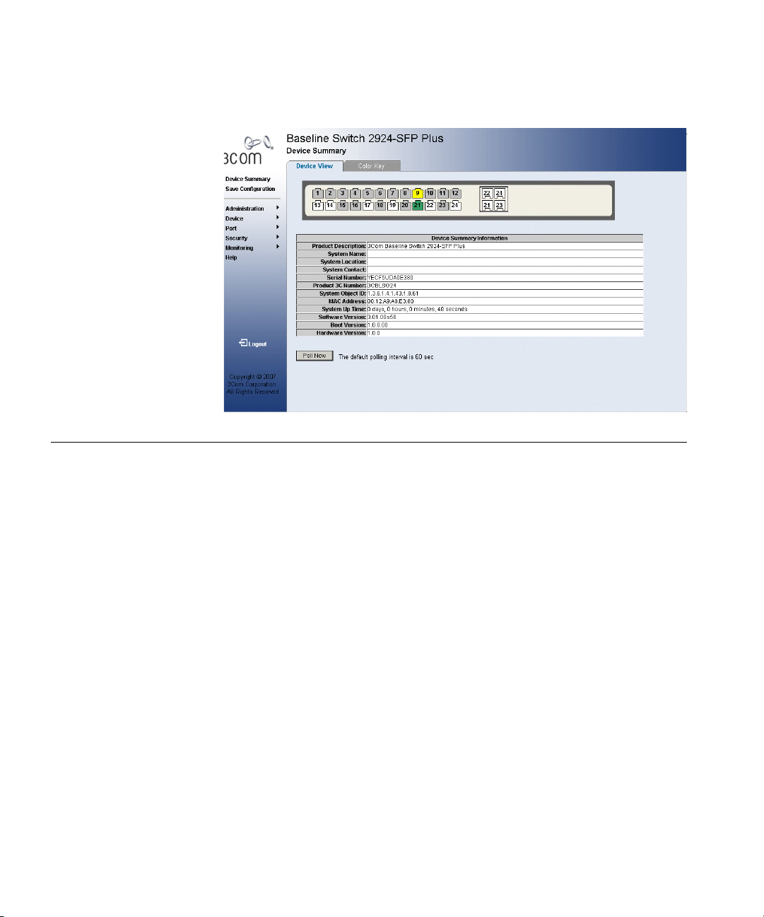
30 CHAPTER 2: USING THE 3COM WEB INTERFACE
Figure 8 3Com Web Interface Home Page
Understanding the 3Com Web Interface
The 3Com Web Interface Home Page contains the following views:
■ Tab V ie w — Provides the device summary configuration located at
the top of the home page.
■ Tree Vie w — Provides easy navigation through the configurable
device features. The main branches expand to display the
sub-features.
■ Port Indicators — Located under the Device View at the top of the
home page, the port indicators provide a visual representation of the
ports on the front panel.
Loading...