


 Loading...
Baseline Switch 2226-SFP Plus
Baseline Switch 2426-PWR Plus
Baseline Switch 2250-SFP Plus
User Guide
3CBLSF26H
3CBLSF26PWRH
3CBLSF50H
Part No.: 10017022
Manual Version: 6W104
www.3com.com
3Com Corporation
350 Campus Drive, Marlborough,
MA, USA 01752 3064
Copyright © 2008-2009, 3Com Corporation. All rights reserved. No part of this documentation may be reproduced in any form or by any means or used to make any derivative work (such as translation, transformation, or adaptation) without written permission from 3Com Corporation.
3Com Corporation reserves the right to revise this documentation and to make changes in content from time to time without obligation on the part of 3Com Corporation to provide notification of such revision or change.
3Com Corporation provides this documentation without warranty, term, or condition of any kind, either implied or expressed, including, but not limited to, the implied warranties, terms or conditions of merchantability, satisfactory quality, and fitness for a particular purpose. 3Com may make improvements or changes in the product(s) and/or the program(s) described in this documentation at any time.
If there is any software on removable media described in this documentation, it is furnished under a license agreement included with the product as a separate document, in the hard copy documentation, or on the removable media in a directory file named LICENSE.TXT or !LICENSE.TXT. If you are unable to locate a copy, please contact 3Com and a copy will be provided to you.
UNITED STATES GOVERNMENT LEGEND
If you are a United States government agency, then this documentation and the software described herein are provided to you subject to the following:
All technical data and computer software are commercial in nature and developed solely at private expense. Software is delivered as “Commercial Computer Software” as defined in DFARS 252.227-7014 (June 1995) or as a “commercial item” as defined in FAR 2.101(a) and as such is provided with only such rights as are provided in 3Com’s standard commercial license for the Software. Technical data is provided with limited rights only as provided in DFAR 252.227-7015 (Nov 1995) or FAR 52.227-14 (June 1987), whichever is applicable. You agree not to remove or deface any portion of any legend provided on any licensed program or documentation contained in, or delivered to you in conjunction with, this User Guide.
Unless otherwise indicated, 3Com registered trademarks are registered in the United States and may or may not be registered in other countries.
3Com and the 3Com logo are registered trademarks of 3Com Corporation.
All other company and product names may be trademarks of the respective companies with which they are associated.
ENVIRONMENTAL STATEMENT
It is the policy of 3Com Corporation to be environmentally-friendly in all operations. To uphold our policy, we are committed to:
Establishing environmental performance standards that comply with national legislation and regulations.
Conserving energy, materials and natural resources in all operations.
Reducing the waste generated by all operations. Ensuring that all waste conforms to recognized environmental standards. Maximizing the recyclable and reusable content of all products.
Ensuring that all products can be recycled, reused and disposed of safely.
Ensuring that all products are labelled according to recognized environmental standards.
Improving our environmental record on a continual basis.
End of Life Statement
3Com processes allow for the recovery, reclamation and safe disposal of all end-of-life electronic components.
Regulated Materials Statement
3Com products do not contain any hazardous or ozone-depleting material.
Environmental Statement about the Documentation
The documentation for this product is printed on paper that comes from sustainable, managed forests; it is fully biodegradable and recyclable, and is completely chlorine-free. The varnish is environmentally-friendly, and the inks are vegetable-based with a low heavy-metal content.
About This Manual
Organization
3Com Baseline Switch User Guide is organized as follows:
|
Chapter |
|
Contents |
|
1 |
Getting Started |
|
This chapter contains introductory information about the |
|
|
installation of the switch and how they can be used in your |
|||
|
|
|
network. |
|
|
|
|
|
|
2 |
Connecting To the Web Interface |
This chapter introduces the setting the menu items and |
||
buttons that are available on the Web interface. |
||||
|
|
|
||
|
|
|
|
|
3 |
Configuring the Switch |
|
This chapter introduces how to configure the switch in detail. |
|
|
|
|
|
|
4 |
Troubleshooting |
|
This chapter lists some issues that you may encounter while |
|
|
installing, using, and managing the switch, with suggested |
|||
|
|
|
courses of corrective action to take. |
|
|
|
|
|
|
5 |
CLI Reference Guide |
|
This chapter describes using the Command Line Interface |
|
|
(CLI) to manage the switch. |
|||
|
|
|
||
|
|
|
|
|
6 |
Obtaining Support for |
Your |
This chapter introduces how to get support for your product. |
|
Product |
|
|||
|
|
|||
|
|
|
|
|
7 |
Safety Information |
|
This chapter describes the important safety information for |
|
|
you product. |
|||
|
|
|
||
|
|
|
|
|
8 |
Regulatory Notices |
|
This chapter describes the important regulatory notices for |
|
|
you product. |
|||
|
|
|
||
|
|
|
|
|
9 |
Glossary |
|
This chapter lists the main glossaries for the manual. |
|
|
|
|
|
|
Conventions
The manual uses the following conventions:
Command conventions
|
Convention |
|
Description |
|
|
|
Boldface |
|
The keywords of a command line are in Boldface. |
|
|
|
|
|
|
|
|
|
italic |
|
Command arguments are in italic. |
|
|
|
|
|
|
||
[ ] |
|
Items (keywords or arguments) in square brackets [ ] are optional. |
|
||
|
|
|
|
||
|
{ x | y | ... } |
|
Alternative items are grouped in braces and separated by vertical bars. |
||
|
|
One is selected. |
|
|
|
|
|
|
|
|
|
|
|
|
|
|
|
|
[ x | y | ... ] |
|
Optional alternative items are grouped in square |
brackets |
and |
|
|
separated by vertical bars. One or none is selected. |
|
|
|
|
|
|
|
|
|
|
|
|
|
||
|
{ x | y | ... } * |
|
Alternative items are grouped in braces and separated by vertical bars. |
||
|
|
A minimum of one or a maximum of all can be selected. |
|
|
|
|
|
|
|
|
|
|
|
|
|
|
|
|
[ x | y | ... ] * |
|
Optional alternative items are grouped in square |
brackets |
and |
|
|
separated by vertical bars. Many or none can be selected. |
|
||
|
|
|
|
||
|
|
|
|
||
|
&<1-n> |
|
The argument(s) before the ampersand (&) sign can be entered 1 to n |
||
|
|
times. |
|
|
|
|
|
|
|
|
|
|
|
|
|
|
|

Convention |
Description |
# |
A line starting with the # sign is comments. |
|
|
GUI conventions
Convention |
Description |
|
Boldface |
Window names, button names, field names, and menu items are in |
|
Boldface. For example, the New User window appears; click OK. |
||
|
||
|
|
|
> |
Multi-level menus are separated by angle brackets. For example, File > |
|
Create > Folder. |
||
|
||
|
|
Symbols
Convention |
Description |
|
|
Means reader be careful. Improper operation may cause data loss or damage to equipment.
Means a complementary description.
Obtaining Documentation
You can access the most up-to-date 3Com product documentation on the World Wide Web at this URL: http://www.3com.com.
Table of Contents
1Getting Started···········································································································································1-1
Introducing the Switch·····························································································································1-1 Overview of the Switch····················································································································1-1 Summary of Hardware Features ·····································································································1-1 Front View Detail ·····························································································································1-2 LED Status Indicators······················································································································1-3 System Specifications ·····················································································································1-4
Installing the Switch ································································································································1-5 Before You Begin ····························································································································1-5 Package Contents ···························································································································1-5 Positioning the Switch ·····················································································································1-5 Rack-Mounting or Free-Standing ····································································································1-6 Supplying Power to the Switch········································································································1-7 Checking for Correct Operation·······································································································1-8 Using SFP Transceivers··················································································································1-8 Performing Spot Checks················································································································1-10
Configuring IP Address ·························································································································1-10 Automatic IP Configuration using DHCP·······················································································1-11 Manual IP Configuration················································································································1-11
2Connecting To the Web Interface ············································································································2-1
Requirements for Accessing the Web Interface ·····················································································2-1 Choosing a Web Browser ·······················································································································2-1 Default User and Password ····················································································································2-2 Logging On to the Web Interface ············································································································2-2 Navigating the Web Interface··················································································································2-2
Menu················································································································································2-2 Buttons ············································································································································2-5
3Configuring the Switch ·····························································································································3-1
Configuring System Access ····················································································································3-1 Defining System Access··················································································································3-1 Modifying System Access ···············································································································3-2 Removing System Access···············································································································3-3 Viewing System Access Settings ····································································································3-3
Configuring IP and MAC Address Information························································································3-4 Defining IP Address·························································································································3-4 Configuring ARP Settings················································································································3-5 Configuring MAC Address Table·····································································································3-7 Configuring Port ····································································································································3-11 Configuring Port Basic Settings·····································································································3-11 Configuring PoE ····························································································································3-14 Viewing Port Statistics···················································································································3-16 Configuring VLAN ·································································································································3-18
i
Creating VLANs·····························································································································3-19 Modifying VLAN·····························································································································3-19 Modifying Port VLAN Settings ·······································································································3-20 Renaming VLANs··························································································································3-21 Removing VLANs ··························································································································3-21 Viewing VLAN Details····················································································································3-22 Viewing VLAN Port Details············································································································3-23
Aggregating Port ···································································································································3-24 Overview········································································································································3-24 LACP ·············································································································································3-24 Link Aggregation Types·················································································································3-24 Configuring Link Aggregation ········································································································3-25 Configuring LACP··························································································································3-28
Configuring STP····································································································································3-29 Configuring IGMP Snooping ·················································································································3-35 Defining IGMP Snooping···············································································································3-35 Configuring ACL····································································································································3-36 Configuring MAC Based ACL········································································································3-36 Configuring IP Based ACL ············································································································3-40 Configuring ACL Binding ···············································································································3-44 Configuring QoS····································································································································3-46 Configuring CoS ····························································································································3-46 Configuring Queue Algorithm ········································································································3-47 Configuring CoS to Queue ············································································································3-48 Configuring DSCP to Queue ·········································································································3-49 Configuring Trust Mode·················································································································3-51 Configuring Bandwidth Settings ····································································································3-51 Configuring Voice VLAN················································································································3-53 Configuring SNMP ································································································································3-58 Defining SNMP Communities········································································································3-58 Removing SNMP Communities·····································································································3-59 Defining SNMP Traps····················································································································3-59 Removing SNMP Traps·················································································································3-60 Configuring LLDP··································································································································3-61 LLDP Overview······························································································································3-61 Configuring Global LLDP Parameters···························································································3-61 Configuring Port-Level LLDP Parameters·····················································································3-62 Viewing LLDP Information·············································································································3-64 Managing Switch Security·····················································································································3-66 Defining Port-Based Authentication (802.1X) ···············································································3-66 Defining Radius Client···················································································································3-69 Configuring LDB ····························································································································3-70 Configuring Broadcast Storm Control····························································································3-73 Managing System Information ··············································································································3-74 Viewing Basic Settings ··················································································································3-75 Configuring System Name ············································································································3-76 Configuring System Time ··············································································································3-77
ii
Save Configuration························································································································3-78 Resetting the Switch······················································································································3-79 Managing System Files·························································································································3-79 Managing System Logs ························································································································3-82 Configuring Logging ······················································································································3-83 Viewing Logs ·································································································································3-84 Managing Switch Diagnostics ···············································································································3-85 Configuring Port Mirroring ·············································································································3-85 Configuring Cable Diagnostics ······································································································3-86
4Troubleshooting ········································································································································4-1
Resetting to Factory Defaults··················································································································4-1 Forgotten Password································································································································4-1 Reset the switch ······························································································································4-1 Configure a new user ······················································································································4-2 Forgotten Static IP Address ····················································································································4-2 Solving LED Issues·································································································································4-2
5CLI Reference Guide ·································································································································5-1
Getting Started with the Command Line Interface··················································································5-1 Prerequisites····································································································································5-1 Logging on to the CLI ······················································································································5-1 CLI Features ···········································································································································5-2 Online Help······································································································································5-2 Command History····························································································································5-3 Error Messages ·······························································································································5-3 Command Edit·································································································································5-4
CLI Configuration ····································································································································5-4 display ip··········································································································································5-4 display management-vlan ···············································································································5-5 display version·································································································································5-6 ip address ········································································································································5-6 ip address dhcp-alloc·······················································································································5-6 ip gateway ·······································································································································5-7 localuser ··········································································································································5-7 management-vlan····························································································································5-8 management-vlan port·····················································································································5-8 ping··················································································································································5-9 quit·················································································································································5-10 reboot·············································································································································5-10 restore ···········································································································································5-11 save ···············································································································································5-11 tftp update······································································································································5-12
6Obtaining Support for Your Product ·······································································································6-1
Register Your Product·····························································································································6-1 Purchase Value-Added Services ············································································································6-1 Access Software Downloads ··················································································································6-1 Telephone Technical Support and Repair ······························································································6-1
iii
Contact Us ··············································································································································6-2
7Safety Information ·····································································································································7-1
Important Safety Information···················································································································7-1
8Regulatory Notices····································································································································8-1
FCC Statement ·······································································································································8-1 Information to the User····························································································································8-1 ICES Statement ······································································································································8-1 CE Statement (Europe)···························································································································8-1 VCCI Statement ······································································································································8-2
9Glossary ·····················································································································································9-1
iv

1 Getting Started
zThis manual applies to the Baseline Switch 2250-SFP Plus, Baseline Switch 2226-SFP Plus, and Baseline Switch 2426-PWR Plus, which are hereinafter referred to as the switch.
zThis manual takes the Web interfaces of the Baseline Switch 2426-PWR Plus as an example.
This chapter contains introductory information about the installation of the switch and how they can be used in your network. It covers the following topics:
z
z
z
Introducing the Switch
Installing the Switch
Configuring IP Address
Introducing the Switch
This chapter covers summary information about the hardware and the following topics:
z
z
z
z
z
Overview of the Switch
Summary of Hardware Features
Front View Detail
LED Status Indicators
System Specifications
Overview of the Switch
zThe Baseline Switch 2226-SFP Plus is a versatile, easy-to-use configurable switch.
zThe Baseline Switch 2426-PWR Plus is a versatile, easy-to-use configurable Power-over-Ethernet (PoE) Switch.
zThe Baseline Switch 2250-SFP Plus is a versatile, easy-to-use configurable switch.
Each Switch is ideal for users who want the high-speed performance of 10/100 switching with the added functionality of Gigabit copper and fiber links, but do not need sophisticated management capabilities. The Switch is shipped ready for use. No configuration is necessary.
Summary of Hardware Features
Table 1-1 Summarizes the hardware features supported by the Switch.
Table 1-1 Hardware Features
Feature |
Description |
Addresses |
Up to 8192 supported. |
|
|
Auto-negotiation |
Supported on all ports. |
|
|
|
1-1 |
|
Feature |
|
Description |
|
Forwarding Modes |
|
Store and Forward. |
|
|
|
|
|
Duplex Modes |
Half and full duplex on all front panel ports. |
|
|
|
|
|
|
Auto MDI/MDIX |
|
Supported on all ports. If fiber SFP transceivers are used, |
|
|
Auto MDIX is not supported. |
|
|
|
|
|
|
|
|
|
|
Flow Control |
In full duplex operation all ports are supported. |
|
|
|
|
|
|
Traffic Prioritization |
|
Four traffic queues per port. |
|
|
|
|
|
|
|
10/100 Mbps ports. |
|
Ethernet Ports |
|
Each port automatically determines the speed and duplex |
|
|
mode of the connected equipment and provides a suitable |
|
|
|
|
switched connection. The 10/100 Mbps ports can operate in |
|
|
|
either half-duplex or full-duplex mode. |
|
|
|
|
|
|
|
The 2 Gigabit combo ports support fiber Gigabit Ethernet |
|
|
|
short-wave (SX) and long-wave (LX) SFP transceivers in |
|
|
|
any combination. This offers you the flexibility of using SFP |
|
Gigabit Combo Ports |
|
transceivers to provide connectivity between the Switch and |
|
|
a 1000 Mbps core network. |
|
|
|
|
|
|
|
|
When an SFP port is in operation, the corresponding |
|
|
|
1000BASE-T port is disabled. The 1000 Mbps connections |
|
|
|
can only operate in full duplex mode. |
|
|
|
|
|
Mounting |
|
19-inch rack or standalone mounting. |
|
|
|
|
|
Fanless design (supported by |
|
|
|
Baseline Switch 2226-SFP Plus and |
|
Silent operation whether used in a rack or desktop situation. |
|
Baseline Switch 2250-SFP Plus) |
|
|
|
|
|
|
|
|
|
Each RJ-45 port supports the IEEE 802.3af PoE standard. |
|
|
|
Any 802.3af compliant device attached to a port can directly |
|
PoE (Only supported by Baseline |
|
draw power from the switch over the Ethernet cable without |
|
|
requiring its own separate power source. This capability |
|
|
Switch 2426-PWR Plus) |
|
|
|
|
gives network administrators centralized power control for |
|
|
|
|
|
|
|
|
devices such as IP phones and wireless access points, |
|
|
|
which translates into greater network availability. |
|
|
|
|
Front View Detail
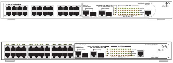
Figure 1-1 shows the front panel of the Baseline Switch 2226-SFP Plus 26-Port unit.
Figure 1-1 Baseline Switch 2226-SFP Plus 26-Port—front panel.
Figure 1-2 Shows the front panel of the Baseline Switch 2426-PWR Plus 26-Port unit.
Figure 1-2 Baseline Switch 2426-PWR Plus 26-Port—front panel.
Figure 1-3 shows the front panel of the Baseline Switch 2250-SFP Plus 50-Port unit.
1-2
Figure 1-3 Baseline Switch 2250-SFP Plus 50-Port—front panel.
LED Status Indicators
The Switch provides LED indicators on the front panel for your convenience to monitor the switch. Table 1-2 describes the meanings of the LEDs.
Table 1-2 Description on the LEDs of the Switch
|
|
LED |
|
Status |
|
Description |
|
|
|
|
|
|
|
|
The switch starts normally. The LED flashes |
|
|
|
|
|
Green |
|
when the system is performing Power-On |
|
|
Power |
|
|
|
Self-Test (POST). |
|
|
|
|
|
|
|
||
|
|
|
Yellow |
|
The system has failed the POST. |
||
|
|
|
|
|
|
||
|
|
|
|
|
|
|
|
|
|
|
|
|
OFF |
The switch is powered off. |
|
|
|
|
|
|
|
|
|
|
|
Link/Activity |
|
|
|
|
The port works at the rate of 100 Mbps; the |
|
|
|
|
Green |
|
LED flashes quickly when the port is sending |
|
|
|
|
|
|
|
|
or receiving data. |
|
|
|
|
|
|
|
|
|
|
|
|
|
|
|
The port works at the rate of 10 Mbps; the |
|
|
|
|
|
Yellow |
|
LED flashes quickly when the port is sending |
|
|
|
|
|
|
|
or receiving data. |
|
|
|
|
|
|
|
|
|
|
|
|
|
|
|
The link has not been established, either |
|
|
|
10/100BASE-T |
|
|
|
nothing is connected to the port, or there is a |
|
|
|
port |
|
|
|
problem: |
|
|
|
|
|
|
|
z Check that the attached device is powered |
|
|
|
|
|
OFF |
|
on. |
|
|
|
|
|
|
z Check that the cable is the correct type |
|
|
|
|
|
|
|
|
and is not faulty. |
|
|
|
|
|
|
|
If these checks do not identify the cause of the |
|
|
|
|
|
|
|
problem, it may be that the unit or the device |
|
|
|
|
|
|
|
connected to the port is faulty. Contact your |
|
|
|
|
|
|
|
supplier for further advice. |
|
|
|
|
|
|
|
|
|
|
|
10/100/1000BAS |
|
|
|
The port works at the rate of 1000 Mbps; the |
|
|
|
|
Green |
|
LED flashes quickly when the port is sending |
|
|
|
|
E-T port |
|
|
||
|
|
|
|
|
|
or receiving data. |
|
|
|
|
|
|
|
|
|
|
|
|
|
|
|
|
|
|
|
|
|
|
|
|
The port works at the rate of 10/100 Mbps; the |
|
|
|
|
|
Yellow |
|
LED flashes quickly when the port is sending |
|
|
|
|
|
|
|
or receiving data. |
|
|
|
|
|
|
|
|
1-3
|
|
|
LED |
|
Status |
|
Description |
|
|
|
|
|
|
|
|
|
The link has not been established, either |
|
|
|
|
|
|
|
|
nothing is connected to the port, or there is a |
|
|
|
|
|
|
|
|
problem: |
|
|
|
|
|
|
|
|
z Check that the attached device is powered |
|
|
|
|
|
|
|
|
on. |
|
|
|
|
|
|
|
|
z Check that the cable or fiber is the correct |
|
|
|
|
|
|
OFF |
|
type and is not faulty. |
|
|
|
|
|
|
|
z For fiber connections, ensure that the |
|
|
|
|
|
|
|
|
|
|
|
|
|
|
|
|
|
|
receive (RX) and transmit (TX) cable |
|
|
|
|
|
|
|
|
connectors are not swapped. |
|
|
|
|
|
|
|
|
If these checks do not identify the cause of the |
|
|
|
|
|
|
|
|
problem, it may be that the unit or the device |
|
|
|
|
|
|
|
|
connected to the port is faulty. Contact your |
|
|
|
|
|
|
|
|
supplier for further advice. |
|
|
|
|
|
|
|
|
|
|
|
|
|
10/100/1000BAS |
|
Yellow |
The port is in full duplex mode. |
|
|
|
Duplex |
|
|
|
|
|
|
|
|
|
|
|
|
The port is not connected, or is in half duplex |
||
|
|
|
E-T port |
|
OFF |
|
||
|
|
|
|
|
|
|||
|
|
|
|
|
|
|
mode. |
|
|
|
|
|
|
|
|
|
|
|
|
|
|
|
|
|
|
|
|
|
|
|
|
|
Green |
The SFP module is inserted. |
|
|
|
Module Active |
SFP port |
|
|
|
|
|
|
|
|
OFF |
The SFP module is not inserted or is not |
||||
|
|
|
|
|
|
|||
|
|
|
|
|
|
recognized. |
||
|
|
|
|
|
|
|
||
|
|
|
|
|
|
|
|
|
|
|
|
|
|
|
Green |
|
The port is supplying power to the device |
|
|
PoE Power (Only supported by |
|
|
connected to it. |
|||
|
|
|
|
|
||||
|
|
|
|
|
|
|||
|
|
Baseline Switch 2426-PWR Plus) |
|
OFF |
The port is not supply power to the device |
|||
|
|
|
|
|
|
|||
|
|
|
|
|
|
connected to it or not connected. |
||
|
|
|
|
|
|
|
||
|
|
|
|
|
|
|
|
|
System Specifications
Table 1-3 contains the system specifications of the Switch.
Table 1-3 System specifications of the Switch.
Specification |
2226-SFP |
2426-PWR |
2250-SFP |
|
Physical dimensions |
44 mm×440 mm×170 |
44 mm×440 mm×238 |
44 mm×440 mm×238 |
|
(H×W×D) |
mm |
mm |
mm |
|
|
|
|
|
|
Weight |
1.6 kg |
3.2 kg |
2.9 kg |
|
|
|
|
|
|
Console port |
1 |
1 |
1 |
|
|
|
|
|
|
|
|
24 (Each port can |
|
|
Ethernet port |
24 |
provide a power |
48 |
|
|
|
supply of 25 W) |
|
|
|
|
|
|
|
Gigabit Combo port |
2 |
2 |
2 |
|
|
|
|
|
|
|
Rated voltage range: |
Rated voltage range: |
Rated voltage range: |
|
AC Input voltage |
100–240V AC, 50/60 |
100–240V AC, 50/60 |
100–240V AC, 50/60 |
|
|
Hz |
Hz |
Hz |
|
|
|
|
|
|
Power consumption (full |
17 W |
205 W |
26 W |
|
load) |
||||
|
|
|
||
|
|
|
|
|
Operating temperature |
0°C to 40°C (32°F to 113°F) |
|
||
|
|
|
||
Storage temperature |
–10°C to +70°C (14°F to 158°F) |
|
||
|
|
|
|
|
|
1-4 |
|
|
|
|
Specification |
|
2226-SFP |
2426-PWR |
2250-SFP |
|
Operating humidity |
|
20% to 85% |
|
|
|
(noncondensing) |
|
|
|
|
|
|
|
|
|
|
|
|
|
|
|
|
|
Storage humidity |
|
10% to 90% |
|
|
|
(noncondensing) |
|
|
|
|
|
|
|
|
|
|
|
|
|
|
|
|
Installing the Switch
This section contains information that you need to install and set up the switch. It covers the following topics:
z
z
z
z
z
z
z
z
Before You Begin
Package Contents Positioning the Switch
Rack-Mounting or Free-Standing Supplying Power to the Switch Checking for Correct Operation Using SFP Transceivers Performing Spot Checks
Before You Begin
Before installing or removing any components from the switch or carrying out any maintenance procedures, read the safety information provided in Safety Information of this guide.
Package Contents
The Baseline Switch packaging contains the following for all units:
z
z
z
z
z
z
One product sealed in a plastic bag One CD
One Safety and Regulatory Information manual One warranty card
One Mounting Kit
One DB-9 to RJ-45 cable
Positioning the Switch
The switch is suitable for use in an office environment where it can be free-standing or mounted in a standard 19-inch equipment rack.
Alternatively, the switch can be rack-mounted in a wiring closet or equipment room. A mounting kit, containing two mounting brackets and four screws, is supplied with the switch.
When deciding where to position the switch, ensure that:
zIt is accessible and cables can be connected easily.
zCabling is away from sources of electrical noise. These include lift shafts, microwave ovens, and air conditioning units. Electromagnetic fields can interfere with the signals on copper cabling and introduce errors, therefore slowing down your network.
zWater or moisture cannot enter the case of the unit.
1-5
zAir flow around the unit and through the vents on the side of the case is not restricted (3Com recommends that you provide a minimum of 25 mm (1 in.) clearance).
zThe air is as free from dust as possible.
zTemperature operating limits are not likely to be exceeded. It is recommended that the unit is installed in a clean, air conditioned environment.
It is always good practice to wear an anti-static wrist strap when installing network equipment, connected to a ground point. If one is not available, try to keep in contact with a grounded rack and avoid touching the unit's ports and connectors, if possible. Static discharge can cause reliability problems in your equipment.
Rack-Mounting or Free-Standing
The unit can be mounted in a 19-inch equipment rack using the mounting kit or it can be free standing. Do not place objects on top of the unit or stack.
If installing the switch in a free-standing stack of different size Baseline or Super stack 3 units, the smaller units must be installed above the larger ones. Do not have a free-standing stack of more than six units.
Using the Mounting Kit
The switch is supplied with two mounting brackets and four screws. These are used for rack mounting the unit. When mounting the unit, you should take note of the guidelines given in Positioning the Switch.
The switch is 1U (1.7 inches) high and will fit in a standard 19-inch rack.
Disconnect all cables from the unit before continuing. Remove the self-adhesive pads from the underside of unit, if already fitted.
To rack-mount the switch:
1)Place the unit the right way up on a hard, flat surface with the front facing towards you.
2)Locate a mounting bracket over the mounting holes on one side of the unit.
3)Insert the two screws supplied in the mounting kit and fully tighten with a suitable screwdriver.
1-6
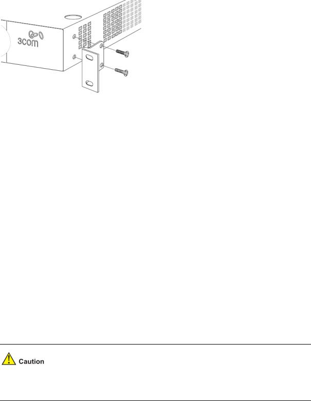
Figure 1-4 Rack Mounting the Unit
4)Repeat steps 2 and 3 for the other side of the unit.
5)Insert the unit into the 19-inch rack and secure with suitable screws (not provided).
6)Reconnect the cables.
Placing Units On Top of Each Other
If the switch units are free-standing, up to six units can be placed one on top of the other. If you are mixing a variety of Baseline and Super Stack units, the smaller units must be positioned at the top.
If you are placing switch units one on top of the other, you must use the self-adhesive rubber pads supplied. Apply the pads to the underside of each switch, sticking one in the marked area at each corner.
Place the switch units on top of each other, ensuring that the pads of the upper unit line up with the recesses of the lower unit.
Supplying Power to the Switch
Power problems can be the cause of serious failures and downtime in your network. Ensure that the power input to your system is clean and free from sags and surges to avoid unforeseen network outages. 3Com recommends that you install power conditioning, especially in areas prone to blackout, power dips and electrical storms.
The unit is intended to be grounded. Ensure it is connected to earth ground during normal use. Installing proper grounding helps to avoid damage from lightning and power surges.
Before powering on the switch, verify that the network cables and the power cable are securely connected.
To power on the switch:
1)Plug the power cord into the power socket on the rear panel of the switch.
2)Plug the other end of the power cord into a power outlet.
1-7

Checking for Correct Operation
After you power on the switch, it automatically performs a power-on self-test (POST). During POST, the Power LED on the front panel of the switch flashes green.
When POST is complete, the Power LED turns green. If the Power LED turns yellow after POST, it means that POST failed and the switch has entered fail-safe mode.
The following summarizes the possible colors for the Power LED after POST.
Table 1-4 Summarizes the possible colors for the Power LED after POST
Status |
Meaning |
|
Green |
The unit is powered on and ready for use. |
|
|
|
|
Yellow |
Power-on self-test or loop back test failed. The switch is in fail-safe mode. |
|
This can happen if a port or ports fail when the switch was powered on. |
||
|
||
|
|
|
|
The unit is not receiving power. |
|
Off |
z Verify that the power cord is connected correctly, and then try powering on |
|
the switch again |
||
|
||
|
z If the switch still does not operate, contact your 3Com network supplier |
|
|
|
If POST fails, try the following:
zPower off the switch, and then power it on again. Check the Power LED and see if POST was successfully completed.
zReset the switch. See Resetting to Factory Defaults.
Resetting the switch to its factory default erases all your settings. You will need to reconfigure the switch after you reset it.
If these do not resolve the issue:
zCheck the 3Com Knowledgebase for a solution. To visit the 3Com Knowledgebase Web site, start your Web browser, and then enter http://knowledgebase.3com.com.
zContact your 3Com network supplier for assistance.
Using SFP Transceivers
The following sections describe how to insert an SFP transceiver into an SFP slot.
SFP transceivers are hot-insertable and hot-swappable. You can remove them from and insert them into any SFP port without having to power down the switch.
1-8

Approved SFP Transceivers
The following list of approved SFP transceivers is correct at the time of publication:
z
z
3CSFP91 SFP (SX) 3CSFP92 SFP (LX)
To access the latest list of approved SFP transceivers for the switch on the 3Com Web site, enter this URL into your Internet browser: http://www.3com.com
3Com recommends using 3Com SFPs on the switch. If you insert an SFP transceiver that is not supported, the switch will not recognize it.
Inserting an SFP Transceiver
To be recognized as valid, the SFP transceiver must have the following characteristics:
1000BASE-SX or 1000BASE-LX media type:
z1000BASE-SX SFP transceiver
Use this transceiver to connect the switch directly to a multimode fiber-optic cable.
z1000BASE-LX SFP transceiver
Use this transceiver to connect the switch directly to a single mode fiber-optic cable or to multi-mode fiber using a conditioned launch cable.
To activate the SFP port:
1)Hold the transceiver so that the fiber connector is toward you and the product label is visible, as shown in Figure 1-5.Ensure the wire release lever is closed (in the upright position).
Figure 1-5 Inserting an SFP Transceiver
Product label
Wire release lever
Suitable slot on host Switch
2)Gently slide the transceiver into the SFP slot until it clicks into place.
1-9

SFP transceivers are keyed and can be properly inserted only one way. If the transceiver does not click when you insert it, remove it, turn it over, and reinsert it.
3)Remove the plastic protective cover, if fitted.
4)Connect the fiber cable.
5)Attach a male duplex LC connector on the network cable into the duplex LC connector on the transceiver.
6)Connect the other end of the cable to a device fitted with an appropriate Gigabit Ethernet connection.
7)Check the Module Active LEDs on the front of the switch to ensure that the SFP transceiver is operating correctly.
Removing an SFP Transceiver
To remove an SFP transceiver:
1)Disconnect the cable from the transceiver.
2)Move the wire release lever downwards until it is pointing toward you.
3)Pull the wire release lever toward you to release the catch mechanism.
The SFP transceiver should slide out easily.
Performing Spot Checks
At frequent intervals, you should visually check the switch. Regular checks can give you an early warning of a possible failure; any problems can then be attended to when there will be least effect on users.
3Com recommends periodically checking the items listed in Table 1-5.
Table 1-5 Items to Check
|
Item |
|
Operation |
|
|
|
Where possible, check that the cooling fan is operating by listening to the unit. |
|
Cooling fan |
|
The fan is fitted near to the front right hand side of the unit (when viewed from |
|
|
|
the front). |
|
|
|
|
|
Cabling |
|
Check that all external cabling connections are secure and that no cables are |
|
|
pulled taut. |
|
|
|
|
|
|
|
|
|
Configuring IP Address
The switch’s IP configuration is determined automatically using DHCP, or manually using values you assign.
By default, the switch will use its default IP information. The default IP address is 169.254.xxx.xxx. If the MAC address is 08004E000102, the IP address would be 169.254.1.2.
1-10

Automatic IP Configuration using DHCP
When you use the automatic IP configuration method, the switch tries to obtain its IP information without requesting user intervention from a DHCP server on the network.
You should use the automatic IP configuration method if:
zYour network uses DHCP to allocate IP information, or
zFlexibility is needed. If the switch is deployed onto a different subnet, it will automatically reconfigure itself with an appropriate IP address, instead of you having to manually reconfigure the switch.
You can use ip address dhcp-alloc command to define automatic IP configuration method and use display ip command to view the automatically allocated IP Information through the Console Port (see CLI Reference Guide).
Manual IP Configuration
When you configure the IP information manually, the switch remembers the information that you enter until you change it again.
You should use the manual IP configuration method if:
z
z
z
You do not have a DHCP server on your network, or
You want to remove the risk of the IP address ever changing, or Your DHCP server does not allow you to allocate static IP addresses.
For most installations, 3Com recommends that you configure the switch IP information manually. This makes management simpler and more reliable as it is not dependent on a DHCP server, and eliminates the risk of the IP address changing.
You can use ip address command to configure the static IP for your switch through the Console Port (see CLI Reference Guide).
1-11

2 Connecting To the Web Interface
The switch has a built-in Web interface that you can use to set the user password, change the IP address that is assigned to the switch, and configure its advanced settings.
This chapter introduces the setting the menu items and buttons that are available on the Web interface. The following topics are covered:
z
z
z
z
z
Requirements for Accessing the Web Interface Choosing a Web Browser
Default User and Password Logging On to the Web Interface Navigating the Web Interface
Requirements for Accessing the Web Interface
To connect to the Web interface, you need the following:
zEnsure that the switch is connected to the network using a Category 5 twisted pair Ethernet cable with RJ-45 connectors.
zEnsure that you know your switch’s IP address. See Configuring IP Address.
zCheck that your management workstation is on the same subnet as your switch.
zChoose a suitable Web browser.
Choosing a Web Browser
To display the Web interface correctly, use one of the following Web browsers and platform combinations:
Table 2-1 Supported Web Browsers and Platforms
Platform |
|
Windows 2000 |
|
|
Windows XP |
|
|
Windows Vista |
|
Browser |
|
|
|
|
|
|
|||
|
|
|
|
|
|
|
|
|
|
Internet Explorer 6 |
|
Yes |
|
Yes |
|
Yes |
|||
|
|
|
|
|
|
|
|||
Internet Explorer 7 |
|
Yes |
|
Yes |
|
Yes |
|||
|
|
|
|
||||||
Firefox 1.5 |
Yes |
Yes |
Yes |
||||||
|
|
|
|
||||||
Firefox 2 |
Yes |
Yes |
Yes |
||||||
|
|
|
|
|
|
|
|||
Netscape 8 |
|
Yes |
|
Yes |
|
Yes |
|||
|
|
|
|
|
|
|
|
|
|
For the browser to operate the Web interface correctly, JavaScript and Cascading Style Sheets must be enabled on your browser. These features are enabled on a browser by default. You will only need to enable them if you have changed your browser settings.
2-1
Default User and Password
If you intend to manage the switch or to change the default password, you must log in with a valid user name and password. The switch has one default user name. The default user is listed in Table 2-2.
Table 2-2 Default User and Password
|
User Name |
Default Password |
|
|
Access Level |
|
admin |
- |
|
|
Management: The user can access and change all |
|
|
|
manageable parameters |
||
|
|
|
|
|
|
|
|
|
|
|
|
Logging On to the Web Interface
To log on to the Web interface, do the following:
1)Open your Web browser and enter the IP address of the switch that you wish to manage in the URL locator (For example, in the following format: http://xxx.xxx.xxx.xxx). The Login Page appears:
Figure 2-1 Login Page
2)Enter admin as your user name and leave the password field blank.
3)Click Login, The main Web interface page is displayed.
Navigating the Web Interface
The Web interface has been designed to enable you to easily perform advanced configuration tasks and view information about the switch.
Menu
The menu is located on the left side of the Web interface. When you click an item on the menu, the related screen appears in the main part of the interface. Some menu items will give you sub-menu tabs to choose from.
2-2
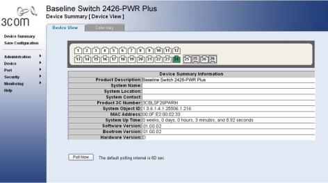
Figure 2-2 Switch Screen Layout
Table 2-3 Available Menu Items
|
Menu Item |
|
Description |
|
|
|
|
Contains tabs that allow you to: |
|
|
Device Summary |
z |
Provide a summary of the switch’s basic settings and |
|
|
|
versions of current components. |
||
|
|
|
|
|
|
|
|
z Display the description for each color coded port. |
|
|
Save Configuration |
Saves the switch’s configuration |
||
|
|
|
|
|
|
|
IP Setup |
Allows you to setup, modify, or view the IP configuration |
|
|
|
parameters. |
||
|
|
|
||
|
|
|
|
|
|
|
ARP Setting |
Allows a host to communicate with other hosts when only the |
|
|
|
IP address of its neighbors is known. |
||
|
|
|
||
|
|
|
|
|
|
|
Backup & Restore |
Allows you to backup and restore the switch’s configuration. |
|
|
|
|
|
|
|
|
Firmware |
Allows you to upgrade the current firmware via HTTP |
|
|
|
Upgrade |
||
|
|
|
|
|
|
|
|
|
|
|
|
Reset |
Allows you to reset the switch to factory default settings |
|
|
|
|
|
|
|
|
|
Contains tabs that allow you to: |
|
|
Administration |
System Access |
z Display user summary information. |
|
|
|
z Create a new user. |
||
|
|
|
z |
Modify existing users. |
|
|
|
z |
Remove existing users. |
|
|
System Name |
Allows you to set the system name. |
|
|
|
|
|
|
|
|
System Time |
Allows you to set the system time. |
|
|
|
|
|
|
|
|
Logging |
System Logs record and manage events and report errors |
|
|
|
and informational messages |
||
|
|
|
||
|
|
|
|
|
|
|
|
Contains tabs that allow you to: |
|
|
|
SNMP |
z |
Add community strings. |
|
|
|
z |
Remove community strings. |
2-3

Menu Item |
Description |
|
|
Contains tabs that allow you to:
|
|
z |
Create a VLAN. |
|
|
|
z |
Modify a VLAN. |
|
|
VLAN |
z Modify VLAN membership for a port. |
||
|
z |
Rename a VLAN. |
||
|
|
|||
|
|
z |
Remove a VLAN. |
|
|
|
z Display VLAN membership for a port. |
||
|
|
z |
Display VLAN information. |
|
|
|
Allows you to configure a Spanning Tree Protocol. |
||
|
Spanning Tree |
Contains tabs that allow you to: |
||
|
z Display selected spanning tree information for every port. |
|||
|
|
z Display individual port spanning tree information. |
||
|
|
z Modify the spanning tree settings for a port. |
||
|
|
|
||
|
IGMP Snooping |
Allows you to enable or disable IGMP snooping and IGMP |
||
|
query modes. |
|||
|
|
|||
|
|
|
||
|
Broadcast Storm |
Allows you to enable or disable broadcast control. |
||
|
|
|
||
|
ACL |
Configures the ACL. |
||
|
|
|
||
|
MAC Based ACL |
Configures MAC Based ACL on the switch. |
||
|
|
|
||
Device |
IP Based ACL |
Configures IP Based ACL on the switch. |
||
|
|
|
||
ACL Binding |
Configures ACL Binding on the switch. |
|||
|
||||
|
|
|
||
|
QoS |
Configures QoS settings. |
||
|
|
|
||
|
|
Contains tabs that allow you to: |
||
|
CoS |
z Displays CoS default settings assigned to ports. |
||
|
|
z |
Defines CoS |
|
|
Queue |
Configures Queue Setting. |
||
|
|
|
||
|
CoS to Queue |
Displays and defines CoS to Queue. |
||
|
|
|
||
|
DSCP to Queue |
Contains fields for mapping DSCP settings to traffic queues. |
||
|
|
|
||
|
Trust |
Configures Trust Settings. |
||
|
|
|
||
|
Bandwidth |
Displays and defines Bandwidth Settings. |
||
|
|
|
||
|
|
Contains tabs that allow you to: |
||
|
|
z Display Voice VLAN summary. |
||
|
VoIP Traffic |
z Configure Voice VLAN global settings. |
||
|
z Configure Voice VLAN port settings. |
|||
|
Setting |
|||
|
z Display port information for Voice VLAN. |
|||
|
|
|||
|
|
z |
Display OUI summary. |
|
|
|
z Add or remove OUI. |
||
|
LLDP |
Allows you to configure LLDP global and port settings. |
||
|
|
|
|
|
2-4
|
|
Menu Item |
|
|
Description |
|
|
|
|
|
|
Contains tabs that allow you to: |
|
|
|
|
Administration |
|
z Display selected port information for the entire switch. |
|
|
|
|
|
z Display individual port information. |
||
|
|
|
|
|
||
|
|
|
|
|
z Modify the port settings. |
|
|
|
|
|
|
Contains tabs that allow you to: |
|
|
|
|
Link Aggregation |
|
z Display link aggregation summary. |
|
|
|
Port |
|
z Create an aggregation group. |
||
|
|
|
|
z Modify the port memberships. |
||
|
|
|
|
|
z Remove an aggregation group. |
|
|
|
|
LACP |
|
Configures the LACP. |
|
|
|
|
|
|
||
|
|
|
Statistics |
Display statistics for a selected port. |
||
|
|
|
|
|
|
|
|
|
|
PoE(Only |
|
Contains tabs that allow you to: |
|
|
|
|
supported by |
|
z |
Display PoE summary. |
|
|
|
2426-PWR Plus) |
|
z |
Configure PoE settings. |
|
|
|
|
|
||
|
|
|
|
|
Contains tabs that allow you to: |
|
|
|
|
Radius Client |
|
z Display Radius Client information. |
|
|
|
|
|
z Configure Radius Client settings and set authentication |
||
|
|
|
|
|
||
|
|
Security |
|
|
|
parameters. |
|
|
|
|
Contains tabs that allow you to: |
||
|
|
|
|
|
||
|
|
|
802.1X |
|
z Display system authentication summary. |
|
|
|
|
|
z Display detailed information per port. |
||
|
|
|
|
|
||
|
|
|
|
|
z Configure system authentication settings. |
|
|
|
|
|
|
||
|
|
|
Address Table |
Displays MAC address table information for ports and VLANs. |
||
|
|
|
|
|
||
|
|
|
Port Mirroring |
Monitor traffic going in or out of ports. |
||
|
|
Monitoring |
|
|
|
|
|
|
|
|
Contains tabs that allow you to: |
||
|
|
|
Cable |
|
z |
Display selected cable diagnostics information for all |
|
|
|
Diagnostics |
|
|
ports. |
|
|
|
|
|
z Display all cable diagnostics information for a single port. |
|
|
|
Help |
|
Displays 3Com contact information and describes how to use |
||
|
|
|
the online help system. |
|||
|
|
|
|
|
||
|
|
|
|
|
||
|
|
Logout |
|
Allows you to securely log off the Web interface. |
||
|
|
|
|
|
|
|
Buttons
Depending on the screen that is currently displayed, the following buttons may appear:
zApply: Click to apply any changes that you have made.
zCancel: Click to discard any unsaved changes.
zSelect All: Allows the user to select all ports.
zSelect None: Removes the ports selected.
zHelp: Click to display the context-sensitive help information for the screen that is currently displayed. The help pages provide information on the tasks that you can perform on each screen.
2-5
3 Configuring the Switch
Configuring System Access
Network administrators can define user name, password, and access level for users using the System Access Interface. The Multi-Session Web feature is enabled on switch and allows 10 users to be created and access the switch concurrently. Access levels provide read or read/write permissions to users for configuring the switch. Login information is managed in the local database. A unique password is required of each user. Two access levels exist on the Web Interface:
zManagement access level: Provides the user with read/write access rights. There is always one management level user configured for the switch.
zMonitor access level: Provides the user with read-only system access rights.
This section contains the following topics:
z
z
z
z
Defining System Access
Modifying System Access
Removing System Access
Viewing System Access Settings
To ensure that unauthorized users do not access the Web interface, 3Com recommends that you set an admin password when you first configure the switch.
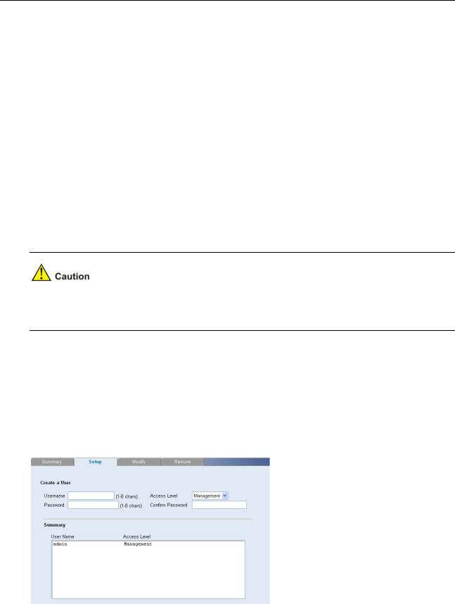
Defining System Access
The System Access Setup Page allows network administrators to define users, passwords, and access levels for users using the System Access Interface.
Click Administration > System Access > Setup. The System Access Setup Page opens.
Figure 3-1 System Access Setup Page
3-1
The System Access Setup Page contains the following fields:
Table 3-1 System Access Setup Page item description
Item |
Description |
User Name |
Defines the user name. The default value is admin. |
|
|
|
Defines the user access level. The lowest user access level is Monitor and |
|
the highest is Management. |
Access Level |
z Management: Provides the user with read and write access rights. This |
|
is the default. |
|
z Monitor: Provides the user with read access rights. |
|
|
Password |
Defines the local user password. The default is blank. |
|
|
Confirm Password |
Verifies the password. |
|
|
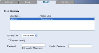
Modifying System Access
The System Access Modify Page allows network administrators to modify users, passwords, and access levels for users using the System Access Interface.
Click Administration > System Access > Modify. The System Access Modify Page opens.
Figure 3-2 System Access Modify Page
The System Access Modify Page contains the following fields:
Table 3-2 System Access Modify Page item description
Item |
Description |
|
|
Defines the user access level. The lowest user access level is Monitor and |
|
Access Level |
the highest is Management. |
|
z Management: Provides the user with read and write access rights. |
||
|
||
|
z Monitor: Provides the user with read access rights. |
|
Password Modify |
Enables modifying a password for an existing user. |
|
|
|
|
Password |
Modifies the local user password. |
|
|
|
|
Confirm Password |
Verifies the password. |
|
|
|
3-2
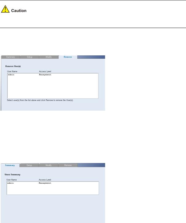
Removing System Access
The System Access Remove Page allows network administrators to remove users from the System Access Interface.
The last user with management access may not be deleted.
Click Administration > System Access > Remove. The System Access Remove Page opens.
Figure 3-3 System Access Remove Page
Viewing System Access Settings
The System Access Summary Page displays the current users and access levels defined on the switch. Click Administration > System Access > Summary. The System Access Summary Page opens.
Figure 3-4 System Access Summary Page
The System Access Summary Page contains the following fields:
3-3
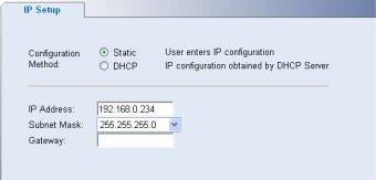
Table 3-3 System Access Summary Page item description
Item |
Description |
User Name |
Displays the user name. |
|
|
Access Level |
Displays the user access level. |
|
|
Configuring IP and MAC Address Information
This section contains information for defining IP interfaces, and includes the following sections:
z
z
z
Defining IP Address
Configuring ARP Settings
Configuring MAC Address Table
Defining IP Address
To enable the other devices on the network to communicate with the switch, you need to assign an IP address to it: either by DHCP or by assigning a static IP address.
Click Administration > IP Setup. The IP Setup Page opens.
Figure 3-5 IP Setup Page
The IP Setup Page contains the following fields:
Table 3-4 IP Setup Page item description
|
Item |
Description |
|
|
Defines whether the IP address is configured statically or dynamically. The |
|
|
possible field values are: |
|
Configuration Method |
z Static: Specifies that the IP address is configured by the user. |
|
|
z DHCP: Specifies that the IP address is dynamically obtained by DHCP |
|
|
Server. |
|
IP Address |
Defines the IP address. The default value is 169.254.xxx.xxx. If the MAC |
|
address is 08004E000102, the IP address would be 169.254.1.2. |
|
|
|
|
|
|
|
|
Subnet Mask |
Defines the subnet mask. The default value is 255.255.0.0. |
|
|
|
|
Gateway |
Defines the gateway address. The default value is blank. |
|
|
|
3-4
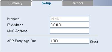
Configuring ARP Settings
The Address Resolution Protocol (ARP) converts IP addresses into physical addresses, and maps the IP address to a MAC address. ARP allows a host to communicate with other hosts when only the IP addresses of its neighbors are known.
This section includes the following topics:
z
z
z
Defining ARP Settings
Removing ARP Entries
Viewing ARP Settings
Defining ARP Settings
The ARP Settings Setup Page allows network managers to define ARP parameters for specific interfaces.
Click Administration > ARP Settings > Setup. The ARP Settings Setup Page opens.
Figure 3-6 ARP Settings Setup Page
The ARP Settings Setup Page contains the following fields:
Table 3-5 ARP Settings Setup Page item description
Item |
Description |
|
Interface |
Indicates the management VLAN (VLAN 1) for which ARP parameters are |
|
defined. |
||
|
||
|
|
|
IP Address |
Defines the static IP address, which is associated with the static MAC |
|
address. |
||
|
||
|
|
|
MAC Address |
Defines the static MAC address, which is associated with the static IP |
|
address. |
||
|
||
|
|
|
|
Specifies the aging time for dynamic ARP entries. After the ARP Entry |
|
ARP Entry Age Out |
Age, dynamic ARP entries are deleted from the table. The range is |
|
|
1-40000000. The default value is 1200 seconds. |
|
|
|
Removing ARP Entries
The ARP Entries Remove Page provides parameters for removing ARP entries from the ARP Table.
Click Administration > ARP Settings > Remove. The ARP Entries Remove Page opens.
3-5
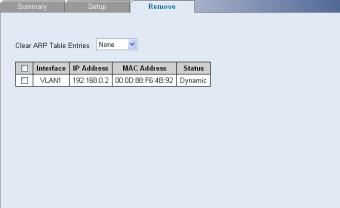
Figure 3-7 ARP Entries Remove Page
The ARP Entries Remove Page contains the following fields:
Table 3-6 ARP Entries Remove Page item description
|
Item |
|
Description |
|
|
|
Specifies the types of ARP entries that are cleared. The possible values |
|
|
|
are: |
|
Clear ARP Table |
|
z None: Maintains the ARP entries. |
|
Entries |
|
z All: Clears all ARP entries. |
|
|
|
z Dynamic: Clears only dynamic ARP entries. |
|
|
|
z Static: Clears only static ARP entries. |
|
|
|
|
|
Interface |
|
Indicates the VLAN for which ARP parameters are defined. |
|
|
|
|
|
IP Address |
|
Indicates the IP address which is associated with the MAC address. |
|
|
|
|
|
MAC Address |
|
Displays the MAC address, which is associated in the ARP table with the |
|
|
IP address. |
|
|
|
|
|
|
|
|
|
|
|
|
Displays the ARP table entry type. Possible field values are: |
|
Status |
|
z Dynamic: Indicates the ARP entry is learned dynamically. |
|
|
|
z Static: Indicates the ARP entry is a static entry. |
|
|
|
|
Viewing ARP Settings
The ARP Settings Summary Page displays the current ARP settings.
Click Administration > ARP Settings > Summary. The ARP Settings Summary Page opens.
3-6
Loading...