


 Loading...
EtherLink® Server
10/100 PCI NIC Family
User Guide
3C980x-TXM 10/100 PCI server network interface card with DynamicAccess® technology
3C982-TXM 10/100 PCI dual port server network interface card with DynamicAccess® technology
http://www.3com.com/
http://www.3com.com/productreg
Published October 2000
3Com Corporation ■ 5400 |
Copyright © 2000 3Com Corporation. All rights reserved. No part of this documentation may be |
|
Bayfront Plaza ■ Santa |
reproduced in any form or by any means or used to make any derivative work (such as translation, |
|
Clara, California ■ |
transformation, or adaptation) without written permission from 3Com Corporation. |
|
95052-8145 |
3Com Corporation reserves the right to revise this documentation and to make changes in content from |
|
|
||
|
time to time without obligation on the part of 3Com Corporation to provide notification of such revision or |
|
|
change. |
|
|
3Com Corporation provides this documentation without warranty, term, or condition of any kind, either |
|
|
implied or expressed, including, but not limited to, the implied warranties, terms or conditions |
|
|
of merchantability, satisfactory quality, and fitness for a particular purpose. 3Com may make improvements |
|
|
or changes in the product(s) and/or the program(s) described in this documentation at any time. |
|
|
If there is any software on removable media described in this documentation, it is furnished under a license |
|
|
agreement included with the product as a separate document, in the hard copy documentation, or on the |
|
|
removable media in a directory file named LICENSE.TXT or !LICENSE.TXT. If you are unable to locate a copy, |
|
|
please contact 3Com and a copy will be provided to you. |
|
|
UNITED STATES GOVERNMENT LEGEND |
|
|
If you are a United States government agency, then this documentation and the software described herein |
|
|
are provided to you subject to the following: |
|
|
All technical data and computer software are commercial in nature and developed solely at private expense. |
|
|
Software is delivered as “Commercial Computer Software” as defined in DFARS 252.227-7014 (June 1995) |
|
|
or as a “commercial item” as defined in FAR 2.101(a) and as such is provided with only such rights as are |
|
|
provided in 3Com’s standard commercial license for the Software. Technical data is provided with limited |
|
|
rights only as provided in DFAR 252.227-7015 (Nov 1995) or FAR 52.227-14 (June 1987), whichever is |
|
|
applicable. You agree not to remove or deface any portion of any legend provided on any licensed program |
|
|
or documentation contained in, or delivered to you in conjunction with, this User Guide. |
|
|
Unless otherwise indicated, 3Com registered trademarks are registered in the United States and may or may |
|
|
not be registered in other countries. |
|
|
3Com, the 3Com logo, DynamicAccess, EtherDisk, EtherLink, and Parallel Tasking are registered trademarks |
|
|
of 3Com Corporation or its subsidiaries. 3Com Facts is a service mark of 3Com Corporation or its |
|
|
subsidiaries. |
|
|
Intel and Pentium are registered trademarks of Intel Corporation. Microsoft, Windows and Windows NT are |
|
|
registered trademarks of Microsoft Corporation. NetWare and Novell are registered trademarks of Novell, |
|
|
Inc. SCO, SCO OpenServer, and UnixWare are trademarks or registered trademarks of The Santa Cruz |
|
|
Operation, Inc. |
|
|
All other company and product names may be trademarks of the respective companies with which they are |
|
|
associated. |
|
|
About This Guide |
|
|
This guide describes how to install, configure, and troubleshoot the following 3Com® network interface |
|
|
card (NIC): |
|
|
Description |
Model Number |
|
3Com EtherLink Server 10/100 PCI NIC |
3C980-TXM |
|
|
3C980B-TXM |
|
|
3C980C-TXM |
|
3Com EtherLink 10/100 PCI Dual Port Server |
3C982-TXM |
|
NIC |
|
This guide is intended for the network administrator, network operator, or network hardware installer.
Knowledge of Ethernet and the server network operating system is required.
Documentation is available in Adobe Acrobat Reader Portable Document Format (PDF) or HTML on the 3Com Web site: http://www.3com.com. You can download Acrobat Reader from the Adobe Systems Incorporated web site: http://www.adobe.com/.

CONTENTS
1 INTRODUCTION
|
Overview |
1 |
|
|
|
|
|
Advanced Server Features |
2 |
|
|
||
|
Bidirectional Load Balancing 2 |
|
|
|||
|
Self-Healing Drivers |
3 |
|
|
||
|
Failover |
3 |
|
|
|
|
|
VLANs |
4 |
|
|
|
|
|
Server Features Using Other NICs |
5 |
|
|||
|
Hot Plug NIC Installation |
5 |
|
|
||
|
Remote Wake-Up (Single Port Models Only) |
5 |
||||
|
Managed PC Boot Agent (MBA) Software |
5 |
||||
|
Desktop Management Interface (DMI) 2.0 |
6 |
||||
|
Remote System Alerts 6 |
|
|
|||
|
|
|||||
2 INSTALLING AND CONNECTING THE NIC |
||||||
|
Safety Precautions |
7 |
|
|
|
|
|
Installation Requirements |
7 |
|
|
||
|
Preparing the NIC and the Computer |
8 |
|
|||
|
Installing and Connecting the NIC |
9 |
|
|||
|
Installing Software |
11 |
|
|
|
|
|
Obtaining Installation Diskettes |
12 |
|
|||
|
Creating Diskettes in Windows |
12 |
|
|||
3 INSTALLING AND CONFIGURING IN WINDOWS
Software Installation Requirements |
13 |
|||
Getting Help 13 |
|
|
|
|
Installing in Windows NT |
13 |
|
|
|
Installing in Windows 2000 |
14 |
|
|
|
Configuring SHD Parameter Settings |
14 |
|||
Windows NT |
14 |
|
|
|
Windows 2000 |
15 |
|
|
|
Verifying Successful Installation |
16 |
|
||
Windows NT |
16 |
|
|
|
Windows 2000 |
16 |
|
|
|
Updating Software in Windows |
16 |
|
||
Windows NT |
16 |
|
|
|
Windows 2000 |
17 |
|
|
|
|
DynamicAccess Server Features |
17 |
|
|
|
|
||||
|
Planning Groups and VLANs |
17 |
|
|
|
|
||||
|
Installing DynamicAccess Software 19 |
|
|
|||||||
|
Configuring Server Features |
19 |
|
|
|
|
||||
|
Windows NT |
19 |
|
|
|
|
|
|
||
|
Windows 2000 |
19 |
|
|
|
|
|
|
||
|
Creating a Group |
|
20 |
|
|
|
|
|
|
|
|
Adding NICs to a Group |
21 |
|
|
|
|
||||
|
Specifying a Dedicated IP Address |
21 |
|
|
||||||
|
Changing an IP Address |
22 |
|
|
|
|
||||
|
Creating a VLAN |
|
22 |
|
|
|
|
|
|
|
|
Specifying Traffic Priorities (Windows NT 4.0 Only) |
23 |
||||||||
|
Saving the Configuration |
23 |
|
|
|
|
||||
|
Disabling Load Balancing for a Group |
23 |
|
|
||||||
|
Changing the Primary NIC |
24 |
|
|
|
|
||||
|
Removing a NIC from a Group 24 |
|
|
|
||||||
|
Deleting or Editing a VLAN |
24 |
|
|
|
|
||||
|
Displaying NIC Properties |
24 |
|
|
|
|
||||
|
Displaying Group Properties |
24 |
|
|
|
|
||||
|
Specifying Failover from Gigabit to 10/100 PCI |
24 |
||||||||
|
Troubleshooting a Load Balancing Configuration |
25 |
||||||||
|
Changing Windows 2000 Property Settings |
25 |
|
|||||||
|
Identifying Windows 2000 Miniport and LAN Connections 25 |
|||||||||
|
|
|
||||||||
4 INSTALLING AND CONFIGURING IN NETWARE |
|
|||||||||
|
Software Installation Requirements |
27 |
|
|
|
|||||
|
Netware Packet Receive Buffers |
27 |
|
|
|
|||||
|
Slot Numbers for Multiple NICs |
27 |
|
|
|
|||||
|
Obtaining Slot Numbers |
27 |
|
|
|
|
||||
|
Installation and Configuration Instructions |
28 |
|
|
||||||
|
Load the 3Com EtherLink Server CD |
28 |
|
|
||||||
|
Copy the Driver |
28 |
|
|
|
|
|
|
||
|
Specify the Slot Number |
29 |
|
|
|
|
||||
|
Load the Driver |
29 |
|
|
|
|
|
|
||
|
Set Up Another NIC |
29 |
|
|
|
|
|
|||
|
Install Server Features |
30 |
|
|
|
|
|
|||
|
Configure Groups |
|
30 |
|
|
|
|
|
|
|
|
Verify the Installation and Configuration 31 |
|
|
|||||||
|
Changing NetWare Driver Configuration Parameters |
32 |
||||||||
|
Configuring Groups |
34 |
|
|
|
|
|
|
||
|
Planning the Configuration |
34 |
|
|
|
|
||||
|
Adding a Secondary NIC to a Group |
35 |
|
|
||||||
|
Adding a Group |
36 |
|
|
|
|
|
|
||
|
Server Feature Commands |
37 |
|
|
|
|
||||
|
group |
38 |
|
|
|
|
|
|
|
|
|
display status |
|
38 |
|
|
|
|
|
|
|
|
help |
38 |
|
|
|
|
|
|
|
|
|
link timeout |
39 |
|
|
|
|
|
||
|
probe interval |
39 |
|
|
|
|
|
||
|
receive timeout |
39 |
|
|
|
|
|
||
|
retry count |
39 |
|
|
|
|
|
||
|
send timeout |
40 |
|
|
|
|
|
||
|
ungroup |
40 |
|
|
|
|
|
|
|
|
wait timeout |
40 |
|
|
|
|
|
||
|
Troubleshooting a Group Configuration |
41 |
|
||||||
|
|
|
|
|
|
|
|||
5 CONFIGURING THE NIC |
|
|
|
|
|
||||
|
Configuration Settings |
43 |
|
|
|
|
|
||
|
Configuration Methods 44 |
|
|
|
|
||||
|
Configuring the NIC in Windows |
44 |
|
|
|
||||
|
Configuring the Managed PC Boot Agent (MBA) 45 |
||||||||
|
Booting From the Network |
45 |
|
|
|
|
|||
|
Disabling the 3Com Logo |
46 |
|
|
|
|
|||
|
|
|
|
|
|
||||
6 TROUBLESHOOTING THE NIC |
|
|
|
|
|||||
|
Interpreting the LEDs |
47 |
|
|
|
|
|
||
|
Viewing the NIC LEDs in the Diagnostics Program |
48 |
|||||||
|
Accessing the 3Com Knowledgebase |
48 |
|
|
|||||
|
Accessing the 3Com NIC Help System |
48 |
|
|
|||||
|
Accessing Other Information |
48 |
|
|
|
|
|||
|
Troubleshooting the Network Connection |
49 |
|
||||||
|
Troubleshooting Remote Wake-Up |
49 |
|
|
|||||
|
Removing the Network Driver 50 |
|
|
|
|||||
|
Windows NT |
50 |
|
|
|
|
|
|
|
|
Windows 2000 |
51 |
|
|
|
|
|
||
|
NetWare |
51 |
|
|
|
|
|
|
|
|
Removing Server Features |
51 |
|
|
|
|
|||
|
Windows NT and Windows 2000 |
51 |
|
|
|||||
|
NetWare |
52 |
|
|
|
|
|
|
|
|
Removing 3Com NIC Diagnostics |
52 |
|
|
|
||||
|
Windows NT and Windows 2000 |
52 |
|
|
|||||
|
|
|
|||||||
7 RUNNING NIC DIAGNOSTICS IN WINDOWS |
|
||||||||
|
Overview 53 |
|
|
|
|
|
|
|
|
|
Running the NIC Test |
53 |
|
|
|
|
|
||
|
Running the Network Test |
54 |
|
|
|
|
|||
|
Viewing Network Statistics |
54 |
|
|
|
|
|||
|
Using the 3Com Icon in the Windows System Tray |
54 |
|||||||
|
Enabling the Icon |
54 |
|
|
|
|
|
||
|
Displaying Network Statistics |
55 |
|
|
|
||||

A |
INSTALLING A 3COM NIC WHILE INSTALLING THE NOS |
|||
|
Windows Fresh Installation |
57 |
||
|
Windows NT |
57 |
|
|
|
Windows 2000 |
57 |
|
|
|
NetWare Fresh Installation |
57 |
||
|
Requirements |
57 |
|
|
|
Installation Instructions |
57 |
||
B |
|
|||
INSTALLING THE 3COM DMI AGENT |
||||
|
Overview 59 |
|
|
|
|
System Requirements |
60 |
|
|
|
Installation Instructions |
60 |
||
C |
|
|
|
|
SPECIFICATIONS |
|
|
|
|
D |
|
|
||
TECHNICAL SUPPORT |
|
|||
|
Online Technical Services |
63 |
||
|
World Wide Web Site |
63 |
||
|
3Com FTP Site |
63 |
|
|
Support from Your Network Supplier 63
Support from 3Com 64
Returning Products for Repair 66
INDEX
3COM CORPORATION LIMITED WARRANTY
REGULATORY INFORMATION
3COM END USER SOFTWARE LICENSE AGREEMENT
PRODUCT REGISTRATION
INTRODUCTION
1
Overview |
The 3Com® EtherLink® Server 10/100 PCI NIC family of network interface cards (NIC) |
|
connect PCI-compliant server computers to Ethernet or Fast Ethernet networks. |
|
Parallel Tasking II® hardware technology, plus a powerful suite of DynamicAccess® |
|
technology software features, relieve network congestion and ensure high |
|
performance and maximum bandwidth availability. |
|
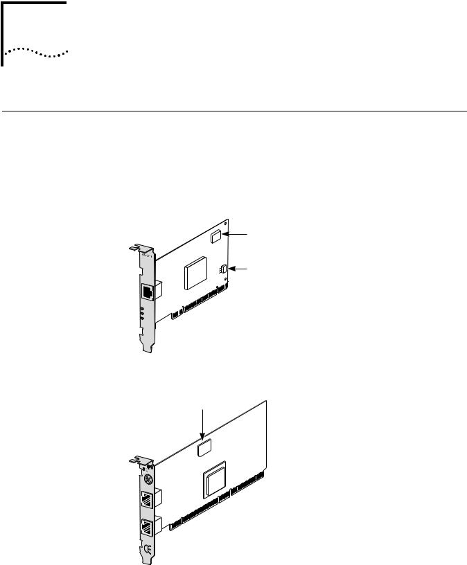
Figure 1 EtherLink Server 10/100 PCI NIC |
|
MBA Boot ROM |
|
Remote Wake-Up |
|
(RWU) connector |
TX |
|
DATA |
|
ACT |
|
10 |
L |
100N K
Figure 2 Dual Port EtherLink Server 10/100 PCI NIC
MBA
Boot ROM
 ACT
ACT
A
 10/100
  ACT
ACT
 10/100
B

2 CHAPTER 1: INTRODUCTION
Each NIC supports these features:
■ Advanced Server Features—Improve network performance, management, and control.
■ Hot Plug NIC Installation—Lets you add a new NIC or remove and replace a NIC without turning off power to the computer.
■ Remote Wake-Up (Single Port Models Only)—Lets you power-on a computer remotely for after-hours administration.
■ Integrated boot ROM (through port A on 3C982-TXM) with Managed PC Boot Agent (MBA) Software—Adds management capabilities by enabling the computer to boot from another computer, rather than from its local drive.
|
■ Desktop Management Interface (DMI) 2.0—Enables managed computers and |
|
net computers to report details about themselves and their peripheral devices |
|
across the network to a DMI 2.0-compliant management application. |
|
■ Remote System Alerts (heartbeat packets)—Can signal a possible computer |
|
power loss or theft. |
|
|
Advanced Server |
3Com DynamicAccess technology advanced network software adds intelligence to |
Features |
the NIC to improve network performance, management, and control. |
|
DynamicAccess server features relieve network congestion and ensure high |
|
performance and maximum bandwidth availability. |
|
■ Self-healing drivers (SHDs) detect common error conditions and correct them |
|
while maintaining server link performance. |
|
■ Bidirectional load balancing groups share the network load over resilient server |
|
links (RSLs) that keep traffic flowing both into a server and out of a server even |
|
if a NIC in a group is temporarily disconnected. |
|
■ VLANs (IEEE 802.1Q multiple virtual LANs) let you divide network segments |
|
into logical partitions that simplify configuration changes, organize work |
|
groups efficiently, help to control traffic, and provide extra security. |
|
■ Traffic prioritization (IEEE 802.1p/Q)—Ensures that business-critical and |
|
delay-sensitive traffic (such as multimedia applications) has priority over normal |
|
data. |
|
For detailed information on DynamicAccess technology products, go to: |
|
http://www.3com.com/dynamicaccess |
Bidirectional |
Bidirectional load balancing maximizes bandwidth at the server through the use of |
Load Balancing |
multiple parallel resilient server links (RSLs) that share the network load. |
|
An RSL consists of two or more NICs that form a virtual NIC. Each virtual NIC has |
|
multiple physical NICs bound to it, forming a group. Each NIC in a group uses the |
|
same protocols and frame types. One NIC is designated the primary NIC and the |
|
others secondary NICs. |

Advanced Server Features |
3 |
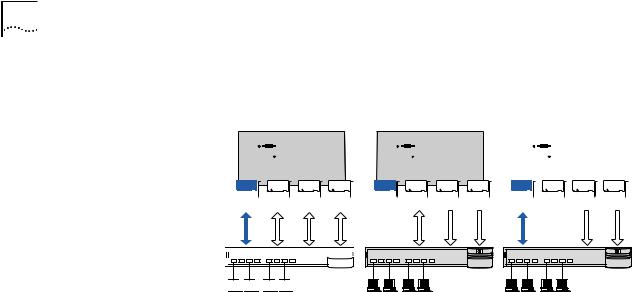
Figure 3 Types of Load Balancing Arrangements
Transmit-only |
Bidirectional |
Server
Primary Secondaries |
Primary Secondaries |
Switch 
Clients
Self-Healing Drivers Self-healing drivers (SHDs) work together with RSLs to maintain the network connection. An SHD monitors the NIC continuously for error conditions and makes corrections. These corrections can include resetting the NIC, rebuilding software data structures, temporarily disabling features, or transferring all network traffic to secondary NICs (termed a failover event). An SHD can also continuously monitor the status of the physical NICs in a virtual NIC group before and after failover. Errors and actions are reported to the system console and to the system log file. Error threshold values can be configured at any time.
Failover In addition to load balancing, RSLs provide failover fault tolerance between a server and a switch—if one NIC in a group fails, the others assume the network load of the failed NIC. The failover behavior of secondary NICs depends on how you set load balancing:
■In a transmit load balancing arrangement, the primary NIC is the only one that receives packets. If the primary NIC fails, a secondary NIC assumes the configuration profile, network traffic, and active status of the failed
primary NIC.
■In a bidirectional load balancing arrangement, all NICs receive packets. If any NIC fails, receive load balancing is disabled, and the other NICs continue transmit-only load balancing activity. Receive load balancing is restored when new connections are established with clients.
Bidirectional load balancing is restored after a failure when applications create new connections and new clients log in.
4 CHAPTER 1: INTRODUCTION
Figure 4 Bidirectional Load Balancing Failover
|
|
Bidirectional |
|
|
|
|
|
|
|
|
||
|
load balancing |
|
Primary failure |
Secondary failure |
||||||||
Server |
|
|
|
|
|
|
|
|
|
|||
|
|
|
|
|
|
|
|
|
||||
|
|
|
|
|
|
|
|
|
|
|
|
|
|
|
|
|
|
|
|
|
|
|
|
|
|
|
|
|
|
|
|
|
|
|
|
|
|
|
|
|
|
|
|
|
|
|
|
|
|
|
|
Primary Secondaries |
Primary Secondaries |
Primary Secondaries |
Switch 
Clients 


VLANs A VLAN is a group of location-independent and topology-independent devices that communicate as if they were on the same physical LAN. Network devices on different LAN segments and of different media types can be members of the same VLAN. Membership in a VLAN is determined by a VLAN tag that is transmitted with the Ethernet frame for use by a switch.
With VLANs, you can define a network according to:
■Organizational groups—For example, you can have one VLAN for the Marketing department and one for the Finance department.
■Application groups—For example, you can have one VLAN for e-mail users and one for multimedia users.
Implementing VLANs on a network has these advantages:
■It eases the change and movement of devices on IP networks.
With traditional IP networks, if users move to a different IP subnet, the IP addresses of each workstation must be updated manually. With VLANs installed, if an end station on VLAN 1 is moved to a port elsewhere on the network, you need only to specify that the new port is on VLAN 1.
■It helps to control traffic.
With traditional networks, congestion can be caused by broadcast traffic that is directed to all network devices whether they require it or not. Each VLAN can be set up to contain only those devices that need to communicate with each other, increasing network efficiency.
■It provides extra security.
Devices within each VLAN can communicate only with member devices in the same VLAN. If a device in VLAN 1 needs to communicate with devices in VLAN 2, the traffic must cross a router.
The DynamicAccess technology multiple VLAN capability supports IEEE 802.1Q VLAN tagging and works with any switch that is compliant with IEEE 802.1Q specifications. See your Ethernet switch documentation for more information on IEEE 802.1Q VLANs.
|
Hot Plug NIC Installation 5 |
Server Features Using |
Two foreign NICs (two that are not 3Com EtherLink Server NICs) are allowed per |
Other NICs |
server. For guidelines on using foreign NICs, see these topics: |
|
■ Windows NT and Windows 2000—Planning Groups and VLANs on page 17. |
|
■ NetWare—Planning the Configuration on page 34. |
|
|
Hot Plug NIC |
If your computer supports PCI hot plug specifications, you can add a new 3Com |
Installation |
NIC or remove and replace a 3Com NIC without turning off power to the |
|
computer. Hot plug NIC installation allows you to expand connections without |
|
taking the computer out of service and makes troubleshooting faster and easier |
|
because you do not need to wait for the computer to reboot. |
|
For instructions on performing a hot plug NIC installation, refer to your computer |
|
documentation and to the HOTPLUG.TXT file in the HELP directory on the 3Com |
|
EtherLink Server CD. |
|
|
Remote Wake-Up |
Remote Wake-Up is the ability to remotely power-on a computer for after-hours |
(Single Port Models |
administration. |
Only) |
If the computer is compliant with PCI 2.2, Remote Wake-Up is automatically |
|
|
|
enabled through the PCI bus. If the computer is compliant with PCI 2.1, Remote |
|
Wake-Up support is enabled by connecting a Remote Wake-Up cable from the NIC |
|
Remote Wake-Up (RWU) connector to a 3-pin Remote Wake-Up connector on the |
|
computer motherboard. |
|
The following items are needed to use Remote Wake-Up: |
|
■ Management application that supports Remote Wake-Up |
|
■ BIOS that supports Remote Wake-Up |
|
■ PCI 2.2-compliant bus or a 3-pin Remote Wake-Up connector on the computer |
|
motherboard and a 5-volt standby power supply unit rated at a minimum of |
|
375 milliamperes |
|
■ A power supply in the computer that can support multiple Remote Wake-Up |
|
devices (to use multiple NICs as Remote Wake-Up NICs in the same computer) |
|
If you are unsure whether the computer meets the requirements listed above, refer |
|
to the computer documentation or contact the computer manufacturer. |
|
For more information on Remote Wake-Up, including a list of computers that |
|
currently support this feature, go to: |
|
http://www.3com.com/partners/acpi |
|
|
Managed PC Boot |
The Managed PC Boot Agent (MBA) software adds management capabilities to |
Agent (MBA) |
the NIC, enabling the computer to boot from the server, rather than from its |
Software |
local drive. |
|
This preboot support allows you to use management applications to perform the |
|
following tasks remotely: |
|
■ Install and configure a new computer that has never been connected to the |
|
network. |

6 CHAPTER 1: INTRODUCTION
■Upgrade software.
■Configure or reconfigure multiple systems simultaneously.
■Scan for viruses.
■Back-up hard drives and perform disaster recovery tasks.
For information on configuring the MBA to boot from the network, see
Configuring the Managed PC Boot Agent (MBA) on page 45.
For detailed information on the MBA, see the Managed PC Boot Agent User
Guide, located with the MBA software on the 3Com EtherLink Server CD.
Desktop Management DMI 2.0 enables managed computers and net computers to report details about Interface (DMI) 2.0 themselves and their peripheral devices across the network to a DMI
2.0-compliant management application.
A network administrator can then use this information to configure and manage a client or server computer remotely.
For instructions on installing the 3Com DMI Agent, see Installing the 3Com DMI Agent on page 59.
For more detailed information on DMI, go to:
http://www.3com.com/managedpc
Remote System Alerts The NIC can be configured to continuously transmit a packet to an alert target management station. If the management station fails to receive the regularly scheduled packet, an alert can be triggered that signals a possible computer power loss or theft.
The NIC can also transmit a workgroup keep-alive packet periodically while the computer is in a sleep state. This packet prevents the computer workstation address from being aged-out of switch router tables.

INSTALLING AND CONNECTING THE NIC
2
Safety Precautions Observe the following safety precautions:
WARNING: Computers operate with voltages that can be lethal. Before removing the cover, turn off the computer and unplug it. Disconnect all cables that are connected to the main system unit. Remove jewelry from your hands and wrists. Use insulated or nonconductive tools.
CAUTION: The NIC is packed in an antistatic container to protect it during shipment. Do not touch the components or any metal parts on the NIC, except for the backplate. To avoid damaging the NIC or the computer, reduce static electricity on your body by wearing an electrostatic discharge wrist strap attached to the chassis or by touching an unpainted metal part of the chassis before unplugging the computer and before handling the NIC.
CAUTION: Install the NIC in a PCI slot that conforms to PCI 2.1 or higher specifications. Do not attempt to install the NIC in an ISA or EISA slot. Doing so may damage the NIC and the computer.
WARNING: Make sure that the computer power cord is unplugged. Only properly trained and authorized personnel should perform service. Contact the computer manufacturer for information about safe service techniques.
Installation
Requirements
The following items are required for hardware and software installation:
■NIC—At least one 10/100 NIC.
■Processor—Intel-based CPU (Pentium-class processor).
■Server RAM—128 megabytes minimum; 256 megabytes recommended.
■PCI slot—For each NIC, one bus master slot that conforms to PCI 32/64-bit specifications, revision 2.1 or 2.2.
■Drive—CD-ROM.
■Cable—Category 5 UTP (for 100 Mbps operation).
■Connector—RJ-45, one or two ports.
■Software—One 3Com EtherLink Server CD with DynamicAccess technology software and network drivers.

8CHAPTER 2: INSTALLING AND CONNECTING THE NIC
■Operating system—Base drivers and DynamicAccess software are available for the following operating systems:
■Microsoft Windows NT version 4.0 with the most recent Service Pack available from Microsoft technical support (www.microsoft.com).
■Microsoft Windows 2000 with the most recent Service Pack available from Microsoft technical support (www.microsoft.com).
■Novell NetWare version 4.2 or 5.x with the most recent patches and updates available from Novell technical support (www.novell.com).
Base drivers are also available for the following operating systems:
■SCO UnixWare 7 available on the 3Com Web site (http://support.3Com.com/infodeli/tools/nic/SCO.htm).
■SCO OpenServer 5 available on the 3Com Web site (http://support.3Com.com/infodeli/tools/nic/SCO.htm).
■Linux available on the 3Com Web site (http://support.3Com.com/infodeli/tools/nic/linux.htm).
Check the 3Com Web site (http://support.3Com.com/infodeli/tools/nic) for other supported drivers.
■Computer BIOS—Latest version. Contact the computer manufacturer to verify.
■Remote Wake-Up—For requirements, see Remote Wake-Up (Single Port Models Only) on page 5.
Preparing the NIC and Observe the precautions listed in Safety Precautions on page 7. Follow these the Computer preparation steps:
1Decide if you want to use the Remote Wake-Up feature.
If you want to use the Remote Wake-Up feature on a computer that is compliant with PCI 2.1, you must obtain a Remote Wake-Up cable for the NIC (for details, see Remote Wake-Up (Single Port Models Only) on page 5). If the computer is compliant with PCI 2.2, Remote Wake-Up is automatically enabled through the PCI bus and no Remote Wake-Up cable is required.
2Make sure that cable requirements are met.
The RJ-45 port provides a 10 Mbps or 100 Mbps connection automatically, depending on the speed of the connected hub or switch.
The following table shows the cable requirements and maximum network cable lengths for the RJ-45 port.
|
|
Maximum |
Network Environment |
Cable Required |
Cable Length |
|
|
|
10 Mbps (10BASE-T) |
Category 3, 4, or 5 unshielded |
100 m (328 ft) |
|
twisted-pair |
|
|
|
|
100 Mbps (100BASE-TX) |
Category 5 unshielded twisted-pair |
100 m (328 ft) |
|
|
|

Installing and Connecting the NIC |
9 |
3Unpack and inspect the NIC for damage.
4Exit all open applications and user processes.
5Turn off the power to the computer and attached devices.
6Unplug the power cables from the power source.
7Remove the computer cover.
8Locate an empty, nonshared bus-mastering PCI slot and remove its slot cover. Save the screw, if there is one.
Do not install the NIC in a shared PCI slot. Avoid any PCI slot next to an ISA slot. This is often a shared slot and does not support bus mastering.
If you do not know how to identify a PCI slot, check the computer documentation or ask the system administrator.
If you are planning to install the Remote Wake-Up cable, choose an empty PCI slot that is close to the matching connector on the computer motherboard. The Remote Wake-Up cable is required only if the computer is compliant with PCI 2.1 and you want to use the Remote Wake-Up. The cable is not required if the computer is compliant with PCI 2.2.
9Write down the MAC address of the NIC and note the relative position of the intended PCI slot.
This information is helpful when you are installing the network drivers and connecting the cables to the hub or switch. The MAC address is the 12-digit hexadecimal number printed on the small bar code label on the component side of the NIC.
The next step is to install the NIC in the computer and connect it to the network.
Installing and |
Observe the safety precautions listed in Safety Precautions on page 7. |
Connecting the NIC |
Prepare the NIC and the computer as described in Preparing the NIC and the |
|
|
|
Computer on page 8. |
|
The following instructions apply to installing the NIC in most computers. If these |
|
instructions are not appropriate for your computer, refer to the documentation |
|
that accompanied the computer. |

10 CHAPTER 2: INSTALLING AND CONNECTING THE NIC
Figure 5 Installing and Connecting the NIC
DATA |
|
ACT |
|
10 |
L |
100 |
N |
|
K |
+
–
1Carefully insert the NIC into an empty PCI slot.
Press firmly to ensure that the NIC is fully seated in the slot. Secure the NIC with the screw if you removed one earlier.
2Follow these steps only if you need to connect a Remote Wake-up cable:
■Make sure that the NIC is properly installed in a PCI slot.
■Insert the Remote Wake-Up cable in the RWU connector on the NIC. Twist the cable two times before attaching the cable to the computer.
■Attach the other end of the cable to the connector on the computer motherboard. Refer to the computer documentation if you need help locating the connector.
3Replace the computer cover and plug in the power cord.
Do not turn on the power to the computer.

Installing Software 11
4Plug the RJ-45 connector on the twisted-pair network cable into an RJ-45 port on the NIC backplate.
If you are installing a dual port NIC, plug the first cable into Port A on the NIC backplate.
5Connect the other end of the network cable to an active network port. The next step is to install the software.
If your site network installation procedures require you to verify that installed hardware is functional before you install software, run the 3C90XCFG.EXE DOS diagnostics program before installing the driver. This program is located on the 3Com EtherLink Server CD.
Figure 6 Connecting a Remote Wake-up Cable (PCI 2.1 only)
Installing Software See the following topics for requirements and instructions on installing software in various operating systems:
■Installing and Configuring in Windows on page 13
■Updating Software in Windows on page 16.
■Installing and Configuring in NetWare on page 27

12 CHAPTER 2: INSTALLING AND CONNECTING THE NIC
Obtaining Installation If your computer does not have a CD-ROM drive, access a computer that has a Diskettes CD-ROM drive and use the installation utilities to create installation diskettes from
files on the 3Com EtherLink Server CD.
If you do not have access to a computer that has a CD-ROM drive, you can download the drivers from the 3Com web site:
http://www.3com.com/
Creating Diskettes in Use the installation utilities on the 3Com EtherLink Server CD to create installation Windows diskettes. The installation diskettes allow you to install drivers, diagnostics,
DynamicAccess technology server features, and associated text files. The installation diskettes do not contain the user guide that is available on the 3Com EtherLink Server CD.
You will need five blank formatted diskettes.
To create the installation diskettes:
1Turn on the power to the computer and start Windows.
2Insert the 3Com EtherLink Server CD in the CD-ROM drive.
3On the Welcome screen, click on NIC Software.
4Click Installation Utilities.
5Click on Create Installation Diskettes.
6Follow the prompts to copy files to the diskettes.

INSTALLING AND CONFIGURING IN
3 WINDOWS
Software Installation Before you install software, you may want to verify that the installed server NICs Requirements are functional or change their configuration settings by running DOS diagnostics.
Use the 3C90XCFG.EXE program located on the 3Com EtherLink Server CD.
If you are installing the software during the installation of the network operating system, see Installing a 3Com NIC While Installing the NOS on page 57.
For a list of installation requirements, see Installation Requirements on page 7.
The installation instructions assume you are using the Windows Auto Run feature. If the Welcome screen does not come up automatically, you can perform the installation by running begin.exe.
Getting Help |
To display the Help system during the software installation, click Help on any |
|
3Com window. |
Installing in
Windows NT
Before you begin software installation:
■Make sure that all installation requirements are met. See Installation Requirements on page 7.
■Install the hardware. See Installing and Connecting the NIC on page 9.
Use the following procedure to install the driver and diagnostics for the first time in a computer that is running Windows NT. (If you are updating a previous installation, see Updating Software in Windows on page 16.)
1Boot the computer and start Windows NT.
2Log in to the Windows NT Administrator account.
3Insert the 3Com EtherLink Server CD in the CD-ROM drive.
4From the Welcome screen, select NIC Software.
5Click NIC Drivers and Diagnostics.
6Follow the Wizard prompts.
7Choose Typical or Custom Installation.
The Please Wait screen appears. After the installation is completed, an Update dialog box appears.

14 CHAPTER 3: INSTALLING AND CONFIGURING IN WINDOWS
8Click OK.
The Setup Complete screen appears.
If your network environment uses the TCP/IP communications protocol, the Microsoft TCP/IP Properties dialog box appears. Enter the information needed to define an IP address. Continue after you have defined the TCP/IP settings.
9Click Finish to complete the installation.
10Click Exit.
11Restart your computer for changes to take effect.
Installing in Windows 2000
Before you begin software installation:
■Make sure that all software installation requirements are met. See Installation Requirements on page 7.
■Install the hardware. For instructions, see Installing and Connecting the NIC on page 9.
Use the following procedure to install the driver and diagnostics for the first time in a computer that is running Windows 2000. (If you are updating a previous installation, see Updating Software in Windows on page 16.)
1Reboot the computer, start Windows 2000, and log in to the Windows 2000 Administrator account.
The Windows 2000 Found New Hardware wizard detects the new NICs and begins the driver installation.
2Insert the 3Com EtherLink Server CD in the CD-ROM drive.
3From the main menu, select NIC Software.
4From the list on the left, click NIC Drivers and Diagnostics.
5Follow the Wizard prompts.
6Choose Typical or Custom Installation.
The Please Wait screen appears. After the installation is completed, an Update dialog box appears.
7Click OK
The Setup Complete screen appears.
8Click Finish to complete the installation.
9Click Exit.
Configuring SHD |
Follow the procedure for your operating system. |
Parameter Settings |
|
Windows NT
1Right-click My Network Places and select Properties from the menu.
2In the next window, right-click a connection and select Properties from the menu.
3Click Configure.
Configuring SHD Parameter Settings 15
4In the NIC Properties window, click the Advanced tab.
5In the Advanced window, you can configure the SHD parameters. Select a parameter in the Property field and change its value in the Value field. Table 1 describes the SHD parameters. Default values are optimal for most networks.
Windows 2000
1From the Windows Start menu, select Settings/Control Panel.
2Double-click the Network icon.
3In the Network window, click the Adapters tab.
4Double-click the adapter you want to modify
5Double-click a parameter to change its value. Table 1 describes the SHD parameters. Default values are optimal for most networks.
Slot numbers listed in the SHD Configuration window may not match those labeled on the mother board
6When you are finished, click OK.
7Remove the 3Com EtherLink Server CD from the CD-ROM drive.
8Restart the computer.
Table 1 SHD Parameters (Windows)
|
Range of Values |
|
Field |
(Defaults in Bold) |
Description |
|
|
|
Self Check |
Off, Basic, Enhanced |
Basic level checking monitors Tx/Rx errors (see |
Level |
|
Sampling Window), link beat, and NIC hardware. |
|
|
Enhanced level adds maintenance of valid data |
|
|
structures and uses more CPU cycles. Basic level |
|
|
checking is forced when RSL is enabled. Off disables |
|
|
SHD. |
Sampling |
0–65536 packets |
This option specifies the number of Tx/Rx packets to |
Window |
0 disables sampling. |
be sampled for carrier lost, late collisions, jabbers, |
|
1024 |
CRC, overruns, underruns, and bus contention |
|
|
errors. Setting the Sampling Window to 0 effectively |
|
|
disables all checking. |
Sampling Ratio |
0–100 percent |
Sampling Ratio establishes a rate of error |
|
50 |
accumulation. Every second, the error counters are |
|
|
diminished by the Sampling Ratio. The larger the |
|
|
Sampling Ratio, the more recent are the |
|
|
accumulated errors. |
Error Tolerance |
Low |
Error Tolerance specifies threshold levels for Tx/Rx |
|
Medium |
errors. An RSL failover or NIC reset occurs when the |
|
High |
threshold is exceeded during the sampling period. |
|
|
Low = 5 of each error category |
|
|
Medium = 50 of each error category |
|
|
High = 100 of each error category |
Alert Type |
Information |
Double-click to enable or disable alert types. Enabled |
(Windows NT) |
Warning |
types are reported to the Windows System Events |
|
Error |
monitor. |

16 CHAPTER 3: INSTALLING AND CONFIGURING IN WINDOWS
Table 1 SHD Parameters (Windows) (continued)
|
Range of Values |
|
Field |
(Defaults in Bold) |
Description |
|
|
|
SHD Inform |
Enabled |
Select a parameter in the Property field and change |
messages |
Disabled |
its value in the Value field. Enabled types are |
SHD Warning |
|
reported to the Windows System Events monitor. |
|
|
|
messages |
|
|
SHD Error |
|
|
messages |
|
|
(Windows 2000) |
|
|
|
|
|
Verifying Successful Follow the procedure for your operating system.
Installation
Windows NT
1Double-click the My Computer icon, then the Control Panel icon, and then the Network icon.
2Select the Adapters tab.
3Make sure that the name of the NIC appears in the list of network adapters.
Windows 2000
1Right-click My Network Places and select Properties from the menu.
2Check connections in the Network and Dial-up Connections window.
Updating Software in |
The following procedures update a previous installation of the network driver and |
Windows |
NIC diagnostics software in Windows. |
Windows NT
1Boot the computer and start Windows NT.
2Log in to the Windows NT Administrator account.
3Insert the 3Com EtherLink Server CD in the CD-ROM drive.
4From the Welcome screen, select NIC Software.
5Click NIC Drivers and Diagnostics. The Please Wait screen appears.
6Follow the Wizard prompts.
7Choose Custom Installation.
8Select the desired installation option.
9Click Next.
10Choose any advanced features you would like set.
11Click Next.
12Click OK.
13Click Finish to complete the installation.

DynamicAccess Server Features |
17 |
14Click Exit.
15Restart your computer for changes to take effect.
After you restart the computer, you may wish to configure self-healing drivers. To do so, bring up the Adapters tab in the Network window, select a NIC, and click Properties. For details on the SHD parameters, see SHD Parameters (Windows) on page 15.
Windows 2000
1Reboot the computer, start Windows 2000, and log in to the Windows 2000 Administrator account.
The Windows 2000 Found New Hardware Wizard detects the new NICs and begins the driver installation.
2Insert the 3Com EtherLink Server CD in the CD-ROM drive.
3From the Welcome screen, select NIC Software.
4Click NIC Drivers and Diagnostics.
5Follow the Wizard prompts.
6Choose Custom Installation.
7Select the desired installation option.
8Click OK
The Setup Complete screen appears.
9Click Finish to complete the installation.
10Click Exit.
DynamicAccess Server
Features
Planning Groups and
VLANs
DynamicAccess technology server features allow you to configure load balancing groups and virtual LANs (VLANs). The features are described in Advanced Server Features on page 2.
The following DynamicAccess technology server features are available for NIC groups in Windows:
■Bidirectional load balancing
■RSL failover
■Multiple VLANs
The examples in this section illustrate typical actions you might take in the course of maintaining a DynamicAccess server configuration in Windows.
Consider these items when planning groups and VLANs:
■Decide whether you want to use bidirectional load balancing, or transmit load balancing.
To use bidirectional load balancing, you must assign a dedicated IP address for each load balancing group. This address must be unique (not used elsewhere on the network). For details, see Specifying a Dedicated IP Address on page 21.

18CHAPTER 3: INSTALLING AND CONFIGURING IN WINDOWS
■Decide which NICs are to be part of each group. Each group must include at least two NICs.
■Decide whether you want to use a foreign NIC in one of the groups.
Two foreign NICs (two that are not 3Com EtherLink Server NICs) are allowed in one group per server.
■Decide which NIC is to be the primary NIC in each group.
■You can specify failover from a Gigabit NIC to a 10/100 NIC. To ensure optimal performance, this type of failover requires that you disable load balancing for the group.
■For the best failover performance, turn the spanning tree feature off at switches that are connected directly to the server. If the spanning tree feature is turned on, a failover may be delayed up to 30 seconds while the switch processes the spanning tree algorithm.
■Plan the cable changes required to connect each primary NIC and all secondary NICs to the same network segment.
■Observe the recommended support limit of four groups per server.
■The following guidelines apply to groups under Windows 2000:
802.1p Support Property—The value of the Windows 2000 802.1p Support property must be the same for all NICs in a group. For example, if this property is enabled for the primary NIC, it must also be enabled for all other NICs in the group.
Microsoft Task Offload Support—It is possible to form a group of NICs that have different levels of support for Microsoft Task Offload features (TCP Checksum, TCP Segmentation, and IP Sec). In this case, the offload support is limited to the features supported by all NICs in the group. For example, if two NICs in a group support all offload features but one NIC supports only TCP Checksum, then offload support for the group is limited to TCP Checksum.
■Observe these VLAN configuration guidelines:
■Assign a VLAN ID number to each VLAN. If you are not using a DHCP server, each VLAN that is using IP services requires an IP address and subnet mask.
■DynamicAccess software supports as many as 16 VLANs per server.
■Each VLAN bound to TCP/IP must exist on a separate IP subnet. DHCP servers used to allocate IP addresses must be located on the same IP subnets as the VLANs.
■Each VLAN bound to the IPX/SPX protocol must use a unique network number.
■Under Windows 2000, when VLANs are enabled, the Windows 2000 802.1p Support property must be disabled for all the underlying miniports.
■A minimum of 128Mb of RAM is required for multiple VLAN configurations (up to a maximum of 16 VLANs). You can improve overall system performance with VLANs by increasing the physical RAM, the virtual memory page size, or both.

DynamicAccess Server Features |
19 |
Installing Use the following procedure to install DynamicAccess technology server features DynamicAccess in a computer that is running Windows NT or Windows 2000.
Software
Installing teaming software from multiple vendors may cause problems with your system. Before installing DynamicAccess software, uninstall any other teaming software you may have previously installed on your computer.
1Insert the 3Com EtherLink Server CD in the CD-ROM drive.
2From the Welcome screen, select NIC Software.
3Click DynamicAccess Technology.
4Click Install DynamicAccess Server Software.
5Select Windows 2000 or Windows NT installation.
6Click OK to Install the DynamicAccess server software.
7Restart your system.
Configuring Server
Features
When DynamicAccess server features are installed, NICs bind to the DynamicAccess protocol and real protocols bind to the DynamicAccess Miniport. Do not modify these bindings.
The DynamicAccess server features window contains tabs for these windows:
■In the Load Balance/RSL window, you can create and change Load Balancing/RSL groups. The NICs in a group work together to route traffic efficiently and to recover from failures.
■In the VLANs window, you can set up virtual LANs. All groups listed in the Load Balance/RSL window also appear as groups in the VLAN window. Any ungrouped NICs in the Load Balance/RSL window are also listed in the VLAN window.
Windows NT
Start DynamicAccess server features under Windows NT as follows:
1Log in to the Windows NT Administrator account.
2From the Windows Start menu, select Settings/Control Panel.
3Double-click the DynamicAccess Server icon.
The DynamicAccess Resilient Server Link/Load Balance/VLAN Configuration window appears. Click the appropriate tab to configure server features.
Windows 2000
Access DynamicAccess server features through the Windows 2000 Network and Dial-up Connections window as follows:
1Log in to Windows 2000 with administrator privileges.
2Launch the Windows 2000 Network and Dial-up Connections window.
3Select a Local Area Connection icon.
4Click the right mouse button and select Properties.
The Local Area Connections Properties window appears.
Loading...